Magtek EXCELLA STX Installation And Operation Manual
Hide thumbs
Also See for EXCELLA STX:
- Installation manual (2 pages) ,
- Quick installation manual (2 pages)
Table of Contents
Advertisement
Quick Links
Advertisement
Table of Contents

Related Manuals for Magtek EXCELLA STX


Summary of Contents for Magtek EXCELLA STX
- Page 1 EXCELLA STX MICR CHECK READER AND DUAL-SIDED SCANNER INSTALLATION AND OPERATION MANUAL Manual Part Number: 99875342-1 MARCH 2006 REGISTERED TO ISO 9001:2000 1710 Apollo Court Seal Beach, CA 90740 Phone: (562) 546-6400 FAX: (562) 546-6301 Technical Support: (651) 415-6800 www.magtek.com...
- Page 2 Information in this document is subject to change without notice. No part of this document m be reproduced or transmitted in any form or by any means, electro nic or mechanical, for any purpose, without the express written permission of MagTek, Inc. agTek is a registered trademark of MagTek, Inc. Excella STX is a trademark of MagTek, Inc.
- Page 3 MagTek warrants that the products sold to Reseller pursuant to this Agreement will perform in accordance with MagTek’s published specifications. This warranty shall be provided only for a period of one year from the date of the shipment of the product from MagTek (the “Warranty Period”). This warranty shall apply only to the original...
- Page 4 Agency approvals are pending: FCC WARNING STATEMENT This equipment has been tested and found to comply with the limits for a Class A digital device, pursu to Part 15 of FCC Rules. These limits are designed to provide reasonable protection against harmful interference when the equipment is operated in a commercial environment.
-
Page 5: Table Of Contents
TABLE OF CONTENTS CTION 1. FEATURES AND SPECIFICATIONS ..................1 CONFIGURATIONS ..........................1 REQUIREMENTS............................. 1 FEATURES............................... 1 ACCESSORIES ............................2 SPECIFICATIONS............................ 2 CTION 2. INSTALLATION........................5 INSTALLATION SUMMARY........................5 VER REMOVAL ..........................5 Outer Cover Removal........................... 6 Center Cover Removal......................... 7 INTER/CARTRIDGE INSTALLATION AND REMOVAL.............. - Page 6 3-Amount Field ........................... 36 4-Auxiliary On-Us Field ........................36 APPENDIX D. LICENSE AND COPYRIGHT .................... 37...
- Page 7 Figure 3-6. Opening Left Scan Bar ......................17 Figure 3-7. Opening Right Scan Bar......................18 Figure 3-8. Cleaning the Scan Bars......................19 Figure A-1. Excella STX Status Page ......................21 Figure A-2. Maintenance Page ........................22 Figure A-3. Update Firmware Page ......................23 Figure A-4.
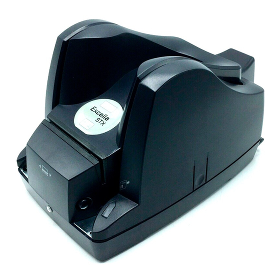
- Page 8 Figure 1-1. Excella STX viii...
-
Page 9: Section 1. Features And Specifications
Recognition) and dual-sided scanner with endorsement printer. The Excella STX is a single transaction Check Reader; one check is entered into the Excella STX at a time. The Excella STX reads the MICR character set (E13B or CMC7 fonts) on the front face and bottom of a check and... -
Page 10: Accessories
Excella STX Installation and Operation • Printed messages are programmable • Message height: 1/8” consisting of 12 pixels • Resolution: 200 dpi (scaling to 100 dpi); black/white and grayscale images • Image compression: CCITT G4 or JPEG • Image files: TIFF 6.0, JFIF with EXIF tags, BMP •... - Page 11 Section 1. Features and Specifications Table 1-1. Specifications OPERATING Check Reader Reference Standards ANSI X9.27 Power Input 24 VDC, 2.5 Amps Document Size 4”x 8.5” Maximum Printer/Cartridge Image Resolution: 200 dpi (scaling to 100 dpi); Black/white and grayscale images (color images are offered as an option) Image compression: CCITT G4 or JPEG...
- Page 12 Excella STX Installation and Operation...
-
Page 13: Section 2. Installation
2. Remove two covers and install 2 ink cartridges (the cartridges are shipped uninstalled) 3. Install Excella STX API/Demo software (CD provided by MagTek) 4. Connect interface cable (USB or Ethernet) and power cable to Excella STX 5. Connect power cord to AC wall outlet 6. -
Page 14: Outer Cover Removal
Excella STX Installation and Operation Outer Cover Removal To remove the Outer Cover, perform the following: 1. Using both hands, place two index fingers on the release buttons and two thumbs on the inner race of the Outer Cover as shown in Figure 2-1. (The left Release Button is shown; the Right Release Button is directly opposite.) -
Page 15: Center Cover Removal
Section 2. Installation Center Cover Removal To remove the Center Cover, perform the following: 1. Place the right-hand thumb and index finger on the front Release Buttons as indicated in Figure 2-2. 2. Place the index finger on the rear Release Button (not shown) as indicated in the illustration. (The location of the rear Release Button is shown in Figure 2-3.) 3. -
Page 16: Printer/Cartridge Installation And Removal
Excella STX Installation and Operation PRINTER/CARTRIDGE INSTALLATION AND REMOVAL Printer/Cartridge Installation To install the Printer/Cartridge, refer to Figure 2-4 and perform the following: 1. Ensure the printer latch is down and locate the guide pins on the Printer/Cartridge and the guide holes in the Printer Base (Inset). -
Page 17: Center Cover Replacement
Section 2. Installation Figure 2-4. Printer/Cartridge Installation and Removal Center Cover Replacement To replace the Center Cover, refer to Figures 2-2 and 2-3. 1. Tilt the front of the Cover up, and use the two guide pins, Figure 2-3 , near the rear of the unit to orient the Cover. -
Page 18: Cable Connections
Excella STX Installation and Operation CABLE CONNECTIONS The cable connections are shown in Figure 2-5. Figure 2-5. Cable Connections CABLING Cabling for Power Supply and Cords is as shown in Figure 2-6. Figure 2-6. Power Supply and Cords. P/N 64300098 and 71100001... - Page 19 Section 2. Installation The Cabling for the USB cable 22350300 is as shown in Figure 2-7. Figure 2-7. Cabling, USB, 4-pin, P/N 22350300 Cabling for the Ethernet P/N22350302 is shown in Figure 2-8. Figure 2-8. Cabling, Ethernet P/N22350302...
- Page 20 Excella STX Installation and Operation...
-
Page 21: Section 3. Operation And Maintenance
SECTION 3. OPERATION AND MAINTENANCE This section contains powering, operating, and maintenance procedures. Ensure the Excella is installed and cabling and power are connected as described in Section 2. POWER UP Plug the power supply, P/N 64300098P/N, and cord 71100001, into wall power, and press the start button. -
Page 22: Id Card Insertion
Excella STX Installation and Operation ID Card Insertion Enter ID cards for scanning with the front of the card facing the scan bar, as shown in Figure 3-2. The right exit port will flash when the ID card is requested. - Page 23 Section 3. Operation and Maintenance The location LED indicators are shown in Figure 3-4, and the descriptions are in Table 3-1. Figure 3-4. Location of LED Indicators Table 3-1. Description of LEDs Middle LED Description (Unit Status) Steady Green Power on, everything is OK Slow Blink Amber Cover open Fast Blink Red...
-
Page 24: Maintenance
Excella STX Installation and Operation MAINTENANCE Printer/Cartridge Cleaning The Installation and Removal of the Printer/Cartridges are shown and described in Section 2. Installation. Clean the Printer/Cartridge as follows: The Printer/Cartridges should be taken out when cleaned. See Section 2, Printer/Cartridge Installation and Removal. -
Page 25: Scan Bar Cleaning
Section 3. Operation and Maintenance Caution Do not wipe the electrical contact area. 4. If ink remains on the nozzle plate, wipe again with a clean dry cloth. Scan Bar Cleaning With the Outer and Center Covers removed, locate the Hinged Roller Tower and the Scanning Tower. - Page 26 Excella STX Installation and Operation 2. On the Exit side, pull the Tab up and the Scan Bar Tower down (to the right). Figure 3-7. Opening Right Scan Bar...
-
Page 27: Card And Check Path Cleaning
Section 3. Operation and Maintenance 3 Clean each Scan Bar with Cleaning Swab, P/N 97200078, as shown in Figure 3-8. Figure 3-8. Cleaning the Scan Bars Card and Check Path Cleaning Remove the Outside and Center Covers and open the Scan Bars as previously described. Remove larger debris, such as jammed checks or cards from the check and card paths. - Page 28 Excella STX Installation and Operation...
-
Page 29: Appendix A. Built-In Web Page
APPENDIX A. BUILT-IN WEB PAGE OVERVIEW Excella STX is a web appliance and it offers several functions and features in a built-in Web page accessible through a Web browser. For example, if Excella STX’s active device IP address is 192.168.160.2, type the “http://192.168.160.2” in your web browser to access Excella STX’s web page. -
Page 30: Maintenance
Excella STX Installation and Operation MAINTENANCE The Maintenance Page, Figure A-2, provides status and counters that can be useful to define maintenance service programs for Excella STX. Also, the device’s clock can be set on this page. Figure A-2. Maintenance Page CALIBRATE Scanner calibration is performed at the factory, and subsequent calibrations are NOT required under normal operating conditions. -
Page 31: Update Firmware
Appendix A. Built-in Web Page UPDATE FIRMWARE The Update Firmware Page, Figure A-3, is used to download new firmware to the Excella STX device. Firmware for Excella STX is provided in a file with the “.mef” extension. Figure A-3. Update Firmware Page... -
Page 32: Configuration
Caution Do not turn off power to Excella STX during the update process. If power is turned off, Excella STX will hang up and the unit may have to be returned to the factory. 4. When completed, the "Firmware Update" message will appear with information as follows: Filename = ms117x.mef... -
Page 33: Network Configuration Tab
The Excella STX device name provided to the DHCP server (the network server must be setup appropriately to use this option). This name must be unique for each Excella STX device on the network. The default factory value is “EX” followed by the unit’s S/N (e.g. EX-A03LEY9). -
Page 34: Ethernet Configuration Tab
Excella STX Installation and Operation Click on this button to save the current settings to the Excella STX device. Ethernet Configuration Tab Figure A-5. Ethernet Configuration Tab MAC Address The MAC (Media Access Control) address uniquely identifies each Excella STX device. This... - Page 35 Appendix A. Built-in Web Page IP Address This is Excella STX’s device IP address on the network. Use this option to change the IP address value. The default factory value is 192.168.10.100. Subnet Mask Use this option to change the Subnet Mask value. The default factory value is 255.255.255.0.
-
Page 36: Usb Configuration Tab
USB Configuration Tab Figure A-6. USB Configuration Tab IP Address This is Excella STX’s device IP address. Use this option to change the IP address value. The default factory value is 192.168.160.2 Subnet Mask Use this option to change the Subnet Mask value. The default factory value is 255.255.255.0. -
Page 37: Save/Restore Configuration Tab
“Cancel Changes” Button Click on this button to cancel the current settings being displayed on this page. “Save Settings” Button Click on this button to save the current settings to the Excella STX device. Save/Restore Configuration Tab Figure A-7. Save/Restore Configuration Tab... -
Page 38: Reset Device
Excella STX Installation and Operation “Select Config File” Box This option is used in conjunction with the “Restore” button. Use the “Browse” button to locate and select a previously saved config file, then click on “Restore” to activate the options saved in the Config file. -
Page 39: Appendix B. Usb Configuration Utility
APPENDIX B. USB CONFIGURATION UTILITY OVERVIEW MagTek’s “ExcellaUSBConfig” utility (Figure B-1) is used to configure Excella STX for the USB interface ONLY. The utility will automatically select and configure IP address for the PC and Excella STX. Note ExcellaUSBConfig must be run to establish a connection between the PC and Excella STX. -
Page 40: Device Address Setup
Excella STX Installation and Operation DEVICE ADDRESS SETUP Using My Computer go to the folder C:\Program Files\Magtek\Excella-STX Demo. • Run the ExcellaUSBConfig.exe program. • For Subnet Mask, Network Device ID and Excella Device, accept the defaults shown. • Click once on the Search button (this will automatically fill in valid IP addresses). -
Page 41: Appendix C. Check Reading
APPENDIX C. CHECK READING The characters printed on the bottom line of commercial and personal checks are special. They are printed with magnetic ink to meet specific standards. These characters can be read by a Excella Reader at higher speeds and with more accuracy than manual data entry. Two MICR character sets are used world wide;... -
Page 42: Check Layouts
Excella STX Installation and Operation The nonnumeric CMC-7 characters are translated by the Excella Reader as shown in Table C-1. Table C-1. CMC-7 Nonnumeric Characters CMC-7 Character MICRImage Reader Output SIII CHECK LAYOUTS Personal checks with MICR fields are shown in Figure C-1. Business checks are shown in Figure C-2. -
Page 43: Micr Fields
Appendix C. Check Reading 8.75” 3.67” Figure C-2. Business Checks MICR FIELDS The numbers 1 through 4 refer to the numbers below the checks on the illustration and represent the 4 MICR fields. 1-Transit Field The Transit field is a 9-digit field bracketed by two Transit symbols. The field is subdivided as follows: •... -
Page 44: 2-On-Us Field
Excella STX Installation and Operation 2-On-Us Field The On-Us field is variable, up to 19 characters (including symbols). Valid characters are digits, spaces, dashes, and On-Us symbols. The On-Us field contains the account number and may also contain a serial number (Check number) and/or a transaction code. Note that an On-Us symbol must always appear to the right of the account number. - Page 45 APPENDIX D. LICENSE AND COPYRIGHT The following documentation, license agreements, and copyright acknowledgments require no action on the part of the consumer and are included to comply with various disclosure requirements governing the use of components in the firmware development of Excella. GOAHEAD WEBSERVER limitation in the term "modification".) Each licensee is addressed as "you".
- Page 46 Excella STX Installation and Operation 12. IN NO EVENT UNLESS REQUIRED BY APPLICABLE LAW OR AGREED TO IN WRITING WILL ANY COPYRIGHT HOLDER, OR ANY OTHER PARTY WHO MAY MODIFY AND/OR and conditions. You may not impose any further restrictions on the recipients' exercise of the rights granted REDISTRIBUTE THE PROGRAM AS PERMITTED ABOVE, BE LIABLE TO YOU FOR DAMAGES, herein.
Need help?
Do you have a question about the EXCELLA STX and is the answer not in the manual?
Questions and answers