SmartRG SR350N User Manual
Broadcom chipset-based models
Hide thumbs
Also See for SR350N:
- User manual (7 pages) ,
- User manual (59 pages) ,
- User manual (65 pages)

Related Manuals for SmartRG SR350N


Summary of Contents for SmartRG SR350N
- Page 1 / GATEWAY USER MANUAL For all Broadcom Chipset-based models including: ADSL 3xx series: SR300n, SR350n, SR360n VDSL 5xx series: SR500n, SR505n, SR510n, SR550n Release 3.3 January, 2015...
-
Page 2: Table Of Contents
Manual Setup Model-specific variants: Network Authentication: Mixed WPA2/WPA-PSK MAC Filter Local Area Network (LAN) Setup Wireless Bridge Advanced Virtual Servers (Port Forward) Station Info Port Triggering Diagnostics DMZ Host SMARTRG INC. PROPRIETARY AND CONFIDENTIAL. ALL RIGHTS RESERVED. COPYRIGHT © 2014... - Page 3 Appendix A: Advanced Features Overview Connect-and-Surf (Automatic Broadband Con nection Configuration) Activation (Automatic ACS Connection Con figuration) TR-069 Remote Management: Automated Configuration Server Support Appendix B: Feature Comparison Matrix Revision History SMARTRG INC. PROPRIETARY AND CONFIDENTIAL. ALL RIGHTS RESERVED. COPYRIGHT © 2014...
-
Page 4: Introduction
Disclaimer SmartRG does not assume any liability arising out of the application or use of any products, or software described herein. Either does it convey any license under its patent rights nor patent rights of others. SmartRG further reserves the right to make changes to any products described herein without notice. -
Page 5: Safety Warnings
This transmitter must not be co-located or operating in conjunction with any other antenna or transmitter. SmartRG Inc declares that the WR100 is limited to operations on Channels 1 through 11, from 2400 to 2483.5 MHz by specified firmware controlled in the USA. -
Page 6: Welcome
Learn more at www.SmartRG.com. Purpose & Scope The purpose and scope of this document is to provide the customers of SmartRG with installation, configuration and monitoring information for all CPE platforms. Intended Audience The information in this document is intended for Network Architects, NOC Administrators, Field Service Technicians and other networking professionals responsible for deploying and managing broadband access networks. -
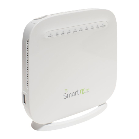
Page 7: Getting Familiar With Your Gateway
(See Appendix B for details) but the basic scheme of lights, ports and buttons represented in this section exist on each model. LED Status Indicators: Your SmartRG gateway has several indicator lights (LEDs) on its front panel. The number of DSL ports or USB ports may vary from model to model but generally, these indicators are available on all models:... -
Page 8: Connections
Connections: Below is a generic representation of a SmartRG gateway, however your specific model may have greater or fewer ports and controls across the back of the unit. Refer to the Quick Start Guide enclosed with your gateway for specifics regarding installation of your particular model. -
Page 9: Lan
SR360n, locate the WPS button on the top of the unit. For the SR350n and SR500n models, an exterior button is not present however WPS is supported via the on-board software. Reference the Quick Start Guide included with your gateway for specific instructions. -
Page 10: Wlan Button
Attach your computer's RJ45 connection to any of the SmartRG gateway's LAN ports (1-4). Configure your computer's IP interface to acquire an IP address using DHCP. (See the IMPORTANT note below for instructions on logging in to a SmartRG gateway configured for "bridge mode"... - Page 11 Controlfor details. If your SmartRG gateway is configured for "bridge mode" ( modem) operation, your PC will NOT be able to acquire an address via CPE's DHCP. Instead, manually configure your PC's interface with an IP address on the default network (e.g. 192.168.1.100).
-
Page 12: Device Info
The Device Info WAN status screen, provides a high level overview for the connection between your Internet Service Provider and the Gateway device, itself. The WAN interface could physically be DSL or Ethernet and supports a number of Layer 2 and above configuration options covered SMARTRG INC. PROPRIETARY AND CONFIDENTIAL. ALL RIGHTS RESERVED. COPYRIGHT © 2014... -
Page 13: Statistics
Some features are supported only on specific SmartRG models. These exceptions and are specified in this guide. The individual fields on this screen are defined as follows: Field Name Description Interface Displays the connection interface (layer 2 interface ( ) through which gateway handles the traffic.) -
Page 14: Wan Service
Reset Statistics button near the bottom of the screen to reset these counters. NOTE: Not all SmartRG gateway models support the SmartPort feature wherein a LAN port can be re-purposed to function as a WAN port (as displayed in the Interface column below note, LAN3, LAN2, LAN1, WAN.) Only models SR5xxn and SR360n support this functionality. -
Page 15: Xtm
Drops -(RX/ TX) total quantity of dropped packets Reset Statistics Resets the Statistics to zero. Device Info -> Statistics -> xTM displays the ATM/PTM statistics for your SmartRG Gateway. All WAN interfaces configured for your SmartRG gateway are included. Use the Reset button near the bottom of the screen to reset these counters. -
Page 16: Xdsl
DSL statistics for your SmartRG Gateway. All xDSL (VDSL or ADSL) interfaces configured for your SmartRG gateway are included. You are also able to reset these counters by selecting the Reset Statistics button located on the xTM screen as shown below. - Page 17 SNR Margin (db) (Downstream/Upstream) Signal to Noise Ratio Attenuation (db) (Downstream/Upstream) Estimate of average loop attenuation Output Power (dBm) (Downstream/Upstream) Transmit power from the gateway to the DSL loop. SMARTRG INC. PROPRIETARY AND CONFIDENTIAL. ALL RIGHTS RESERVED. COPYRIGHT © 2014...
- Page 18 (Path 0/1, Downstream/Upstream) Total number of Bit errors Total ES (Downstream/Upstream) Total number of Errored Seconds Total SES (Downstream/ Upstream) Total number of Severely Errored Seconds Total UAS (Downstream/Upstream) Total number of Unavailable Seconds SMARTRG INC. PROPRIETARY AND CONFIDENTIAL. ALL RIGHTS RESERVED. COPYRIGHT © 2014...
-
Page 19: Route
Route eDevice Info -> Route displays the LAN and WAN route table information configured in your SmartRG Gateway for both IPv4 and IPv6 implementation. The individual fields on this screen are defined as follows: Field Name Description Destination (Including IPv6 Route) Displays the Destination IP addresses. -
Page 20: Dhcp
DHCP Device Info -> DHCP displays a list of locally connected LAN hosts and their DHCP lease status, which are directly connected to the SmartRG Gateway via a LAN Ethernet port or Wireless LAN. The individual fields on this screen are defined as follows:... -
Page 21: Advanced Setup
The following screen will appear. When your desired settings have been declared, click the Apply/Save button to commit your changes. SMARTRG INC. PROPRIETARY AND CONFIDENTIAL. ALL RIGHTS RESERVED. COPYRIGHT © 2014... - Page 22 [LLC/SNAP-BRIDGING] Logical Link Control used to carry multiple protocols in a single PVC (Permanent Virtual Circuit). [VC/MUX] Virtual Circuit Multiplexer creates a virtual connection used to carry one protocol per PVC (Permanent Virtual Encapsulation Mode Circuit). SMARTRG INC. PROPRIETARY AND CONFIDENTIAL. ALL RIGHTS RESERVED. COPYRIGHT © 2014...
-
Page 23: Ptm Interface
PTM Interface The SmartRG gateway's VDSL2 standards support Packet Transfer Mode (PTM). An alternative to ATM mode, PTM transports packets (IP, PPP, Ethernet, MPLS, and others) over DSL links. Reference the IEEE802.3ah standard for Ethernet in the First Mile (EFM) for additional information. - Page 24 [1-0 Kbps] The shaping rate for the specified queue. Default Queue Shaping Rate [-1 Indicates no shaping.] Default Queue Shaping Burst [>= 1600] The maximum rate at which traffic can pass through the queue. Rate SMARTRG INC. PROPRIETARY AND CONFIDENTIAL. ALL RIGHTS RESERVED. COPYRIGHT © 2014...
-
Page 25: Eth Interface
Advance to the next after completing the required fields using the Next button appearing near the bottom of each screen. First, select the Layer2 interface to use for the WAN service. SMARTRG INC. PROPRIETARY AND CONFIDENTIAL. ALL RIGHTS RESERVED. COPYRIGHT © 2014... - Page 26 The individual fields on this screen are defined as follows: Field Name Description WAN service type [PPP over Ethernet PPPOE, IP over Ethernet IPoE, Bridging] Enter Service Description Enter a name to describe this configuration. SMARTRG INC. PROPRIETARY AND CONFIDENTIAL. ALL RIGHTS RESERVED. COPYRIGHT © 2014...
- Page 27 Since each data flow has its own queue, an ill-behaved flow (who has sent larger packets or more packets per second than the others since it became active) will only punish itself and not other sessions. Next, configure the PPP Username, Password and related information. SMARTRG INC. PROPRIETARY AND CONFIDENTIAL. ALL RIGHTS RESERVED. COPYRIGHT © 2014...
- Page 28 SMARTRG INC. PROPRIETARY AND CONFIDENTIAL. ALL RIGHTS RESERVED. COPYRIGHT © 2014...
- Page 29 MTU size [1370-1492] Edit the Maximum Transmission Units (MTU) for PPP service. Use Base MAC Address on this Use SmartRG Devices Base (Primary) MAC address. When unchecked a unique MAC per service is assigned. WAN interface Enable IPv6 Unnumbered Model...
- Page 30 Select DNS Server Interface from available WAN interfaces. Use the -> button to move your highlighted selection from left to right or <- to move your selection from right to left. SMARTRG INC. PROPRIETARY AND CONFIDENTIAL. ALL RIGHTS RESERVED. COPYRIGHT © 2014...
- Page 31 Alternatively, you may use the lower portion of the screen to manually key in static DNS IP addresses. Click Next after completing the desired parameters. Next, the summary screen will appear indicating that your PPPoE WAN setup is complete. SMARTRG INC. PROPRIETARY AND CONFIDENTIAL. ALL RIGHTS RESERVED. COPYRIGHT © 2014...
-
Page 32: Ip Over Ethernet
Advance to the next after completing the required fields using the Next button appearing near the bottom of each screen. First, select the Layer2 interface to use for the WAN service. SMARTRG INC. PROPRIETARY AND CONFIDENTIAL. ALL RIGHTS RESERVED. COPYRIGHT © 2014... - Page 33 Click the Next button to advance to the next step. Next, select the type of WAN service you wish to create. For this example choose IP over Ethernet. Click Next after completing the necessary fields. SMARTRG INC. PROPRIETARY AND CONFIDENTIAL. ALL RIGHTS RESERVED. COPYRIGHT © 2014...
- Page 34 Interface Association Identifier (IAID). A unique identifier for an IA, chosen by the client. (Optional) Option 61 DUID DHCP Unique Identifier (DUID) is used by the client to get an IP address from the DHCP server. SMARTRG INC. PROPRIETARY AND CONFIDENTIAL. ALL RIGHTS RESERVED. COPYRIGHT © 2014...
- Page 35 WAN Next-Hop IPv6 Address Enter the IP address of * For additional info see the SmartRG Support site’s knowledgebase. Enter the NAT Settings. No selections are required. All settings are optional. SMARTRG INC. PROPRIETARY AND CONFIDENTIAL. ALL RIGHTS RESERVED. COPYRIGHT © 2014...
- Page 36 Enable ULA Prefix Advertisement- Check this option to enable unique local address (ULA) advertisement on the LAN. Randomly Generate- Select this option to enable the gateway to generate a random IPv6 prefix. SMARTRG INC. PROPRIETARY AND CONFIDENTIAL. ALL RIGHTS RESERVED. COPYRIGHT © 2014...
-
Page 37: Ethernet Config
Make a manual selection from one of the latter four options when you have a specific device with a known limited transmission speed capability. Simply choose Auto and your SmartRG gateway will automatically select an appropriate setting based on Ethernet auto negotiation with the NIC of the LAN host. -
Page 38: Lan
Local Area Network (LAN) Setup Utilize this screen to configure the router’s local IP addresses, subnet mask, DHCP behavior and other related LAN side settings for your SmartRG Gateway. After selecting Advanced Setup -> LAN from the left navigation bar, customize the fields as desired. - Page 39 Subnet Mask Set the Subnet mask to be used by LAN devices connecting to this gateway. Enable your SmartRG gateway to listen to Internet Group Management Protocol (IGMP) network traffic Enable IGMP Snooping between hosts and routers. By listening to these conversations the gateway maintains a map of which links need which IP multicast streams.
-
Page 40: Nat
Enable LAN Side Firewall Enable the restriction of traffic between LAN hosts. The Dynamic Host Control Protocol Server (DHCP) functionality of your SmartRG gateway will automatically Enable / Disable DHCP Server assign LAN IP addresses to host devices as they connect with the gateway. Select Enable DHCP Server to take advantage of this feature. - Page 41 If your application does not appear in the preceding drop-down list you may manually enter a unique name for the Custom Service application. Server IP Address IP address of the LAN client in which the service has been hosted. External Port Start External Port to start with SMARTRG INC. PROPRIETARY AND CONFIDENTIAL. ALL RIGHTS RESERVED. COPYRIGHT © 2014...
-
Page 42: Port Triggering
Add button. Customize the fields as needed for the firewall pinholes you wish to establish. A maximum 96 entries can be configured. Click Apply/Save to commit your changes. SMARTRG INC. PROPRIETARY AND CONFIDENTIAL. ALL RIGHTS RESERVED. COPYRIGHT © 2014... -
Page 43: Dmz Host
[TCP, UDP, TCP/UDP] Select the protocol from the drop down list. DMZ Host The Broadband Router will forward IP packets from the WAN that do not belong to any of the applications configured in the Virtual Servers table SMARTRG INC. PROPRIETARY AND CONFIDENTIAL. ALL RIGHTS RESERVED. COPYRIGHT © 2014... -
Page 44: Security
Advanced Setup -> Security -> IP Filtering -> Outgoing from the left navigation bar, click the Add button. The following screen will appear to facilitate the filtering you desire. Click Apply/Save to commit the completed entry. SMARTRG INC. PROPRIETARY AND CONFIDENTIAL. ALL RIGHTS RESERVED. COPYRIGHT © 2014... - Page 45 Set the destination host port (or range of ports) for the above host (or range of hosts defined by optional routing Destination Port (port or "/prefix" s ubnet mask) to define the destination ports profile for which the filtered host egress traffic will be port:port) SMARTRG INC. PROPRIETARY AND CONFIDENTIAL. ALL RIGHTS RESERVED. COPYRIGHT © 2014...
-
Page 46: Ip Filtering - Incoming
Enter source address for rule. Enter source port number or range. Source Port (port or port:port) (Destination port numbers xxxxx:yyyyy). Select All checkbox Check as applicable to apply rule to all interfaces. SMARTRG INC. PROPRIETARY AND CONFIDENTIAL. ALL RIGHTS RESERVED. COPYRIGHT © 2014... -
Page 47: Mac Filtering
Check as applicable for desired rule. MAC Filtering Your SmartRG gateway can block or forward packets based on the originating device. This MAC filtering feature is available only in Bridging mode. For other modes, similar functionality is available via IP Filtering. -
Page 48: Parental Control
Applies the filter to the selected interface(s). Parental Control The Parental Control features of your SmartRG gateway enable restriction of Internet access on a LAN host by LAN host basis. This is achieved without the need for client software to be installed on each host. -
Page 49: Time Restriction
Filtering" f eatures Cisco Prime Home™ and not from this native, gateway user interface. Next click the button toward the center of the screen. The following screen will appear: SMARTRG INC. PROPRIETARY AND CONFIDENTIAL. ALL RIGHTS RESERVED. COPYRIGHT © 2014... -
Page 50: Quality Of Service
The stand-alone modem capability does not maintain a unique Allow and Block List for each individual LAN device. Some additional flexibility however is available when your SmartRG gateway is under management of Cisco Prime Home™. Refer to Cisco documentation regarding, "Content Filtering" f or instructions. -
Page 51: Qos Queue Config
NOTE: An default DSCP Mark of value Default(000000) will mark all egress packets that do NOT match any classification. QoS Queue Config Use the QoS Queue Config to configure a queue and add it to a selected Layer2 interface. SMARTRG INC. PROPRIETARY AND CONFIDENTIAL. ALL RIGHTS RESERVED. COPYRIGHT © 2014... - Page 52 Dropdown selection for priority value to be associated with QoS queue defined (e.g. 1(SP), 2(SP), 3(SP), 4 Queue Precedence (SP|WRR|WFQ)). Note: Lower value = higher priority The following selections are exposed only if SP|WRR|WFQ Queue Precedence priority as defined above is selected. SMARTRG INC. PROPRIETARY AND CONFIDENTIAL. ALL RIGHTS RESERVED. COPYRIGHT © 2014...
-
Page 53: Qos Classification
Advanced Setup -> Quality Of Service -> QoS Classification, click the button. The following screen will appear. A maximum of 32 entries can be configured. Click the Apply/Save button to commit your changes. SMARTRG INC. PROPRIETARY AND CONFIDENTIAL. ALL RIGHTS RESERVED. COPYRIGHT © 2014... - Page 54 [IP, ARP, IPV6] Select the Ethernet interface type for this classification. Source MAC Address Enter the source MAC Address and Source MAC Mask applied to classification. Source MAC Mask SMARTRG INC. PROPRIETARY AND CONFIDENTIAL. ALL RIGHTS RESERVED. COPYRIGHT © 2014...
-
Page 55: Qos Port Shaping
QoS Port Shaping facilitates setting a fixed rate (Kbps) for each of the Ethernet ports. Select Advanced Setup -> Quality Of Service -> QoS Port Shaping and the following screen will appear. Click the Apply/Save button to commit the changes entered. SMARTRG INC. PROPRIETARY AND CONFIDENTIAL. ALL RIGHTS RESERVED. COPYRIGHT © 2014... -
Page 56: Routing
The individual fields on this screen are defined as follows: Field Name Description Each line item in the table represents one of the Ethernet LAN ports on the back of your SmartRG Interface gateway. Type [LAN, WAN] Describes the function for which each physical port is configured on the gateway. -
Page 57: Static Route
Destination IP address desired (/prefix length if needed) Metric (optional) [>=0] Establishes traffic priority/weighting. Policy Routing Policy routing makes somewhat automated routing choices based on net admin dictated policies. For example, a network administrator might SMARTRG INC. PROPRIETARY AND CONFIDENTIAL. ALL RIGHTS RESERVED. COPYRIGHT © 2014... -
Page 58: Rip (Routing Information Protocol)
15) allowed in order to prevent routing loops. This can sometimes limit the size of networks that RIP can be successfully employed. After selecting Advanced Setup -> Routing -> RIP, click the button and the following screen will appear. Click the Apply/Save button to commit the changes entered. SMARTRG INC. PROPRIETARY AND CONFIDENTIAL. ALL RIGHTS RESERVED. COPYRIGHT © 2014... -
Page 59: Dns
Use the features of this screen to input the Domain Name Server information supplied by the service provider. After selecting Advanced Setup -> DNS -> DNS Server from the left navigation bar, the following screen will appear. Enter your desired settings. Click Apply/Save to commit changes. SMARTRG INC. PROPRIETARY AND CONFIDENTIAL. ALL RIGHTS RESERVED. COPYRIGHT © 2014... - Page 60 Alter this field only if IPv6 environment. Primary IPv6 DNS Server Enter the IP address of the primary IPv6 primary DNS. Secondary IPv6 DNS Server Enter the IP address of the primary IPv6 primary DNS. SMARTRG INC. PROPRIETARY AND CONFIDENTIAL. ALL RIGHTS RESERVED. COPYRIGHT © 2014...
-
Page 61: Dynamic Dns
The following screen will appear. Enter your desired settings then click Apply/Save to commit your changes. A maximum of 10 static DNS entries can be added. SMARTRG INC. PROPRIETARY AND CONFIDENTIAL. ALL RIGHTS RESERVED. COPYRIGHT © 2014... -
Page 62: Dsl
After selecting Advanced Setup ->DSL from the left navigation bar, click the button. The following screen will appear. Enter your desired settings then click Apply/Save to commit your changes. SMARTRG INC. PROPRIETARY AND CONFIDENTIAL. ALL RIGHTS RESERVED. COPYRIGHT © 2014... - Page 63 Max Upstream: 0.5 Mbps ANSI T1.413 Issue 2 standard T1.413 Max Downstream: 8 Mbps Max Upstream: 1.0 Mbps ITU-T G.992.3 standard. ADSL2 Max Downstream: 12 Mbps Max Upstream: 1.0 Mbps SMARTRG INC. PROPRIETARY AND CONFIDENTIAL. ALL RIGHTS RESERVED. COPYRIGHT © 2014...
- Page 64 No Retrain will not retrain even if the signal is lost. Puts the DSL modem in the L3 power state. Click the Apply button place the gateway in test mode. SMARTRG INC. PROPRIETARY AND CONFIDENTIAL. ALL RIGHTS RESERVED. COPYRIGHT © 2014...
-
Page 65: Dsl Bonding
DSL Bonding NOTE: This feature supported only on SmartRG models SR550n and SR552n. Bonding enables two DSL lines to feed the same modem. Utilize this screen to leverage the bandwidth of both lines. Bonded, they will behave as a single, higher bandwidth connection. -
Page 66: Upnp
IP cameras, printers and others. After selecting Advanced Setup -> UPnP from the left navigation bar. The following screen will appear. Check the checkbox to enable UPnP. Click Apply/Save to commit your changes. SMARTRG INC. PROPRIETARY AND CONFIDENTIAL. ALL RIGHTS RESERVED. COPYRIGHT © 2014... -
Page 67: Dns Proxy
The following screen will appear. Check the check-box to enable DNS Proxy mode and specify a Host-name and Domain Name of the LAN in the fields that follow. Click Apply/Save to commit your changes. SMARTRG INC. PROPRIETARY AND CONFIDENTIAL. ALL RIGHTS RESERVED. COPYRIGHT © 2014... -
Page 68: Interface Grouping
4. If this interface is to share the WAN interface, click the Shared WAN Interface box. Not checking this will cause the WAN interface you select to be removed from any other interface groups. SMARTRG INC. PROPRIETARY AND CONFIDENTIAL. ALL RIGHTS RESERVED. COPYRIGHT © 2014... -
Page 69: Ip Tunnel
Your changes will be effective immediately. IP Tunnel IP Tunneling is typically used as a means to establish a path between two independent networks. Your SmartRG gateway supports connecting islands of IPv6 networks across the IPv4 internet or IPv4 in IPv6 as well. -
Page 70: Ipv4Inipv6
4. AFTR (Address Family Transition Router) may be configured automatically. Select the Manual radio button to specify your desired value for fields. Click Apply/Save to commit your changes. SMARTRG INC. PROPRIETARY AND CONFIDENTIAL. ALL RIGHTS RESERVED. COPYRIGHT © 2014... -
Page 71: Ipsec
Add New Connection. The following screen will appear. Enter your connection details by completing the appropriate fields. Click Apply/Save to commit your changes. SMARTRG INC. PROPRIETARY AND CONFIDENTIAL. ALL RIGHTS RESERVED. COPYRIGHT © 2014... - Page 72 Enter the WAN IP for tunnel. [Subnet, Single Address] Select IP information for site A and B. Tunnel Access From Local IP Addresses Subnet indicates entire LAN. For single host, select Single Address. SMARTRG INC. PROPRIETARY AND CONFIDENTIAL. ALL RIGHTS RESERVED. COPYRIGHT © 2014...
-
Page 73: Certificate
Complete the necessary fields. The screen shown on the next page will appear. Enter your connection details by completing the appropriate fields. SMARTRG INC. PROPRIETARY AND CONFIDENTIAL. ALL RIGHTS RESERVED. COPYRIGHT © 2014... - Page 74 2. Paste the Certificate details as indicated between the BEGIN markers. 3. Paste the Private Key information as indicated between the BEGIN markers. Click Apply to commit this Certificate. SMARTRG INC. PROPRIETARY AND CONFIDENTIAL. ALL RIGHTS RESERVED. COPYRIGHT © 2014...
-
Page 75: Trusted Ca
BEGIN markers. Click Apply to commit this Certificate. After adding one certificate, a Remove button will be revealed on the Trusted CA landing page. SMARTRG INC. PROPRIETARY AND CONFIDENTIAL. ALL RIGHTS RESERVED. COPYRIGHT © 2014... -
Page 76: Multicast
Select Advanced Setup -> Multicast from the left navigation bar. The screen pictured below will appear. Update or complete the necessary fields. Click Apply to commit your changes. SMARTRG INC. PROPRIETARY AND CONFIDENTIAL. ALL RIGHTS RESERVED. COPYRIGHT © 2014... - Page 77 Enter a value for the maximum number of seconds for the range of random values a host can pick to count down from. The value must be greater than the Query Interval. If using IGMP v1, this value is fixed at 10 seconds. SMARTRG INC. PROPRIETARY AND CONFIDENTIAL. ALL RIGHTS RESERVED. COPYRIGHT © 2014...
-
Page 78: Basic
Wi-Fi network name (also known as SSID) and restrict the channel set based on country requirements. After selecting Wireless -> Basic from the left navigation bar you may modify settings as desired. Click Apply/Save to commit your settings. SMARTRG INC. PROPRIETARY AND CONFIDENTIAL. ALL RIGHTS RESERVED. COPYRIGHT © 2014... - Page 79 Hide Access Point Check to Hide Access Point SSID. Check to prevent LAN client devices from communicating with one another on the Client Isolation wireless network. SMARTRG INC. PROPRIETARY AND CONFIDENTIAL. ALL RIGHTS RESERVED. COPYRIGHT © 2014...
-
Page 80: Security
Authorized MAC are empty, becomes the default value. Hide Access Point is enabled or the MAC filter list is empty with "allow" c hosen, WPS2 will be disabled. SMARTRG INC. PROPRIETARY AND CONFIDENTIAL. ALL RIGHTS RESERVED. COPYRIGHT © 2014... - Page 81 [Configured, Unconfigured] Select Configured to have the gateway assign security settings to clients. Select Set WPS AP Mode Unconfigured when you wish to have an external client assign security settings to your SmartRG gateway. Device PIN (Auto generated by the access point.) Network Authentication Select the desired network security authentication type.
-
Page 82: Manual Setup - Network Authentication: Open And Shared
[1-4] Select which of the four keys from the list is presently in effect. Enter up to four encryption keys using the on-screen instructions to achieve the desired security strength Network Key 1-4 (128 or 64 bit). SMARTRG INC. PROPRIETARY AND CONFIDENTIAL. ALL RIGHTS RESERVED. COPYRIGHT © 2014... -
Page 83: Manual Setup - Network Authentication: 802.1X
[1-4] Select which of the four keys from the list is presently in effect. Enter up to four encryption keys using the on-screen instructions to achieve the desired security strength Network Key 1-4 (128 or 64 bit). SMARTRG INC. PROPRIETARY AND CONFIDENTIAL. ALL RIGHTS RESERVED. COPYRIGHT © 2014... -
Page 84: Manual Setup - Network Authentication: Wpa
[AES, TKIP+AES] Choose from Advanced Encryption Standard (AES) or AES combined with Temporary Key WPA/WAPI Encryption Integrity Protocol (TKIP). This field has been pre-populated with the option most complimentary to the Network Authentication selected. Manual Setup - Network Authentication: WPA-PSK SMARTRG INC. PROPRIETARY AND CONFIDENTIAL. ALL RIGHTS RESERVED. COPYRIGHT © 2014... -
Page 85: Manual Setup - Network Authentication: Wpa2
Enter up to four encryption keys using the on-screen instructions to achieve the desired security strength Network Key 1-4 (128 or 64 bit). Manual Setup - Network Authentication: WPA2 The individual fields on this screen are defined as follows: SMARTRG INC. PROPRIETARY AND CONFIDENTIAL. ALL RIGHTS RESERVED. COPYRIGHT © 2014... -
Page 86: Manual Setup - Network Authentication: Wpa2-Psk
Enter up to four encryption keys using the on-screen instructions to achieve the desired security strength Network Key 1-4 (128 or 64 bit). Manual Setup - Network Authentication: WPA2-PSK SMARTRG INC. PROPRIETARY AND CONFIDENTIAL. ALL RIGHTS RESERVED. COPYRIGHT © 2014... -
Page 87: Manual Setup - Network Authentication: Mixed Wpa2-Wpa
The individual fields on this screen are defined as follows: Field Name Description Select the SSID from the drop-down list for the wireless network to which this security configuration will Select SSID apply. WPA2 Preauthentication SMARTRG INC. PROPRIETARY AND CONFIDENTIAL. ALL RIGHTS RESERVED. COPYRIGHT © 2014... -
Page 88: Manual Setup
Enter up to four encryption keys using the on-screen instructions to achieve the desired security strength Network Key 1-4 (128 or 64 bit). Manual Setup Network Authentication: Mixed WPA2/WPA-PSK SMARTRG INC. PROPRIETARY AND CONFIDENTIAL. ALL RIGHTS RESERVED. COPYRIGHT © 2014... -
Page 89: Mac Filter
Next, select the MAC Restrict Mode (Disabled, Allow or Deny). Use the button to add a MAC address to the filter list. Click Apply/Save to commit the completed entry. SMARTRG INC. PROPRIETARY AND CONFIDENTIAL. ALL RIGHTS RESERVED. COPYRIGHT © 2014... -
Page 90: Wireless Bridge
Click Refresh to update the remote bridges. Wait for few seconds to update. Click Apply/Save to commit your changes. SMARTRG INC. PROPRIETARY AND CONFIDENTIAL. ALL RIGHTS RESERVED. COPYRIGHT © 2014... -
Page 91: Advanced
RTS threshold, the wakeup interval for clients in power-save mode, and more. After selecting Wireless -> Advanced from the left navigation bar, enter your settings as desired. Click Apply/Save to commit your changes. SMARTRG INC. PROPRIETARY AND CONFIDENTIAL. ALL RIGHTS RESERVED. COPYRIGHT © 2014... - Page 92 20MHz bands. [Upper, Lower] Select the appropriate sideband to minimize RF interference from adjacent channels and Control Sideband maximize the throughput. Sideband controls only available in 40MHz mode. SMARTRG INC. PROPRIETARY AND CONFIDENTIAL. ALL RIGHTS RESERVED. COPYRIGHT © 2014...
- Page 93 [256 - 2346 bytes] Specify the Request to Send packet size beyond which the WLAN client hardware invokes its RTS Threshold RTS/CTS mechanism. Smaller packets will otherwise be sent not using RTS/CTS. The threshold is off when using the default setting of 2347. SMARTRG INC. PROPRIETARY AND CONFIDENTIAL. ALL RIGHTS RESERVED. COPYRIGHT © 2014...
-
Page 94: Station Info
This page displays authenticated wireless stations and their status. Diagnostics Line performance diagnostic tools are supported by your SmartRG gateway. Three legs of the data path are included in the available tests: LAN connectivity, DSL connectivity and Internet connectivity tests. -
Page 95: Diagnostics
Diagnostics -> Fault Management from the left navigation bar, select values for the Maintenance Domain (MD) Level, Destination MAC Address to test and enter the applicable (if any) 802.1Q VLAN ID. SMARTRG INC. PROPRIETARY AND CONFIDENTIAL. ALL RIGHTS RESERVED. COPYRIGHT © 2014... -
Page 96: Management Settings
Current settings for your gateway can be backed up to a file stored on your computer. After selecting Management -> Settings -> Backup from the left navigation bar, the following screen will appear. Select the type of backup you desire. SMARTRG INC. PROPRIETARY AND CONFIDENTIAL. ALL RIGHTS RESERVED. COPYRIGHT © 2014... -
Page 97: Update
Choose File button for the type of setting you wish to restore. Next, browse to the desired .conf file located on your personal computer. Lastly, click the Update button. SMARTRG INC. PROPRIETARY AND CONFIDENTIAL. ALL RIGHTS RESERVED. COPYRIGHT © 2014... -
Page 98: Restore Default
After selecting Management -> Settings -> Restore Default from the left navigation bar, the following screen will appear. Click the Restore Default Settings button. SMARTRG INC. PROPRIETARY AND CONFIDENTIAL. ALL RIGHTS RESERVED. COPYRIGHT © 2014... -
Page 99: System Log
The individual fields on this screen are defined as follows: Action Description View System Log This button will display the system log. Configure System Log This button will edit the system log SMARTRG INC. PROPRIETARY AND CONFIDENTIAL. ALL RIGHTS RESERVED. COPYRIGHT © 2014... -
Page 100: Security Log
Control where log events will be sent. Choose 'Remote' or 'Both' to send to the specified IP address and UDP port of Mode a remote syslog server. Choose 'Local' or 'Both' to record events in the local memory of your SmartRG gateway. Security Log The security log contains a history of events related to sensitive access to the gateway. -
Page 101: Management Server
TR-069 Client SmartRG gateways support TR-069 based standards for remote management. Utilize this screen to configure the gateway with details about the management ACS (Auto Configuration Server) to which this gateway will be linked. - Page 102 Description Select whether to use the base MAC address or the serial number of your gateway when connecting to the ACS. (Optional) For SmartRG gateways bearing firmware version 2.5.0.2 and above: Set the modem’s TR-069 client to report Serial Number instead of MAC address to the ACS.
- Page 103 Refer to your ACS platform documentation for details. While 30005 is the default value for SmartRG gateways, some ACS product’s Management Servers may require a different value for remote management. SmartRG products have technology to accommodate such requirements for several ACS products:...
-
Page 104: Stun Config
Description Character limit is 256 characters and represents the physical STUN server’s assigned network address. An invalid address will produce an immediate on-screen error message from the SmartRG gateway. STUN Server Address Note that an ACS server may also have STUN functionality running on the same physical box. Please consult your ACS vendor for implementation options and also TR-069 protocol documentation, if necessary. -
Page 105: Internet Time
Network Time Protocol. You may select or input your own NTP servers. Select the desired time zone for the gateway. Click Apply/Save to commit your settings. SMARTRG INC. PROPRIETARY AND CONFIDENTIAL. ALL RIGHTS RESERVED. COPYRIGHT © 2014... -
Page 106: Access Control
Utilize this screen to establish a Service Control List. You many control which services (FTP, HTTP, Telnet, etc.) are to be restricted on the LAN After selecting Management -> Access Control -> Services you may modify settings as desired. Click Apply/Save to commit your settings. SMARTRG INC. PROPRIETARY AND CONFIDENTIAL. ALL RIGHTS RESERVED. COPYRIGHT © 2014... -
Page 107: Passwords
Establish or alter the passwords associated with access to the Gateway. Three accounts are available to manage: Admin, Support and User. After selecting Management -> Passwords you enter your desired settings for one login. SMARTRG INC. PROPRIETARY AND CONFIDENTIAL. ALL RIGHTS RESERVED. COPYRIGHT © 2014... -
Page 108: Update Software
Re-enter the desired new password exactly as entered for the previous field. Update Software Utilize this feature to update the firmware of your SmartRG gateway. Software updates for SmartRG product are available for download by direct customers of SmartRG via the SmartRG Customer Portal. -
Page 109: Reboot
Occasional troubleshooting measures may require that the router be rebooted. The reboot function is located on this screen. Select Managment -> Reboot from the left lavigation bar. The following screen will appear. SMARTRG INC. PROPRIETARY AND CONFIDENTIAL. ALL RIGHTS RESERVED. COPYRIGHT © 2014... -
Page 110: Appendix A: Advanced Features Overview
NOTE: If you prefer to configure your SmartRG's WAN interface manually, connect a laptop to any of the LAN ports and follow the instructions in the "Logging in to Your SmartRG Gateway" a nd "Remote Managemen" s ections of this User Manual. Do not connect the WAN interface cable until after the configuration is completed. - Page 111 SmartRG works closely with industry-leading, TR-069 automated configuration server (ACS) solutions providers to ensure "plug-n-play" interoperability. See following table. Calix Compass/Consumer Connect ACS In addition to being Calix physical layer certified (to ensure Calix access equipment compatibility), SmartRG gateways have been tested to confirm maximum interoperability with the Calix Compass/Consumer Connect ACS solution.
-
Page 112: Appendix B: Feature Comparison Matrix
Appendix B: Feature Comparison Matrix SmartRG residential gateways combine WAN connectivity with a firewall-protected router and industry-leading TR-069 remote management support. Most variants provide 802.11n Wi-Fi connectivity, as well. See the model-specific, SmartRG feature details below: Broadband LAN Device Managed... -
Page 113: Revision History
6/26/2014 Authored complete field-by-field descriptions for each screen Complete compendium of screen-shots for each feature Migrated use case content to on-line knowledge base. (See the SmartRG Customer Portal.) Visual overhaul. New colors, logo and layout. 10/20/2014 Added missing sections for Ethernet Config and LAN.
Need help?
Do you have a question about the SR350N and is the answer not in the manual?
Questions and answers