Table of Contents
Advertisement
Advertisement
Table of Contents

Subscribe to Our Youtube Channel
Related Manuals for SmartRG SR10


Summary of Contents for SmartRG SR10
- Page 1 SmartRG™ Residential Gateways November 15th, 2012 Version 2.4...
-
Page 2: Table Of Contents
Configuring the Layer 2 Interface (VDSL/PTM with VLAN Tags) ............. 23 Creating the WAN Service ........................24 Use Case: Provisioning Your SmartRG for Remote ACS Management ..........28 Use Case: Setting Up the LAN ........................29 Use Case: Setting Up Wireless ........................31 Use Case: Setting Up Wireless Distribution System (WDS) .............. - Page 3 Use Case: Applying Quality of Service (QoS) to VoIP and IPTV LAN Traffic ........47 Use Case: Configuring IP Security (IPSec) in Support of VPNs ............54 Managing Your SmartRG™ Gateway ......................57 Save, Restore or Default Configurations ....................57 Update Software ............................
- Page 4 SmartRG™ Residential Gateways List of Figures Figure 1 SmartRG Front Panel LEDs ......................10 Figure 2 SR10 Rear Panel Connectors ......................12 Figure 3 SR100 Rear Panel Connectors ..................... 12 Figure 4 SR350N Rear Panel Connectors ....................13 Figure 5 SR350NE Rear Panel Connectors ....................13 Figure 6 SR500N/NE Rear Panel Connectors ....................
- Page 5 Introduction Figure 41 QoS: IPTV Queue Configuration ....................49 Figure 42 QoS Queue Enable ........................50 Figure 43 QoS VoIP Classifier Configuration ....................51 Figure 44 QoS IPTV Classifier Configuration ....................52 Figure 45 QoS VoIP and IPTV Classifier Configurations ................53 Figure 46 Time Zone and NTP Server Settings ..................
-
Page 6: Introduction
SmartRG™ Residential Gateways Introduction This document describes the features, functions and administration of SmartRG™ residential gateways. Who Should Read This User’s Manual The information in this document is intended for Network Architects, NOC Administrators, Field Service Technicians and other networking professionals responsible for deploying and managing broadband access networks. -
Page 7: Smartrg™ Residential Gateways
If you prefer to configure your SmartRG’s WAN interface manually, connect a laptop to any of the LAN ports and follow the instructions in the “Logging in to Your SmartRG™ Gateway” and “Use Case: Creating WAN Connections for Internet Access and Remote Management”... -
Page 8: Tr-069 Remote Management - Automated Configuration Server Support
SmartRG works closely with industry-leading, TR-069 automated configuration server (ACS) solutions providers to ensure “plug-n-play“ interoperability. Affinegy ACS SmartRG gateways have been tested to confirm maximum interoperability with the Affinegy ACS solution. Calix Compass/Consumer Connect ACS In addition to being Calix physical layer certified (to ensure Calix access equipment compatibility), SmartRG gateways have been tested to confirm maximum interoperability with the Calix Compass/Consumer Connect ACS solution. -
Page 9: Smartrg™ Product Family
Contact SmartRG Support for detailed descriptions and management of the features listed above. S m a r t R G © 2 0 1 2 C o n f i d e n t i a l... -
Page 10: Front Panel Leds
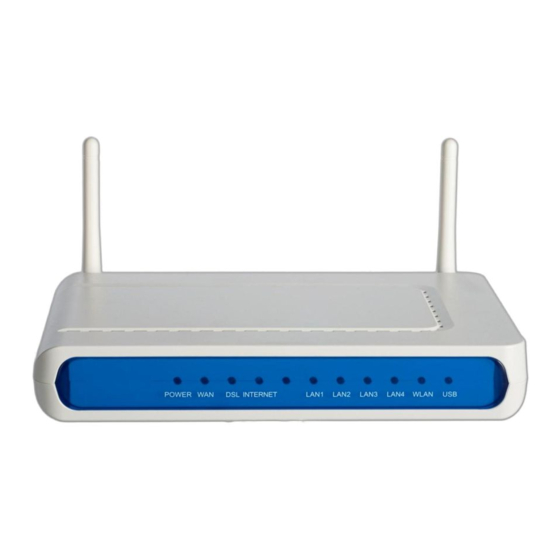
SmartRG™ Residential Gateways Front Panel LEDs The SmartRG’s front panel LEDs can be useful for troubleshooting and diagnostic purposes: Figure 1 SmartRG Front Panel LEDs P a g e | 10 C o n f i d e n t i a l... - Page 11 SmartRG™ Residential Gateways The SmartRG front panel LEDs are defined as follows: Power ON: Power is on OFF: Power is off WAN (SR500N/NE) ON: Ethernet WAN Active OFF: No link ON: Link established and active OFF: No link Blinking: Training mode...
-
Page 12: Rear Panel Connectors
SmartRG™ Residential Gateways Rear Panel Connectors SR10 DSL(WAN) Reset On/Off Power Figure 2 SR10 Rear Panel Connectors SR100 DSL(WAN) LAN1 - 4 Reset Power On/Off Figure 3 SR100 Rear Panel Connectors P a g e | 12 C o n f i d e n t i a l... -
Page 13: Sr350N
SmartRG™ Residential Gateways SR350N DSL(WAN) LAN1 - 4 Power On/Off (Reset on bottom) Figure 4 SR350N Rear Panel Connectors SR350NE Ethernet(WAN) LAN1 - 3 Power On/Off (Reset on bottom) Figure 5 SR350NE Rear Panel Connectors S m a r t R G © 2 0 1 2... -
Page 14: Sr500N/Sr500Ne
SmartRG™ Residential Gateways SR500N/SR500NE DSL(WAN) GigE(WAN) LAN1 - 4 Reset USB On/Off Power Figure 6 SR500N/NE Rear Panel Connectors SR505N DSL(WAN) LAN1 - 4 WPS Reset Power On/Off USB(Side) Figure 7 SR505N Rear Panel Connectors P a g e | 14 C o n f i d e n t i a l S m a r t R G ©... -
Page 15: Logging In To Your Smartrg™ Gateway's Ui
Logging in to Your SmartRG™ Gateway’s UI To manually configure the SmartRG access the gateway’s embedded web UI: 1. attach your computer’s RJ45 connection to any of the SmartRG’s LAN ports (1-4) 2. configure your computer’s IP interface to acquire an IP address using DHCP... -
Page 16: Navigating Your Smartrg Gateway's Web Ui
SmartRG™ Residential Gateways Navigating Your SmartRG Gateway’s Web UI At login the Device Info page will appear. In addition to the basic identification info shown, the Device Info menu item can be expanded (by clicking the text) to reveal: ... - Page 17 SmartRG™ Residential Gateways The remainder of the left menu bar items can be navigated in a similar fashion. Configure the following features and functions by expanding: Advanced Setup – WAN & LAN interfaces, routing, interface groupings, QoS, security, etc.
-
Page 18: Configuring Your Smartrg™ - Common Use Cases
Enabling secure communications (IPSec) Given the breadth of a SmartRG residential gateway’s features and the diversity of applications, only the most common use cases are detailed here. Please contact SmartRG Support to inquire about additional use cases. Use Case: Creating WAN Connections for Internet Access and Remote... -
Page 19: Configuring The Layer 2 Interface (Ethernet)
Configuring Your SmartRG™ - Common Use Cases Figure 10 Internet / TR-069 Management WAN Connection WAN connection creation is a two-step process beginning with the configuration of a layer 2 interface (Ethernet or DSL) followed by the creation of a layer 3, WAN service. Common WAN services include PPPoE, DHCP and Static IP. -
Page 20: Configuring The Layer 2 Interface (Ethernet With Vlan Tags)
SmartRG™ Residential Gateways No further configuration is necessary. Configuring the Layer 2 Interface (Ethernet with VLAN Tags) In some applications it may be necessary to segment the Ethernet WAN interface into separate VLANs. A common application for a VLAN segmented WAN interface is bridged IPTV as detailed in the “Bridged IPTV Configuration”... -
Page 21: Configuring The Layer 2 Interface (Adsl)
Configuring Your SmartRG™ - Common Use Cases Configuring the Layer 2 Interface (ADSL) To configure an ADSL layer 2 interface: 1. Select Advanced Setup -> Layer2 Interface and click Add. Figure 13 ADSL Layer 2 Interface Configuration 2. Enter the PVC’s identifier (VPI/VCI). -
Page 22: Configuring The Layer 2 Interface (Ptm - Supported On Adsl And Vdsl)
SmartRG™ Residential Gateways IMPORTANT - Check “Enable Quality of Service” if you intend to support QoS classified traffic through the WAN service. 8. Click Apply/Save. NOTE Enabling QoS for routed IPTV service configurations will improve channel change performance. Configuring the Layer 2 Interface (PTM – Supported on ADSL and VDSL) To configure a PTM layer 2 interface : 1. -
Page 23: Configuring The Layer 2 Interface (Vdsl/Ptm With Vlan Tags)
Configuring Your SmartRG™ - Common Use Cases IMPORTANT - Check “Enable Quality of Service” if you intend to support QoS classified traffic through the WAN service. 6. Click Apply/Save. NOTE Enabling QoS for routed IPTV service configurations will improve channel change performance. -
Page 24: Creating The Wan Service
SmartRG™ Residential Gateways Creating the WAN Service WAN Services are created on top of previously created Layer 2 interfaces. To create a WAN service: 1. Select Advanced Setup -> WAN Service and click Add. 2. Select a previously created layer 2 interface from the drop down list and click Next. -
Page 25: Figure 16 Ppp Username And Password
Configuring Your SmartRG™ - Common Use Cases 5. For PPP WAN services enter the “PPP Username” and “PPP Password”. If desired, enable the firewall, NAT and IGMP Proxy. Click Next. Figure 16 PPP Username and Password -OR- S m a r t R G © 2 0 1 2... -
Page 26: Figure 17 Wan Ip Settings
SmartRG™ Residential Gateways 6. For IPoE WAN services select “Obtain an IP address automatically” (DHCP) or select “Use the following Static IP address” and enter the “WAN IP Address”, “WAN Subnet Mask” and “WAN gateway IP.” Click Next. Figure 17 WAN IP Settings 7. -
Page 27: Figure 18 Wan Nat, Firewall And Igmp Settings
Configuring Your SmartRG™ - Common Use Cases Figure 18 WAN NAT, Firewall and IGMP Settings 8. Select the WAN interface to be used by this WAN service. Click Next. 9. Select “Obtain DNS info from a WAN interface” and select the desired WAN interface from the drop down list (a single WAN interface is common unless you are creating bridged IPTV configurations) –or- select “Use the following Static DNS IP address”... -
Page 28: Use Case: Provisioning Your Smartrg For Remote Acs Management
Use Case: Provisioning Your SmartRG for Remote ACS Management NOTE This step is not required for production SmartRG gateways. SmartRG maintains an “Activation Server” that associates MAC addresses with service providers’ ACS management URLs. After the SmartRG has established its WAN connection (using the Connect-and-Surf algorithm) it connects to the SmartRG Activation Server and reports its MAC. -
Page 29: Use Case: Setting Up The Lan
Configuring Your SmartRG™ - Common Use Cases today. See us at www.smartrg.com. Use Case: Setting Up the LAN To configure the SmartRG’s LAN interface: 1. Select Advanced Setup -> LAN Figure 20 LAN Settings 2. Leave the “GroupName” as Default. -
Page 30: Figure 21 Adding Dhcp Static Ip Leases
SmartRG™ Residential Gateways Figure 21 Adding DHCP Static IP Leases 8. Enter the LAN host’s “MAC Address” and the desired “IP Address.” 9. Click Apply/Save and repeat steps 7 and 8 for all static IP LAN hosts. P a g e... -
Page 31: Use Case: Setting Up Wireless
4. Select the “Country” from the dropdown list. 5. Click Apply/Save. NOTE The SmartRG provides support for 3 additional guest/virtual wireless access points. S m a r t R G © 2 0 1 2 C o n f i d e n t i a l... -
Page 32: Figure 23 Wireless - Security Settings
SmartRG™ Residential Gateways 6. If you would like to select a specific Wi-Fi channel (1-11), select Wireless -> Advanced and change the Channel setting. The default value is “Auto.” 7. Select Wireless -> Security Figure 23 Wireless - Security Settings 8. -
Page 33: Use Case: Setting Up Wireless Distribution System (Wds)
Two or more SmartRG gateways can be configured for WDS operation. The example below depicts a WDS deployment with three SmartRG gateways in a large home or office – one primary gateway in the center of the building and one remote gateway at either end of the building. - Page 34 1. On the primary SmartRG gateway: configure the routed WAN connection following the instructions in the “Use Case: Creating WAN Connections for Internet Access and Remote Management” section. 2. On the remote SmartRG gateway(s): no WAN configuration is required as the WAN connection is unused. To configure the LAN interfaces…...
-
Page 35: Use Case: Creating Iptv Service Configurations
Configuring Your SmartRG™ - Common Use Cases Use Case: Creating IPTV Service Configurations The SR350N, SR350NE, SR500N and SR500NE SmartRG gateways are designed to meet the demands of IPTV service deployments. Typically IPTV services have been deployed using bridged architectures with public IP addresses assigned to the IPTV Set-top-boxes (STBs) connected to the gateway’s LAN ports. -
Page 36: Bridged Iptv Configuration
SmartRG™ Residential Gateways SmartRG gateways are designed to exceed the high bandwidth demands of either IPTV service architecture. Refer to the appropriate section below to configure the SmartRG gateway for your particular IPTV deployment architecture. Bridged IPTV Configuration A bridged IPTV configuration is comprised of: ... -
Page 37: Creating Bridged Wan Connections
Configuring Your SmartRG™ - Common Use Cases Creating Bridged WAN Connections To configure the SmartRG for bridged IPTV service deployments (with one or more WAN connections) start by creating the bridged WAN connections: 1. Create a Layer 2 interface following the instructions detailed in: a. -
Page 38: Figure 29 Creating A Bridged Wan Service
SmartRG™ Residential Gateways 4. Select “Bridging” and click Next. Figure 29 Creating a Bridged WAN Service 5. Review the bridged WAN service summary and click Apply/Save if you are satisfied. 6. Repeat steps 1-5 as necessary to support your particular IPTV configuration (i.e. single or multi-WAN connection). -
Page 39: Figure 30 Iptv Layer 2 Interface Summary (Multi-Wan Bridge Group)
Configuring Your SmartRG™ - Common Use Cases At the conclusion of step 9 your Layer 2 Interface summary (Advanced Setup -> Layer 2 Interface) will look similar to: Figure 30 IPTV Layer 2 Interface Summary (Multi-WAN Bridge Group) NOTE The generalized (more complex) IPTV bridge group is detailed here. The majority of DSLAMs require only a single WAN connection to support IPTV services. -
Page 40: Figure 31 Iptv Wan Service Summary (Multi-Wan Bridge Group)
SmartRG™ Residential Gateways Your WAN Service summary (Advanced Setup -> WAN Service) will look similar to: Figure 31 IPTV WAN Service Summary (Multi-WAN Bridge Group) P a g e | 40 C o n f i d e n t i a l... -
Page 41: Creating Interface (Bridge) Groupings
Configuring Your SmartRG™ - Common Use Cases Creating Interface (Bridge) Groupings 10. Select Advanced Setup -> Interface Grouping. Figure 32 Creating an IPTV Bridge Interface Group S m a r t R G © 2 0 1 2 C o n f i d e n t i a l... -
Page 42: Figure 33 Defining An Iptv Bridge Interface Group
SmartRG™ Residential Gateways 11. Click Add. Figure 33 Defining an IPTV Bridge Interface Group P a g e | 42 C o n f i d e n t i a l S m a r t R G © 2 0 1 2... -
Page 43: Figure 34 Typical Iptv Bridge Interface Group
Configuring Your SmartRG™ - Common Use Cases 12. Enter the “Group Name.” 13. Highlight the bridged “WAN Interfaces” to be included in the bridge group and click <-. 14. Highlight the LAN Interfaces to be included in the bridge group and click <-. -
Page 44: Creating Vendor Id Based Interface (Bridge) Groupings
15. Click Apply/Save. Creating Vendor ID Based Interface (Bridge) Groupings To provide greater flexibility when connecting set-top-boxes to LAN ports SmartRG gateways support “Vendor ID Based” bridge groupings. Instead of adding specific LAN ports to the bridge group, you can specify the Vendor ID of the set-top-box. Any traffic received on any LAN port containing the specified Vendor ID will be bridged to the designated bridged WAN connection. -
Page 45: Routed Iptv Configuration (Single Wan Connection)
LAN (e.g. Internet data, IPTV and VoIP) as detailed in, “Use Case: Applying Quality of S.” NOTE The SmartRG family of gateways employs “Differentiated Services” (RFC 2474) to provide IP traffic QoS. When configuring QoS for various traffic categories the following Differentiated Services Code Point (DSCP) values or suggested: ... -
Page 46: Routed Iptv Configuration (Multiple Wan Connections)
WAN connection, routed IPTV service configuration is shown below. Figure 37 Routed IPTV Configuration (Multiple WAN Connection) To configure the SmartRG for multi-WAN connection, routed IPTV service deployments, follow the single WAN connection, routed IPTV configuration instructions above –plus- add bridged WAN connections using the instructions detailed in, “Creating Bridged WAN Connections.”... -
Page 47: Use Case: Applying Quality Of Service (Qos) To Voip And Iptv Lan Traffic
(e.g Internet data and file transfers). Time critical traffic commonly includes SIP signaling (VoIP call setup/teardown) and IGMP signaling (IPTV channel change). The SmartRG line of gateways prioritizes time critical traffic using the “Differentiated Services Code Point” field in the IP header as defined by RFC 2474. -
Page 48: Figure 39 Enable Smartrg Qos Processing
SmartRG™ Residential Gateways To configure the SmartRG’s QoS feature: 1. Ensure the layer 2 WAN interface “Enable Quality of Service” check box is checked as detailed in the Layer 2 Interface configuration sections. 2. Select Advanced Setup -> Quality of Service -> QoS Config Figure 39 Enable SmartRG QoS Processing 3. -
Page 49: Figure 41 Qos: Iptv Queue Configuration
Configuring Your SmartRG™ - Common Use Cases 5. Name, enable and select the WAN interface to be fed by this queue. IMPORTANT Select the routed WAN interface created in the “Creating the WAN Service” section. NOTE 6. Select a “Precedence” of 1. -
Page 50: Figure 42 Qos Queue Enable
SmartRG™ Residential Gateways 11. Leave the “DSL Latency” value set to Path0 and Click Apply/Save. NOTE The default data queue depicted in the QoS architecture diagram above does not need to be specifically created. 12. Enable the newly created queues by selecting Advanced Setup -> Quality of Service -> QoS Queue Config, check the “Enable”... -
Page 51: Figure 43 Qos Voip Classifier Configuration
Configuring Your SmartRG™ - Common Use Cases 13. Create the VoIP traffic classifier by selecting Advanced Setup -> Quality of Service -> QoS Classification and click Add. Figure 43 QoS VoIP Classifier Configuration 14. Set the Name, Rule Order, and enable the classifier rule. -
Page 52: Figure 44 Qos Iptv Classifier Configuration
SmartRG™ Residential Gateways 15. Select an “Ether Type” of IP (0x800). 16. Enter the source MAC and Mask values in 01:02:03:04:05:06/FF:FF:FF:00:00:00 format. 17. Assign the Classification Queue (identified by WAN interface&Precedence&Path). 18. Click Apply/Save. 19. Create the IPTV traffic classifier by selecting Advanced Setup -> Quality of Service -> QoS Classification and click Add. -
Page 53: Figure 45 Qos Voip And Iptv Classifier Configurations
Configuring Your SmartRG™ - Common Use Cases 21. Select an “Ether Type” of IP (0x800). 22. Enter the “Differentiated Service Code Point (DSCP) Check” value. NOTE AF21 (DSCP18) is common for Mediaroom STBs. 23. Assign the Classification Queue (identified by WAN interface&Precedence&Path). -
Page 54: Use Case: Configuring Ip Security (Ipsec) In Support Of Vpns
SmartRG™ Residential Gateways Use Case: Configuring IP Security (IPSec) in Support of VPNs IP Security (IPSec) is a suite of IETF standards developed to provide data integrity and privacy, key management and data authentication at the IP layer. Typically IPSec is deployed to create Virtual Private Networks (VPNs) between communicating peers. - Page 55 Configuring Your SmartRG™ - Common Use Cases To configure IPSec in the SmartRG gateway: 1. Select Advanced Setup -> IPSec 2. Click Add New Connection and then click Show Advanced Settings to bring up the following screen: 3. Enter a name for the IPSec connection.
- Page 56 SmartRG™ Residential Gateways header by encapsulating it in an additional IP header. The outer IP header remains unprotected. 5. Enter the IP address of the tunnel’s remote IPSec gateway. 6. Select either a single IP address or a subnet of IP addresses for the local end of the IPSec tunnel.
-
Page 57: Managing Your Smartrg™ Gateway
Managing Your SmartRG™ Gateway M anag ing Your SmartRG ™ Gateway Save, Restore or Default Configurations To save the existing gateway configuration to your hard drive: 1. Select Management -> Settings -> Backup. 2. Click Backup xxx Settings. NOTE Two types of settings are available for backup: Running Settings: settings governing the gateway’s operation at the present time... -
Page 58: Update Software
SmartRG™ Residential Gateways Update Software To update the gateway’s software: 1. Select Management -> Update Software. 2. Browse to find the new gateway software on your hard drive (ex: CA_2.4.3.7_24282_SR500N_fs_kernel) 3. Click Update Software. NOTE The software update process takes approximately 2 minutes to complete. Do NOT power cycle the gateway until the software update process has completed. -
Page 59: Configure Time Settings
Managing Your SmartRG™ Gateway Configure Time Settings To set the gateway’s time zone and NTP server settings: 1. Select Management -> Internet Time. 2. Select your time zone from the drop down list. 3. (Optional) Select the first, second … NTP servers from the drop down lists. (A custom NTP server can be configured by selecting “Other”... -
Page 60: Configure Access Controls (Http, Telnet, Ssh, Etc.)
SmartRG™ Residential Gateways Configure Access Controls (HTTP, Telnet, SSH, etc.) To enable/disable gateway management services such as HTTP, Telnet and SSH: 1. Select Management -> Access Control -> Services. Figure 47 Enabling/Disabling HTTP, Telnet, SSH... Access 2. Enable/disable LAN and/or WAN access to the various management services as desired . -
Page 61: Configure User Logins
Managing Your SmartRG™ Gateway Configure User Logins SmartRG gateways support the following user roles: admin – unrestricted access by a PC connected to a LAN port support – unrestricted access by an ISP technician connected through the managed WAN interface To change user passwords: 1. -
Page 62: Reset The Gateway
IMPORTANT Pressing the reset switch for more than 10 seconds causes the SmartRG gateway to reset into its boot image rendering the gateway non-functional. This condition can be detected by: ... -
Page 63: Troubleshooting
Troubleshooting Troubleshooting Accessing System Logs To configure the System Log for use during troubleshooting efforts: 1. Select Management -> System Log. 2. Click Configure System Log. Figure 48 Configuring the System Log for Use In Troubleshooting 3. Select the “Log Level” from the drop down list. “Debugging” provides the greatest level of log detail. -
Page 64: Executing Diagnostics
Monitoring traffic on the WAN interface can be difficult as intervening equipment between the access gear and the gateway is necessary to provide a monitoring point for your work station. To simplify WAN traffic monitoring SmartRG gateways provide the capability of “mirroring” WAN traffic to any of the gateway’s Ethernet LAN ports. -
Page 65: Contacting Smartrg Technical Support
Contacting SmartRG Technical Support Contacting SmartRG Technical Support For technical support contact: Support Monday – Friday, 5am-6pm Pacific Time (UTC-8:00) 1-360-859-1780 1-877-486-6210 (Toll free from the US & Canada) support@smartrg.com S m a r t R G © 2 0 1 2...
Need help?
Do you have a question about the SR10 and is the answer not in the manual?
Questions and answers