Table of Contents
Advertisement
SIDE-POWER
Thruster Systems
Installation and user manual
SLEIPNER MOTOR AS
P.O. Box 519
N-1612 Fredrikstad
Norway
Tel: +47 69 30 00 60
Fax: +47 69 30 00 70
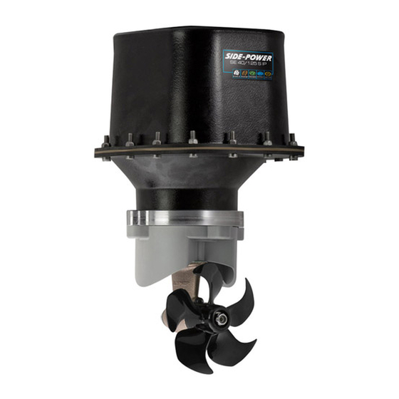
SE 40/125 S IP
Ignition Protected
thruster assembly
w w w . s i d e - p o w e r . c o m
s i d e p o w e r @ s l e i p n e r. n o
© Sleipner Motor AS version 1.3 - April 2014
Advertisement
Table of Contents

Related Manuals for Side-Power SE 40/125 S IP


Summary of Contents for Side-Power SE 40/125 S IP
- Page 1 SE 40/125 S IP Ignition Protected SIDE-POWER thruster assembly Thruster Systems Installation and user manual SLEIPNER MOTOR AS P.O. Box 519 N-1612 Fredrikstad Norway Tel: +47 69 30 00 60 w w w . s i d e - p o w e r . c o m Fax: +47 69 30 00 70 s i d e p o w e r @ s l e i p n e r.
-
Page 2: Table Of Contents
Shearpin between electro-motor and driveshaft protects electromotor and gearsystem if propeller gets jammed. jammed. If original Side-Power panel is used, the panel shuts off automatically 6 minutes after last use. If original Sidepower panel is used, the panel shuts off automatically 6 minutes after last use. -
Page 3: Planning And Important Precautions
Planning and important precautions Prior to installation, it is important that the installer reads this guide to ensure necessary acquaintance with this product. The electromotor assembly must be handled carefully. Do not put it down on the driveshaft. Beware to keep installation within advised measurements. We advice to paint the gear leg and propellers with antifouling. -
Page 4: Bolt On Installation
PS ! Take care with grinders as it is very easy to remove to If you are installing the standard Side-Power dual joystick much in fibreglass panel this is already secured. -
Page 5: Mould On Installation
4. Offer the stern tunnel to the desired position on the transom tery banks. and mark around the tube. If you are installing the standard Side-Power dual joystick panel this is already secured. 5. Cut the marked hole in the transom of the boat. -
Page 6: Gearhouse And Motorbracket
Fig. 1 Fig. 2 Bolt tightening forces: Bolts (2x) holding gearhouse to bracket: 17 Nm (12,4 lb/ft) Designed by Material Type Date Drawing nr Tolerance NS-ISO 2768-1 R. Hansen SM-101539 13.09.2011 Copyright All rights reserved Title SL E IP N E R M O T O R A S Part nr Weight Size... -
Page 7: Oil Tank & Propellers
Fig. 1 Thread glue Fitting propellers 1. Push the propeller on to the shaft and turn until the internal spline in the propeller hub aligns with the external spline on the propeller shaft. 2. Push the propeller onto the shaft with the track for the drivepin in an horizontal position (same direction as you set the drivepin), all the way in. -
Page 8: Electromotor Ip Assembly
Fig. 2 Fig. 1 Designed by Material Type Date Drawing nr Tolerance NS-ISO 2768-1 R. Hansen SM-101539 13.09.2011 Designed by Material Type Date Drawing nr Tolera R. Hansen 13.09.2011 SM-101539 Copyright All rights reserved Title Copyright All rights reserved Title SL E IP N E R M O T O R A S SLE IPN E R M O TO R A S Part nr... -
Page 9: Electrical Installation
RED: Battery Date Drawing nr Designed by Material Type Tolerance NS-ISO 2768-1 R. Hansen 30.08.2011 SM-101462 Battery & cable recommendations: Copyright All rights reserved Title Model Voltage Nominal Min. battery >7m total + & - 7-14m total + & - 15-21m total + &... -
Page 10: Control Panel And Control-Leads
• When using original Side-Power equipment it is all "plug & go". • When using original Sidepower equipment it is all "plug & go". -
Page 11: "Visual" Wiring Diagram
"Visual" wiring diagram "Visual" wiring diagram SE 40/125S ignition protected thruster assembly version 1.3 - April 2014 SP55S2i ignition protected thruster assembly 1.1 - 2006... -
Page 12: Technical Wiring Diagram
Technical wiring diagram Round 4 pin connector on motor Motor housing connector Fused blue 9 red (+) inside 1A (sig -) blue (sig +) Electronic interface box 6 1232i white black (-) grey (sig +) grey (sig -) black brown Battery Fuse main... -
Page 13: Checklist
Checklist Propeller is fastened correctly to the shaft. Propeller turns freely in tunnel. The anode holding screw is tightened well with thread glue. There is a sturdy additional support under the electric motor, taking the weight load of the electromotor assembly away ... -
Page 14: Important User Precautions
Important user precautions Ensure that you know the location and how to operate the main battery switch and that disconnects the thruster from all power sources (batteries) so that the thruster can be turned off in case of a malfunction. ... -
Page 15: How To Use Sidepower Thrusters
2. Please take some time to exercise thruster usage in open water to avoid damages to your boat. 3. Turn the control panel on by pushing both "ON" buttons on the original Side-Power panel simultaneously. If another type of control is 3. -
Page 16: Maintenance
Electromotor assembly Composite 5-blade propeller for ultimate performance. Pre-filled lifetime lubricated gearhouse. Changeable anode protects gearhouse from corrosion in seawater. Thread glue Fastening screw for anode Anode Propeller lock nut Washer Drivepin for propeller Maintenance » Keep the propeller and gearhouse clean from growth by painting with antifouling before every season. PS ! The anode, sealing and propeller shafts must absolutely not be painted. -
Page 17: Troubleshooting
Troubleshooting Before seeking assistance at the help desk of your Sidepower dealer / distributor please perform these tests and make notes of all measurements to ensure that they have as much information as possible to work on. NB! All check points and solutions must be carried out after consulting the relevant information elsewhere in this manual to under- stand how the system is intended to work. -
Page 18: Warranty Statement
Warranty statement 1. The equipment manufactured by Sleipner Motor AS (The “Warrantor”) is warranted to be free from defects in workmanship and mate- rials under normal use and service. 2. This Warranty is in effect for of two years from the date of purchase by the user. Proof of purchase must be included, to establish that it is inside the warranty period. -
Page 19: Parts List
SP 40 S2i PARTS LIST - SE 40/125 S SP 30 S2i / SP 40 S2i / SP 55 S2i SE 40/125S ignition protected thruster assembly 3.7 - 2006 version 1.3 - April 2014... -
Page 20: Service Centres
Worldwide sales and service www.side-power.com SLEIPNER MOTOR AS P.O. Box 519 N-1612 Fredrikstad Norway Tel: +47 69 30 00 60 Fax:+47 69 30 00 70 www.side-power.com sidepower@sleipner.no...
Need help?
Do you have a question about the SE 40/125 S IP and is the answer not in the manual?
Questions and answers