Table of Contents

Related Manuals for Side-Power SE 30/125S2 IP


Summary of Contents for Side-Power SE 30/125S2 IP
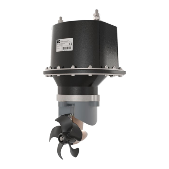
- Page 1 SE 30/125S2 IP Ignition Protected SIDE-POWER thruster assembly Thruster Systems Installation and user manual SLEIPNER MOTOR AS P.O. Box 519 N-1612 Fredrikstad Norway www.side-power.com Document id: 5453 Revision: © Sleipner Motor AS 2018...
-
Page 2: Table Of Contents
Control panel and control-leads..........18 Visual wiring diagram .............. 19 Technical wiring diagram ............20 Checklist .................. 21 Important user precautions ............22 How to use Side-Power thrusters ..........23 Maintenance ................24 Troubleshooting ............... 25 Warranty statement ..............26 Parts list ................... 27 Service centres ............... -
Page 3: Technical Specifications
Electronic time-lapse device protects against sudden change of drive direction. Electric thermal cut-off switch in electromotor protects against over heating (auto reset when electro motor cools down). Flexible coupling between electro-motor and driveshaft protects electromotor and gear system if propeller gets jammed. If original Side-Power panel is used, the panel shuts Bow Thruster off automatically 6-9 minutes after last use. -
Page 4: Planning & Important Precautions
Planning and important precautions Prior to installation, it is important that the installer reads this guide to ensure necessary acquaintance with this product. The electromotor assembly must be handled carefully. Do not put it down on the driveshaft. Beware to keep installation within advised measurements. We advice to paint the gearhouse and propellers with antifouling. - Page 5 Fig. 1 Pivot Fig. 3 point B = 10,0m A = 11,0m Fig. 2 Fig. 4 Ø Positioning of the tunnel / thruster Plassering av tunnel og thruster Positioning of the tunnel / thruster Positionierung von Tunnel / Thruster The Thruster should be as far forward as possible (Fig. 1) Tunnelen bør plasseres lengst mulig frem i baugen (Fig.
- Page 6 30 - 40% of the total thrust. NB! Propellene til Side-Power thrustere kaviterer ikke på arbeid- wodurch das benötigte Vakuum nicht zustande kommt. This "free" additional thrust can in optimal installations be as Diese Schubkraft kann bei optimaler Installation bis zu 30-40% shastighet, så...
- Page 7 Fig. 1 Fig. 2 R = 0,1 x D (10%) R = 0,1 x D (10%) � � � � � ☺ ☺ ☺ ☺ ☺ Fig. 3 Fig. 4 Prevent drag from tunnel Tunnel ends Formgebung der Tunnelenden Motstand forårsaket av tunnel Rounded tunnel ends will maximize thrust and minimize Abgerundete Tunnelenden erhöhen die Schubkraft und A possible problem in sailboats or fast powerboats, is that they...
- Page 8 Fig. 1 � � � � � ☺ ☺ ☺ ☺ ☺ Pos. A Pos. B � � � � � ☺ ☺ ☺ ☺ ☺ Tunnel installasjon på seilbåter Tunnel installation in sailboats Installation in Segelbooten Tunnel installation in sailboats Many sailboats have a racing type hull which means that it is very fl at bot- Many sailboats have a racing type hull which means that it is very Mange seilbåtskrog er bygget for å...
- Page 9 Fig. 1 � � � � � ☺ ☺ ☺ ☺ ☺ Pos. A Pos. B � � � � � ☺ ☺ ☺ ☺ ☺ Tunnel installation in sailboats Installation in Segelbooten Many sailboats have a racing type hull which means that it is very Segelboote weisen häufig einen Rumpf in Rennform auf, was Fig.
- Page 10 Fig. 1 Fig. 2 Radius = D x 0,1 a1 a2 a1 a2 Fig. 3 Fig. 4 Series production installation Installasjon ved serieproduksjon Boat builders having thrusters as standard, or delivering a large Båtbyggere som har trustere som standard eller leverer en eller portion of one or more models with thrusters, have the opportu- fl ere modeller med valgfri truster i stort antall har mulighet for å...
-
Page 11: Tunnel Installation
Fig. 2 Fig. 1 Fig. 4 Fig. 3 Tunnel installation Tunnelinstallering We recomend that a professional does the fi breglass fi tting Sleipner Motor anbefaler at innstøping av glassfi bertunnelen of the tunnel. These instructions are only general, and do not utføres av kyndig personell. - Page 12 NB ! Original Sidepower tunnel sind in ausgeliefertem NB ! All original Sidepower tunnels are fully waterproof NB ! Alle originale Side-Power tunneler er vanntette ved Zustand absolut wasserdicht. when they are delivered.
- Page 13 If this is not so, then the area on the transom will have to be If you are installing the standard Side-Power dual joystick flattened to ensure a snug fit. panel this is already secured.
-
Page 14: Gearhouse And Motorbracket
Fig. 1 Fig. 3b Fig. 1 Fig. 4a Port Starboard Fig. 2 Fig. 5 BOATS CENTRELINE Fig. 4b Fig. 2 TUNNELS SP30S2i CENTRELINE SP40S2i Ø 8,5mm 0,33" Bolt tightening forces (2x): Ø 27,5mm 20,5mm Fig. 6 1,08" DIN 931 - M 8x55 A2 = 0,81"... - Page 15 Fig. 1 Fig. 2 Fitting propeller Montering av propell Før propellen på akslingen, påse at spline i propellen passer på Push the propeller on to the shaft and turn until the internal spline på aksling. Fig 1. spline in the propeller hub aligns with the external spline on the propeller shaft.
- Page 16 New drivepin, artnr: 141285 - pin Ø4 x 32 Coupling, artnr: 140992 Works on: SE50 and SE60 New enginebracket for SE60, artnr: SM-136297 With reinforced ribs and space for the coupling Fig. 1c Fig. 1 Fig. 3 The coupling is complete with the gear pin to the gearleg. So, there's only a new pin on the engine.
-
Page 17: Electrical Installation
Ba�ery RED + Thruster motor Isolation cap Red + (IP model) Isolation cap Battery & cable recommendations: Battery & cable recommendations: Tegninger for å illustrere ba�erikabel -lengder <7m total 7-14m total 15-21m total 22-28m total 28-35m total 36-45m total + & - Nominal current Min. -
Page 18: Control Panel And Control-Leads
• When using original Side-Power equipment it is all "plug & go". • If the drive direction of the thruster is the opposite of what expected, the blue and grey wire must be changed on each panel. -
Page 19: "Visual" Wiring Diagram
"Visual" wiring diagram Visuelt Koblingsskjema With Automatic Main Switch: 6 1278-xxM 5-LEAD CONTROL CABLE 6 1278-xxM 5-LEAD CONTROL CABLE STERN 6 1265 5-LEAD Y-CONNECTOR 6 1265 5-LEAD Y-CONNECTOR STERN Switch Switch STERN 5A fuse 5A fuse 6 1278-xxM 5-LEAD 6 1278-xxM 5-LEAD CONTROL CABLE CONTROL CABLE 6 1277-xxM 4-LEAD... -
Page 20: Technical Wiring Diagram
Technical wiring diagram Round 4 pin connector on motor Motor housing connector Fused blue 9 red (+) inside 1A (sig -) blue (sig +) Electronic interface box 6 1232i white black (-) grey (sig +) grey (sig -) black brown Battery Fuse main... -
Page 21: Checklist
Checklist Propeller is fastened correctly to the shaft. Propeller turns freely in tunnel. The anode holding screw is tightened well with thread glue. All electrical wiring, cable sizes and battery capacity is according to the thruster installation manual. ... -
Page 22: Important User Precautions
Important user precautions Important user precautions Viktige brukerforebehold Viktige brukerforebehold • Ensure that you know the location of the main battery switch that • Ensure that you know the location of the main battery switch that • • Forviss deg om at du kjenner plasseringen av hovedstrømsbryteren Forviss deg om at du kjenner plasseringen av hovedstrømsbryteren disconnects the thruster from all power sources (batteries) so that disconnects the thruster from all power sources (batteries) so that... -
Page 23: How To Use Side-Power Thrusters
2. Please take some time to exercise thruster usage in open waterto avoid damages to your boat. 3. Turn the control panel on by pushing both “ON” buttons on the original Side-Power panel simultaneously. If another type of control is installed, en gage the On/Off switch for the bowthruster. -
Page 24: Maintenance
1.Fastening screw for anode 2. Anode 3. Propeller lock nut 4. Washer 5. Flexible coupling Maintenance » Re-tighten the bolts holding the gearhouse to the motor bracket during the first on-land service with the specified bolt tightening force (see page 13). »... -
Page 25: Troubleshooting
Troubleshooting Before seeking assistance at the help desk of your Sidepower dealer / distributor please perform these tests and make notes of all measurements to ensure that they have as much information as possible to work on. NB! All check points and solutions must be carried out after consulting the relevant information elsewhere in this manual to under- stand how the system is intended to work. -
Page 26: Warranty Statement
Warranty statement 1. The equipment manufactured by Sleipner Motor AS (The “Warrantor”) is warranted to be free from defects in workmanship and materials under normal use and service. 2. This Warranty is in eff ect for of two years (Leisure Use) or one year (Commercial use) from the date of purchase by the user. Proof of purchase must be included, to establish that it is inside the warranty period. - Page 27 SPARE PARTS In order to present the most up to date documentation, we advise you to go to our website www.side-power.com and locate your product to fi nd relevant spare parts. SE 30/125S2 ignition protected thruster assembly 5453-2 - 2018...
- Page 28 Worldwide sales and service www.side-power.com SLEIPNER MOTOR AS P.O. Box 519 N-1612 Fredrikstad Norway The information given in the document was correct at the time it was published. However, Sleipner Motor AS can not accept liability for any inaccuracies or omissions it may contain.
Need help?
Do you have a question about the SE 30/125S2 IP and is the answer not in the manual?
Questions and answers