Table of Contents
Advertisement
Quick Links
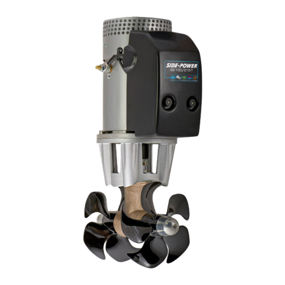
SIDE-
POWER
Thruster systems
Installation and user's manual
GB
Installasjons og brukermanual
N
SLEIPNER MOTOR AS
P.O. Box 519
N-1612 Fredrikstad
Norway
Tel:
Fax:
+47 69 30 00 60
+47 69 30 00 70
SE 120/215T
SE 150/215T
w w w . s i d e - p o w e r . c o m
s i d e p o w e r @ s l e i p n e r. n o
© Sleipner Motor AS 2007
Advertisement
Table of Contents


Need help?
Do you have a question about the SE 120/215T and is the answer not in the manual?
Questions and answers