Table of Contents
Advertisement
Advertisement
Table of Contents

Subscribe to Our Youtube Channel
Related Manuals for Jeanneau VELASCO 43 F


Summary of Contents for Jeanneau VELASCO 43 F
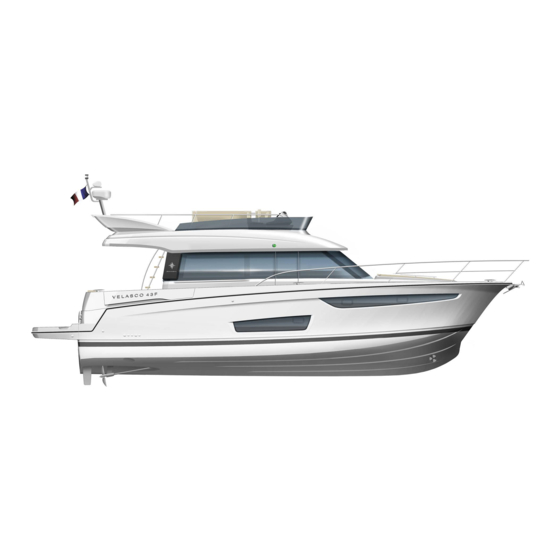
- Page 1 VELASCO 43 F OWNER'S MANUAL 164060 Index A...
-
Page 3: Table Of Contents
CONTENTS INTRODUCTION ........................7 Welcome ......................... 7 Notes on reading this manual..................9 TECHNICAL SPECIFICATIONS ................... 11 1.1 CONSTRUCTION ......................11 1.2 GENERAL DIMENSIONS....................11 1.3 ENGINE ......................... 11 1.4 ELECTRICITY........................ 11 1.5 CAPACITIES ......................... 12 DESIGN CATEGORIES AND DISPLACEMENT ............13 2.1 DESIGN CATEGORIES.................... - Page 4 INFORMATION RELATING TO FIRE RISKS AND RISKS OF EXPLOSION ....39 6.1 PROPULSION ENGINES AND OTHER FUEL-BURNING EQUIPMENT......39 6.2 ELECTRICAL SYSTEM ....................39 6.3 GAS SYSTEM ........................ 39 6.4 FIRE-PREVENTION AND FIRE-FIGHTING EQUIPMENT ..........40 6.4.1 Fire-fighting equipment ..................40 6.4.2 Automatic fire extinguishing system..............
- Page 5 10 AUDIO-VISUAL EQUIPMENT..................107 10.1 TELEVISION ....................... 107 10.2 HIFI..........................109 11 ONBOARD COMFORT ....................111 11.1 AIR CONDITIONING ....................111 11.2 ELECTRONIC EQUIPMENT ..................120 11.3 EQUIPMENT OTHER THAN FOR PROPULSION, WHICH BURNS FUEL (GENERATOR, HEATING)..................124 11.3.1 General points ....................124 11.3.2 Generator ......................
- Page 6 14 STEERING SYSTEM ....................175 14.1 GENERAL POINTS ..................... 175 14.2 LAYOUT DIAGRAM ....................176 14.3 HYDRAULIC STEERING .................... 178 14.4 BOW THRUSTER / STERN THRUSTER..............180 15 DECK FITTINGS ......................183 15.1 GENERAL POINTS ..................... 183 15.1.1 Polyester ......................183 15.1.2 Plexiglas ......................
-
Page 7: Introduction
A JEANNEAU is made to last, in order to bring you all the pleasure you expect from a vessel over a period of many years. Each boat is subject to the utmost attention to detail from the design stage right through to launching. - Page 8 This manual has been produced to help you enjoy using your boat in all safety. It contains the details of the boat and of all the equipment provided and installed on your boat, as well as the instructions for their use. Read it carefully and really get to know your boat before using it. This owner's manual is not in any way a navigation or mariner's training manual.
-
Page 9: Notes On Reading This Manual
Notes on reading this manual The various symbols used throughout the manual for crucial safety information are as follows: DANGER Indicates the existence of a serious inherent danger with a high risk of death or serious injury if the appropriate precautions are not taken. WARNING Indicates the existence of a danger which could lead to injury or death if the appropriate precautions are not taken. -
Page 11: Technical Specifications
1 TECHNICAL SPECIFICATIONS CONSTRUCTION Model .......................VELASCO 43 F Architect / Interior design............TONY CASTRO Yacht Design Builder ........................SPBI S.A Principal means of propulsion ..................Engine Hull and deck construction material..Laminated sandwich glass / Polyester / Balsa wood Deck implementation & Hull ................Wet laid fibre Implementation of inner hull moulding ................infusion... -
Page 12: Capacities
CAPACITIES Total mass of the liquid content of fixed tanks when they are full....... 1 722 kg Fuel capacity:....................Tank 1 (*): 560 l ........................Tank 2 (*): 560 l Fresh water capacity:..................Tank 1 (*): 400 l ........................Extra tank: 200 l Black water capacity .................... -
Page 13: Design Categories And Displacement
2 DESIGN CATEGORIES AND DISPLACEMENT - Some of the data is shown on the manufacturer's plate fixed to the boat. The explanation of the data is given in the appropriate chapters of this manual. - The recommended maximum load includes the weight of all the people onboard, of provisions, personal belongings, of all equipment not included in the weight of the boat in ballast, of the cargo (if relevant) and of all liquids contained in fixed tanks when full (fuel, water, grey water, black water). - Page 14 If some of those onboard are children, the total number of people allowed onboard may be increased, provided that:: - The total weight of the children does not exceed 37,5 kg ; AND THAT - the total weight of all allowed onboard (based on about 75 kg per adult) is not exceeded. - Do not exceed the recommended maximum number of people onboard.
-
Page 15: Design Categories
DESIGN CATEGORIES Category A: At high sea This craft is designed to operate in winds that may exceed wind force 8 (Beaufort scale) and in significant wave heights of 4 m and above. This craft is largely self-sufficient. Abnormal conditions such as hurricanes are excluded. Such conditions may be encountered on extended voyages, for example across oceans, or inshore when unsheltered from the wind and waves for several hundred nautical miles. -
Page 17: Stability And Buoyancy
3 STABILITY AND BUOYANCY STABILITY DATA - Fully laden displacement was used to evaluate the stability and buoyancy of the boat. The value of this displacement can be found in paragraph ’ Technical specifications ’ at the beginning of this manual. - Any changes in the distribution of loads onboard (for example by adding a raised structure for fishing, fitting a radar or in-mast furling, changing the engine etc.) can significantly affect the boat's stability, trim and its performance ;... -
Page 18: Access To The Boat
ACCESS TO THE BOAT Access to the cockpit Access to the engine compartment Sliding side bay window access - 18 -... - Page 19 Flying bridge access Access to the machinery compartment Access to the saloon - 19 -...
- Page 20 Access - Cave - It is imperative that both the cockpit and the engine compartment are kept closed when at sea. - When at sea close the guardrail side-opening or openings. - Slamming an access hatch may cause injury : always close the hatch gently and carefully.
-
Page 21: Manoeuvrability
4 MANOEUVRABILITY - This boat was found to be capable of carrying its crew, even when flooded. - It is important to take additional precautions in very strong winds or in a confused sea or breaking waves. - Maximum rated power of boat propulsion: 560 Kw. - Do not install an engine in this boat with a higher rated power than that indicated on the manufacturer's plate. -
Page 22: Visibility From The Steering Station
VISIBILITY FROM THE STEERING STATION Visibility from the steering station may be obstructed when the boat is trimmed at a steep angle or due to other factors caused by one or more of the following conditions: - Angle of engine trim control switch (in boats equipped with an engine trim control switch) ;... -
Page 23: Demister
4.1.1 Demister - The demister runs on DC power. - The demister uses heat recovered from the boat's engine to demist the windscreen. It operates on the port engine cooling circuit exchanger. - The demister operates only when the engine is warm and running. - A valve on the engine allows the demister to be isolated from the engine cooling system (for maintenance or to isolate a faulty circuit). -
Page 24: Wiper
4.1.2 Wiper The windscreen wipers run on DC power. Engine access: Control: Steering station Deckhead - Head 4.1.3 Windscreen washer Control: Steering station Reservoir location - 24 -... -
Page 25: Deck Searchlight
4.1.4 Deck searchlight - The deck searchlight runs on DC power. - A fuse protects the electrical circuit. Control: Steering station 1. Stop/start switch 2. Variable speed regulator 3. Sweep (The deck search light will move slowly from left to right) 4. -
Page 26: Horn
4.1.5 Horn The foghorn runs on DC power. Control: Steering station Location: Flying bridge 4.1.6 Navigation lights The navigation lights run on DC power. Control: Steering station The only function of the samson post is to support the navigation light. Any other use is dangerous and forbidden. -
Page 27: Safety
5 SAFETY PREVENTING MAN OVERBOARD SITUATIONS AND THE MEANS OF GETTING SOMEONE BACK ONBOARD 5.1.1 Prevention of man overboard - The zones outside the working deck area are the hatched areas below - The ’ working deck ’ means those areas outside where people stand or walk during normal use of the boat. - Page 28 Ref 1: Fitting a means of climbing back onboard. Ref 2: Mooring cleats which correspond to the anchor points for the lifelines. - Use the seats provided. Regularly check the guard-rails: - With metal guard-rails, watch for corrosion particularly at connecting points. - With synthetic guard-rails, change them as soon as they show signs of wear due to chafing or UV.
-
Page 29: Getting Back Onboard
5.1.2 Getting back onboard The means for getting back onboard must be able to be deployed by one person alone in the water, with no other help. Fitting a means of climbing back onboard: Ref 1’ Ref 1 - Some types of equipment for getting back onboard have a locking device when folded up: It is important to keep the means for getting back onboard deployed and ready to use once the boat is in use (at anchor, moored or at sea).. -
Page 30: Storing The Life-Raft
STORING THE LIFE-RAFT The life-raft(not supplied) must be stored in the space provided for it. A pictogram helps to locate it easily. Before putting to sea, carefully read the launching instructions shown on the liferaft. When at sea, never padlock or lock the stowage locker for the life-raft. SECURING MOVEABLE ITEMS - Ensure that movable items are firmly secured when the boat is under way. -
Page 31: Information About The Risks Of Flooding And About The Boat's Stability
INFORMATION ABOUT THE RISKS OF FLOODING AND ABOUT THE BOAT'S STABILITY 5.4.1 Openings in hull View - Starboard Reference Designation Valve Generator exhaust Waste water tank vent Cockpit scupper Drainage - Flying bridge Drainage - Gangway Galley sink drain (Flying bridge) Heating exhaust Water tank vent Water tank vent... - Page 32 View - Port side Reference Designation Valve Heating exhaust Tank vent hole - Waste water Black water tank (WC) Vent hole - Fuel tank Forward electrical bilge pump draining Draining of manual bilge pump Electric bilge pump draining - Engine compartment Drainage - Gangway WC evacuation to sea Drainage - Tank - Waste water...
- Page 33 Rear view Reference Designation Valve Engine exhaust (Decompression) Cockpit scupper Drainage - Liferaft locker Gas locker drain Engine exhaust (Decompression) - 33 -...
-
Page 34: Bilge Pumps And Drainage
5.4.2 Bilge pumps and drainage General points - The inner moulding of the hull has channelling: the drainage channels. The drainage channels allow the water to drain down to the lowest point in the boat, where it can be discharged.. So it is important to allow the water to flow freely down to this lowest point of the boat, which includes. - Page 35 Manual bilge pump The manual bilge pump is in the cockpit (Ref 1). The bilge pump lever is located close to it (Ref 2). Ref 1 Ref 2 Operation: I- Put the lever on the manual bilge pump. II- Repeatedly work the lever up and down to its fullest extent. The manual bilge pump lever must remain accessible at all times.
- Page 36 Electric bilge pumps - The bilge pumps are powered by DC. Ref 3’: Ref 3: Engine compartment Forward cabin - Location of the electric bilge pumps: Ref 3. The electric bilge pump switch is situated inside the wheelhouse (Ref 4). - The electric bilge pump must only be used to discharge stagnant water at the bottom of the bilge.
-
Page 37: Safety Precautions
Bilge pump maintenance Please refer to the manufacturer's notes on the instructions for checking and maintaining the bilge pumps. - The bilge pumps system is not designed to deal with water coming in through breaches in the hull. - Keep the water level in the bilges to the minimum. - Never store anything right at the bottom of the boat: Allow bilge water to flow freely down to the lowest point of the boat. - Page 38 Diagram of the layout - Drying out the bilge Pipe - Bilge pump system - Ø 25mm Reference Designation Forward electrical bilge pump Aft electric bilge pump Manual bilge pump Non-return valve Stuffing box Forward electrical bilge pump draining Draining of manual bilge pump Draining of aft electric bilge pump - 38 -...
-
Page 39: Information Relating To Fire Risks And Risks Of Explosion
6 INFORMATION RELATING TO FIRE RISKS AND RISKS OF EXPLOSION PROPULSION ENGINES AND OTHER FUEL-BURNING EQUIPMENT The risks associated with motorisation are described in the MOTORISATION chapter. The risks associated with other fuel-burning equipment are described in the OTHER FUEL-BURNING EQUIPMENT chapter. ELECTRICAL SYSTEM The risks associated with the electrical systems are described in the ELECTRICITY chapter. -
Page 40: Fire-Prevention And Fire-Fighting Equipment
FIRE-PREVENTION AND FIRE-FIGHTING EQUIPMENT 6.4.1 Fire-fighting equipment Portable fire-extinguishers and fire blanket (not supplied) - When in use, this boat must be equipped with portable fire extinguishers of the following extinguishing capacity and located in the following places: The location of the portable fire extinguishers is shown by the pictogram below: Location Minimum extinguishing capacity Saloon seating... - Page 41 Maintenance of the fire-fighting equipment The owner/person operating the boat must: - Get the fire-fighting equipment checked at the frequency shown on the equipment ; - Replace portable fire extinguishers, if outdated or discharged, by extinguishing apparatus of equal capacity ; - Provide at least one fire bucket with a lanyard, in a readily accessible place, for protection on deck ;...
-
Page 42: Automatic Fire Extinguishing System
6.4.2 Automatic fire extinguishing system General points The system protects the vessel engine compartment. It is comprised of the following elements: 1. Fixed inert gas extinguisher ; 2. Temperature sensor (located on the extinguisher) ; 3. System box ; 4. Control panel ; 5. - Page 43 Layout of components Location: Engine compartment 1. Fixed extinguisher (supplied) 2. System box Control screen Remote pull switches Location: Steering station Location: Flying bridge control house - 43 -...
-
Page 44: Emergency Exits In Case Of Fire
EMERGENCY EXITS IN CASE OF FIRE Location The forward cabin deck hatch Sliding hatch Sliding side bay window Ladder - Flying bridge - 44 -... -
Page 45: Emergency Systems In Case Of Steering Gear Failure
Deployment of the steps for the forward cabin's emergency exit NEVER: - Obstruct the passages leading to the emergency exits and the hatches ; - Obstruct or block safety controls, for instance fuel shut off valves, gas taps, electrical system circuit-breakers ; - Obstruct the access to the portable extinguishers stored in lockers ;... -
Page 47: Electrical System
7 ELECTRICAL SYSTEM GENERAL INFORMATION ABOUT THE ELECTRICAL SYSTEM Reference Designation Battery switch control, Touch screen Circuit breakers / Switches - DC elements Batteries - Stern thruster Battery - Generator & Engines DC breakers Power unit (Battery switch, Power distributor, DC breakers) Bow thruster batteries Service batteries - 47 -... - Page 48 - The risks of fire or explosion may result from careless use of the DC and AC systems. - The risks of electrocution may result from careless use of the AC system. NEVER: - work on a live electrical system ; - modify the elecrical system of the vessel or the relevant diagrams: It is important that the installation, maintenance and any modifications be carried out by a technician qualified in marine electricity ;...
-
Page 49: Dc Installation (12 V Or 24 V)
DC INSTALLATION (12 V OR 24 V) 7.2.1 Battery use and distribution General points The electricity onboard is direct current. The boat's electrical system comprises service batteries and the engine battery or batteries. The service batteries serve as the power supply for all the boat's electrical components. The engine battery is used solely to power the engine's starter motor. - Page 50 Battery set Generator battery - 50A Service battery - 3 x 115A Engine batteries - 2 x 75A Spare service battery - 115A Bow thruster batteries - 2 x 50A Batteries - Stern thruster - 2 x 50A - 50 -...
- Page 51 Maintenance - Avoid charging batteries to a voltage greater than 14,6 V. - Keep the batteries clean and dry. - Regularly check that the terminals and connection cables are clean. If necessary, apply a thin coating of paraffin on the terminals, to prevent corrosion. - Regularly recharge all of the batteries onboard.
-
Page 52: Battery Switch
Maintenance of watertight batteries - This type of battery needs no maintenance and does not produce any gas during normal use. No ventilation is needed. - The optimum temperature for use is between 10 degree C and 30 degrees C. Lower temperatures will reduce the available capacity. - Page 53 - Electrically controlled battery breakers: press the switches on the breaker control panel. In the event of electrical failure, it is possible to press down the button on top of the battery breaker manually to activate it. The electrically-controlled battery breakers use very little electricity when they are on: It is imperative to turn off all the battery breakers during lengthy absences, to prevent the batteries from slowly and irreversibly discharging.
- Page 54 - Insert the locking key in the panel. This operation enables the battery breaker control switches to be operated. - Operate the push button. Reference Designation Key - Locking Control - Common negative Control - Service positive Control - Starboard engine Control - Port engine - The green light illuminates on the locking switch and on all the battery breaker control switches.
-
Page 55: Power Distributor
7.2.3 Power distributor - The electronic charge dividers isolate the battery banks from each other and allow the charge to be directed automatically to the battery with the lowest charge. They give the advantage of preventing a drop in voltage. - The charge divider is electronic. -
Page 56: Connection Of Battery Set
7.2.4 Connection of battery set If one of the engine batteries is low on power, use the battery link function by actuating the linking system. Linking switch Hold the switch down while starting the engine. Release the switch once the engines are running. -
Page 57: Battery Charger
7.2.5 Battery charger General points - The battery charger runs on AC power. - A breaker protects the electrical circuit. - The battery charger charges all of the batteries onboard, while keeping the service battery bank isolated from the engine's battery bank. - Within its power limits, the DC equipment can be supplied directly. - Page 58 Layout diagram - Battery cables Reference Designation Battery charger Battery charger (additional) Power distributor Spare service battery Spare service battery Engine battery's positive isolation switch General negative battery isolation switch Service batteries positive isolation switch Alternator Electric starter Engine battery Service battery Service battery Shunt (used to measure current)
-
Page 59: Layout Of The Wiring Looms In The Hull - Dc Circuit
B7-B8-B9-B10-B11-B12 A3-A4-A5 B2-B3-B4-B5 A1-A2 C1-C3-C4-C5 C6-C7 DC INSTALLATION... -
Page 60: Layout Of The Deck Wiring Looms - Dc Circuit
7.2.7 Layout of the deck wiring looms - DC circuit - 60 -... -
Page 61: Circuit Breakers
7.2.8 Circuit breakers A circuit-breaker can be re-set (manually press the black button to restart it). Location: Technical room - 61 -... - Page 62 Ref 1 5 6 7 8 9 10 11 12 13 14 15 16 17 18 19 20 21 Reference Designation Air extractor (Washer-dryer) 12 V socket 12 V socket 12 V socket (Tender inflator) Lighting - Flying bridge Deck light Deck light Underwater projectors Electric toilet...
- Page 63 Ref 2 5 6 7 8 9 10 11 12 13 14 15 16 17 18 19 20 21 Reference Designation Starboard windscreen wiper Wiper - Middle Port windscreen wiper Windscreen washer Demister Water unit Deck wash pump Fridge (Wheelhouse) Fridge (Flying bridge) Conservator (Cave) Wine cellar...
- Page 64 Location: Technical room 120A: Electric windlass 120A: Gangway 120A: tenderlift - 64 -...
- Page 65 DC breakers Location: Technical room Reference Designation Electronic Electronic Battery switch control supply Bow thruster Stern thruster Windlass - forward Windlass - aft Horn Touch screen Electric bilge pump Ventilator - Engine compartment Plus after contact - Port side Ventilator - Engine compartment Plus after contact - Starboard Horn &...
- Page 66 Circuit breakers / Switches - Steering station %$77 3$5/ Reference Designation Electric windlass Underwater projectors Horn Starboard windscreen wiper Port windscreen wiper Windscreen washer Demister Navigation lights Electronic instruments Electric bilge pump Electric bilge pump Deck wash pump Water unit Connection of battery set - 66 -...
-
Page 67: Lighting - Touch Screen
7.2.9 Lighting - Touch screen The touch screen allows the boat's auxiliary functions to be driven and displayed: - Lighting, - Battery voltage, - Fresh water gauge. - Management of boat's AC supply sources. Location: Port saloon. Source selectors: Location: Engine compartment. A handle allows the selector to be engaged manually. - Page 68 Touch screen operation The green indicator shows the presence of an AC Presence of a fault relating to the current coming from the shore supply or generator absence of a module or its configuration on the CAN network ON/OFF button Direct access to home page Direct access to...
- Page 69 Battery menu A press of the finger on the required menu icon allows access to a sub-menu. Access to service battery charge and discharge voltage display Access to starboard engine battery voltage display Access to port engine battery voltage display Access to bow thruster battery voltage display Access to bow thruster battery voltage display (if fitted on board)
- Page 70 BATTERY MENU - STARBOARD ENGINE Battery voltage - Starboard engine BATTERY MENU - STERN THRUSTER Battery voltage - Stern thruster BATTERY MENU - BOW THRUSTER Battery voltage - Bow thruster - 70 -...
- Page 71 MENU ACCESS: - WATER GAUGE Access to the 2 tank gauge Access to the 1 tank gauge MENU: - WATER GAUGE Tank No. Number of tanks in the boat Tank level - 71 -...
- Page 72 Menu: - AC source "Air conditioning" This menu allows the AC current origin (shore supply or generator) to be chosen for operating the air conditioning. This function drives an electromagnetic inverter located in the engine room *. 1 - Supply line "House" 2 - Supply line "Air conditioning"...
- Page 73 Air-conditioning system Voltage Frequency The orange circle indicates the source selector position Neutral Generator One press on the shore supply button sets One press on the GE button sets the air-conditioning the air-conditioning selector switch to selector switch to the generator.The orange circle shore supply.
- Page 74 Menu: - On-board circuit source This menu allows the AC current origin (shore supply or generator) to be chosen for operating the air conditioning. This function drives an electromagnetic inverter located in the engine room *. On-board circuit Voltage Frequency The orange circle indicates the source selector position Neutral...
- Page 75 Menu access: - Shore supply source Shore power supply voltage Shore power supply frequency 1 - Shore power supply Air conditioning shore supply voltage Air conditioning supply frequency 2 - Air conditioning shore power supply Voltage provided by the generator for on-board supply On-board supply frequency 1 - On-board AC...
- Page 76 Voltage supplied by generator to air conditioning Air conditioning supply frequency 2 - AC air conditioning Starting or stopping the generator Access to settings for network maintenance (boatyard access only) Error - lighting module has no coding resistance - 76 -...
- Page 77 Error - several lighting modules with the same coding n° Error - the on-board source selector configuration is not up to date. Confirm or cancel up-date - 77 -...
- Page 78 Dismantling the touch screen The touch screen is clipped to an aluminium support. - 78 -...
-
Page 79: Ac System (110 V Or 220 V)
AC SYSTEM (110 V OR 220 V) - Never let the end of the boat/shore supply cable hang in the water: The result may be an electric field liable to hurt or kill the swimmers nearby. - There may be danger of electrocution if alternating current systems are incorrectly used. -
Page 80: Ac Shore Socket
7.3.1 AC shore socket location of components Control - AC Source selector AC sockets (Shore / Air conditioning) (See Lighting chapter - Touch screen) Ref 1 Ref 2 - 80 -...
Need help?
Do you have a question about the VELASCO 43 F and is the answer not in the manual?
Questions and answers