Table of Contents
Advertisement
Advertisement
Table of Contents

Related Manuals for HAKO Sweepmaster P1200 RH


Summary of Contents for HAKO Sweepmaster P1200 RH
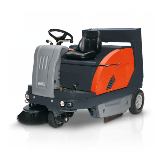
- Page 1 Instruction Manual Sweepmaster P1200 RH (6300.10) Sweepmaster D1200 RH (6300.20)
-
Page 2: Introduction
(see chapter "Safety Infor- volved. The applicable Accident Pre- mation”). vention Regulations and further Your authorised Hako dealer will be regulations in vigour concerning as- pleased to answer further questions re- pects of safety and working medicine garding the vehicle or the operation and will have to be complied with. -
Page 3: Notes On Warranty
Follow unpack- er considered valid in the event of mod- Hako dealer in accordance with the Bat- ing instructions on shipping pallet. Each ifications to the machine not authorized tery Law §... -
Page 4: Driving Licence
Introduction Any modification carried out at the Sweepmaster and having an influence on the type approval specifications and are not indicated there will render the type approval invalid. Before receiving a new type approval, the machine has to be presented to an authorized expert for issue of new expertise. -
Page 5: Table Of Contents
Acceptance of the machine . . 3 3.1.3 Steering ....21 Sweepmaster P1200 RH . . . 53 Disposing of the machine ..3 3.1.4 Filter System... -
Page 6: Safety Information
Safety information Safety information Safety and Warning Symbols All paragraphs in this manual referring to your personal safety, the safety of your machine and the environment pro- tection are attributed one of the follow- ing warning symbols: Symbol Hazardous for... Description Safety Provisions persons and goods... -
Page 7: General Provisions
• Usage of the machine in explosive • Persons being trained by qualified cerned, spare have to equal genuine areas is prohibited. Hako technicians only are autho- spare parts! • Pull the ignition key to avoid unau- rised to operate, service and repair thorized use of the machine. -
Page 8: Maintenance Instructions
Check the dirt hopper filling Hako service center. level frequently. • Observe the maintenance activities • Never let the engine run in indoor ar- •... - Page 9 • Pinching and shearing hazard by fit- • Switch off the engine and remove the frame. Only Hako-workshops are au- ting, removal and change of the bat- key before inspecting the machine or thorized to replace damaged parts.
-
Page 10: Specific Hazards
Safety information nance/service. valls. Immediately remedy defects such e.g. loose connections or Specific Hazards scorched cables. Safety equipment • Respect the operating instructions of • Do not operate the Sweepmaster the battery manufacturer. without safety equipment being in- • Never place metal objects or tools on stalled (all cover parts of the ma- batteries - short-circuit hazard! chine). -
Page 11: Information For Protection Of Environment
Environment ed to the normal waste. Provide for • For safe use of substances inheriting agreement with the Hako contract a danger to health and environment dealer on return and disposal ac- specific knowledge is required. -
Page 12: Labels At The Machine
Steam cleaner (Fig. 1/8) The following safety and information la- bels are legibly attached to the vehicle. Replace missing or illegible labels im- mediately. Hako nameplate front (Fig. 1/1) and rear (Fig. 2/1) Brake (Fig. 1/5) Inflation pressure (Fig. 1/9) 6 Bar Vehicle identification number (Fig. - Page 13 Safety information Sound power/Rise (Fig. 1/11) Pinching hazard (both sides) (Fig. 2/2) Rotating parts (Fig. 2/6) Sweepmaster P1200 RH Sweepmaster D1200 RH Fuel (Fig. 2/3) Sweepmaster P1200 RH Gasoline Hydraulic fluid (Fig. 2/7) Sweepmaster D1200 RH Diesel Adjust sweeping track side broom Burning surface (Fig.
- Page 14 Safety information Fig.1...
- Page 15 Safety information Fig.2...
-
Page 16: First Operation
4. Check engine oil level. the machine must be held by a qualified Do not use the Sweepmaster 5. Close seat hood. person sent by your local Hako contract at ambient temperatures of dealer. Your Hako dealer will be in- Start Machine more than 40°C. -
Page 17: Operation
First Operation Machine stopping and park- After work 6. Run the engine up and press slowly 1. Move the machine to suitable site for the choke knob (Sweepmaster cleaning. P1200 RH) down. 1. Release drive pedal which returns 2. Stop machine, lift sweeper roller and automatically in neutral position and Refer to LPG operating instruc- side boom. -
Page 18: Transport Rides And Towing
First Operation Transport rides and Towing Transport rides Before transporting the Sweepmaster on other vehicles, engage the parking brake and secure the machine by plac- ing wedges at the wheels and by straps on the tie-down points front (Fig. 3/1) and rear (both sides) (Fig. - Page 19 First Operation Towing If the Sweepmaster should be moved with engine being off, actuate the by- pass valve (Fig. 4/4) as follows. 1. Open seat hood. 2. Loosen wing screw left (Fig. 4/1) and wing screw right (Fig. 4/2) of side covers.
-
Page 20: Operation
Operation Operation Working Procedure General The Sweepmaster sweeper has been exlusively designed for collecting dry and moist matter from floor surfaces in e.g. factories, storage buildings, park- ing grounds and pedestrian areas. Functional Description The side broom (Fig. 5/1) is used to col- lect dirt at corners and borders and to enlarge the working width as well as to increase the area performance on large... -
Page 21: Sweeper Roller
3.1.3 Steering Steerage is effectuated mechanically from steering wheel to front wheel via chain. This chain is to be re-adjusted as required. Fig.6 Any work at the steering has to be executed by authorized Hako-service-workshop only. -
Page 22: Filter System
Operation 3.1.4 Filter System Dust Evacuation The filter system is located in the filter case (Fig. 7/1) above the dirt hopper (Fig. 7/2). The suction fan transports the fine dust raised by the sweeper roll- er to the plate filter (Fig. 7/3) where it is separated. -
Page 23: Brake
(Fig. 8/2) are located in front of the chassis, behind the front cover (Fig. 8/ Any work at the braking system has to be executed by autho- rized Hako-service-workshop only. 3.1.7 Travel Drive Assembly The Sweepmaster are equipped with a... -
Page 24: Operating Elements
Operation Operating Elements 1 Actuator for folding apron 2 Service brake lock 3 Service brake / parking brake pedal 4 Drive pedal, reverse 5 Drive pedal, forward 6 Control panel 7 Seat adjustment 8 Lever for dirt hopper (lifting-lowering-swinging) Fig.9... - Page 25 Operation Actuator for folding apron (Fig. 9/1) Drive pedal, reverse (Fig. 9/4) Lever for dirt hopper (Fig. 9/8) To open and close the folding apron for To change direction to reverse ride with (lifting-lowering-swinging) collecting coarse dirt during sweeping contineous regulation of riding speed at Lever for lifting-lowering-swinging the drive.
-
Page 26: Control Panel
14 Warning light (Option) 15 Rotating beacon (Option) 16 Side broom left (Option) 17 Control lamp, engine oil pressure 18 Choke flap knob Sweepmaster P1200 RH 19 Control lamp engine oil pressure and water temperature 20 Control lamp, preheat Sweepmaster D1200 RH... - Page 27 Operation Side broom lever (Fig. 10/2) To lift and lower the side broom or lower and turn on the side broom and sweep- Sweeper roller lever er roller in one process (Fig. 10/1). - Lower side broom = push lever. and lifted-up disposal (Fig.
- Page 28 Operation After jolting, the knob is to be kept in position 1 for about 25 seconds. Battery charge status indicator Control lamp, direction indicator (Fig. 10/9) (Option) ((Fig. 10/6) Lights upon actuation of the ignition Indicate, if using the indicator lever, the switch and has to extinguish as the en- Control lamp, shaking system direction.
- Page 29 Indicate changing of direction - Lever down = to left. - Lever up = to right. Control lamp, engine oil pressure (Sweepmaster P1200 RH only) (Fig. 10/17) Lights upon, if too few engine oil in the engine oil tank. Stop the machine and refill engine oil.
- Page 30 Control lamp engine oil pressure and water temperature (Sweepmaster D1200 RH only) (Fig. 10/19) The contrl lamp lights upon occurrence of an error at the engine or the control- ler. If control lamp continues lighting please inform the Hako Service depart- ment.
-
Page 31: Emtying Of The Dirt Hopper
Operation 3.2.2 Emtying of the Dirt Hopper Proceed to emtying of the dirt hopper as follows: • Lift and switch off side broom and sweeper roller. • Proceed to shaking of the filter sys- tem. • Lift dirt hopper as follows: Pull lever for dirt hopper (Fig. - Page 32 Operation • Lower dirt hopper as follows: ground before lifting the dirt Pull lever for dirt hopper (Fig. 11/1) hopper. down and simultaneously pull the le- ver for sweeper roller and release for When the dirt hopper is lifted, lifted-up disposal (Fig. 11/2) in arrow the operator has to ride the direction.
-
Page 33: Technical Data
Technical Data Technical Data Sweepmaster Dimensions and weights Length with side broom 1998 Width without side broom 1142 Width with 1 side broom 1142 Width with 2 side brooms 1142 Height above driver’s seat 1520 Dead weight V: 763 / D: 784 Admissible total weight 1330 Driving and sweeping performance... - Page 34 Technical Data Sweepmaster Filter system Filtering surface m² Plate filter peaces Sweeper roller Length / diameter 800 / 430 Wearing limit Speed 1/min 500+/-20 Sweeping track 70+10 Quantity of bristle rows 12 v-shaped Serial bristling Ground clearance of sealing Sealing strips, left / right / rear 1 / 1 / 4 Sealing strip, front lying on the bottom...
- Page 35 Technical Data Sweepmaster Dirt hopper Hopper capacity litre Drive wheels wheel front, solid rubber tyres 4.00-4 Wheels rear 4.00-8 Infaltion pressure Solid rubber tyres (rear) 4.00-8 (Option) Hydraulic system Travel drive assembly Haydraulic fluid, e.g. Mobiloil DTE 15 M (or an equivalent oil) Hydraulic tank, capacity litre Fluid filter cartridge...
- Page 36 Technical Data Sweepmaster P1200 RH D1200 RH Engine Manufacturer Briggs & Stratton Lombardini Type Vanguard V-Twin LDW 502 Working process/no. of cylinders 4-Takt / 2 Zyl. 4-Takt / 2 Zyl. Piston capacity cm³ Performance at 2550 rpm Service speed (with sweeper roller, side broom 2550+50 2550+50 and suction fan being on)
- Page 37 Technical Data P1200 RH D1200 RH Sweepmaster Noise emission value The sound pressure level (L pA ) (at the ear of the operator) measured according to DIN IEC dB (A) 60335-2-72 under nor-mal working conditions: Measurement inaccuracy (K pA ): dB (A) Sound power level (L WAd ) measured according to DIN EN 60335-2-72 under maximum working...
-
Page 38: Maintenance And Care
Please contact To be performed by the customer in ac- To be performed by qualified personnel your local Hako Service Centre or Hako cordance to the maintenance and care of authorised Hako Service Centre in contract dealer. We cannot be held lia-... -
Page 39: Maintenance Document
Maintenance and Care Maintenance document Handing over Hako-System-Maintenance I Hako-System-Maintenance II Hako-System-Maintenance III 50 operating hours 125 operating hours 250 operating hours Upgrade Workshop stamp Workshop stamp Workshop stamp Test drive Handing over to the customer Instruction carried out on:... -
Page 40: Maintenance Schedule
Maintenance and Care Maintenance Schedule Hako-System Mainten. Customer The following maintenance works are to be performeded by the customer. Interval Discription of task daily Check engine oil level and refill if required Check fuel level and refill if required Check dirt hopper (dustbin), and empty if required... - Page 41 Maintenance and Care Hako-System Maintenance Cus- tomer The following maintenance works are to be performeded by the customer. Interval Discription of task weekly Check engine air cleaner for soiling and clean if required (tap, do not use com- pressed air), replace air cleaner insert if required...
- Page 42 Maintenance and Care Hako-System Maintenance I The following maintenance works are to be performeded by authorized Hako Service-Centre. Interval Discription of task after 50 hours of operation (uniquely) Change engine oil and engine oil filter Clean fuel filter Check engine speed...
- Page 43 Service-Centre. Interval Discription of task every 125 hours of operation Change engine oil and engine oil filter (Sweepmaster P1200 RH) Change engine air cleaner Check spark plug, replace if required Check zero centering of the drive pump Check service/parking brake and re-adjust if required...
- Page 44 Service-Centre. Interval Discription of task every 250 hours of operation Perform maintenance works according to Hako-System Maintenance II Change engine oil and engine oil filter (Sweepmaster D1200 RH) Check idling and service speed Check battery Check tension of steering chain and adjust tension if required...
- Page 45 Interval Discription of task every 500 hours of operation Perform maintenance works according to Hako-System Maintenance II and III Change hydraulic fluid and filter Engine: adjust valve and change seal of valve cover Check fixing screws (brake, steering wheel and lifted up disposal) and tighten if...
-
Page 46: Mount/Dismount Sweeper Roll
Maintenance and Care Mount/Dismount Sweeper Roller The sweeper roller is accessible from the left side of the machine and is to be dismounted as follows: • Lower sweeper roller • Pull ignition key and protect by en- gaging parking brake. •... -
Page 47: Adjust Sweeping Track
Maintenance and Care Adjust Sweeping Track The sweeping track width is to be • Check sweeping track 70 mm with the Sweepmaster. An adjustment device allows adaption With one full turn of the knob, to different sweeping conditions. The The sweeping track width can be ad- the track widens or broadens sweeper roller has to be adjusted for justed at the star-shaped knob (Fig. -
Page 48: Sealing Strips For Broom Compartment
Maintenance and Care Sealing Strips for Replace Side Broom Broom Compartment The side broom is located at the front In order to assure good function of the right of the machine (standard version). sweeper, a perfect condition of the seal- Use the lever (chapter 3.2.1, Fig. -
Page 49: Dismount Plate Filter
Maintenance and Care Dismount Plate Filter Proceed as follows for dismounting of the plate filter: • Turn engine off and pull key. • Secure machine by engaging park- ing brake. • Open quick-release locks (Fig. 15/1) and remove cover (Fig. 15/2). •... -
Page 50: Basic Cleaning Of Plate Filter
Maintenance and Care Basic Cleaning of Plate Filter Hold the plate filter (Fig. 16/1) in vertical position and drop it drom a height aof approx. 1m to the even floor as repre- sented in (Fig. 16/). The soiled side of the plate fil- ter points to the bottom. -
Page 51: Engine
Use appropriate tools for main- tenance, service, setting etc. As far as aspect of safety are concerned, spare parts will have to be at least of the same quality as the genuine spare parts. Sweepmaster P1200 RH Sweepmaster D1200 RH Fig.17... -
Page 52: Change Engine Oil
For change engine oil proceed as fol- lows: • Turn engine off and pull key. Sweepmaster D1200 RH Sweepmaster P1200 RH • Secure machine by engaging park- ing brake. • Open seat hood. • Loosen wing screws of the front cov- er and tip the front cover outwards. -
Page 53: Change Engine Oil Filter Sweepmaster P1200 Rh
Maintenance and Care 5.10.3 Change Engine Oil Filter Sweepmaster P1200 RH Change the engine oil filter according to maintenance schedule. For change engine oil filter proceed as follows: • Turn engine off and pull key. • Secure machine by engaging park- ing brake. -
Page 54: Change Engine Oil Filter Sweepmaster D1200 Rh
Maintenance and Care 5.10.4 Change Engine Oil Filter Sweepmaster D1200 RH Change the engine oil filter according to maintenance schedule. For change engine oil filter proceed as follows: • Turn engine off and pull key. • Secure machine by engaging park- ing brake. -
Page 55: Air Cleaner
Maintenance and Care 5.10.5 Air Cleaner The air cleaner is located in the engine compartment. Clean the air filter weekly and change them after 125 hours of operation. A soiled filtering insert may lead to reduced performance and heavy smoking of the en- gine. -
Page 56: Hydraulic System
We recommend having all oth- er works at the hydraulic sys- tem done by a authorized Hako-service-workshop. 5.11.1 Check Hydraulic Fluid Level • Turn engine off and pull key. • Secure machine by engaging park- ing brake. -
Page 57: Refill Hydraulic Fluid
Maintenance and Care • Pull dipstick (Fig. 22/3) and check 5.11.3 Change Hydraulic Filter the hydraulic fluid level, refill if re- quired. Change the hydraulic filter according to maintenance schedule. 5.11.2 Refill Hydraulic Fluid For change hydraulic filter proceed as •... -
Page 58: Change Hydraulic Fluid
Maintenance and Care 5.11.4 Change Hydraulic Fluid Change the hydraulic fluid according to maintenance schedule. For change hydraulic fluid proceed as follows: • Move up the dirt hopper (Fig. 24/1). • Turn engine off and pull key. • Secure machine by engaging park- ing brake. -
Page 59: V-Belt Drive
Maintenance and Care 5.12 V-Belt Drive 1 Suction fan V-belt (75 Hz) 2 Tensioning roller for dynamo 3 V-belt pulley 4 Hydraulic pump V-belt 5 Belt guide 6 Hexagonal nut 7 V-belt for sweeper roller 8 Hydraulic pump belt pulley 9 Coupling roller for sweeper roller 10 V-belt for sweeper roller 11 Belt pulley for sweeper roller... -
Page 60: Electric System
Maintenance and Care 5.13 Electric System 1 Pre-fuse (F1=15A) 2 Supply unit control perm.(F2=5A) 9 10 3 Supply unit control con- 11 12 nected(F3=10A) 4 Horn, oil pressure, option side broom left(F4=10A) 5 Electric lighting (F5=15A), option 6 Electric lighting (F6=10A), option 7 Parking and rear light left (F7=5A), option 8 Parking and rear light right (F8=5A),... - Page 61 Maintenance and Care 19 Dim light or head lamps (K6), option 20 Flasher unit (K7), option 21 LPG Switchgear unit (A1), option 22 Heater plugs (F14) (only diesel) 23 Main fuse (F0=50A) (below the battery) Fig.27...
-
Page 62: Special Equipment And Spare Parts
Maintenance and Care 5.14 Special Equipment and Spare Parts Designation Description Order no. Protective roof For Sweepmaster 6304 Liquid petroleum gas system Liquid petroleum gas system (LPG) without change bottle 6303 Side broom system, left With deflector plate, without brush 6336 Rotating beacon For mounting on the protective roof... -
Page 63: Ec-Declaration Of Conformity
Hako GmbH For the relevant implementation of the Name of the person authorised for safety and health requirements men- Hako to compile the technical file: Hamburger Straße 209-239 tioned in the Directives, the following D-23843 Bad Oldesloe standard (s) and / or technical specifica- Ludger Lüttel... - Page 64 Spitzentechnik für eine saubere und schönere Umwelt Advanced Technology for a Cleaner, Better Environment · · Hako GmbH Hamburger Str. 209-239 D-23843 Bad Oldesloe · +49 4531 806-0 Fax +49 4531 806-338...
Need help?
Do you have a question about the Sweepmaster P1200 RH and is the answer not in the manual?
Questions and answers