Advertisement
Quick Links
Upgrade Kit AL811 and AL811H amplifier
Rev2 Aug 15, 2022
Information in this modification manual is copyright 2022 by W8JI and CTR Engineering. I understand people like to
share things, but please remember we have several weeks' labor composing this document. Please consider a
PayPal gift to
w8ji@w8ji.com
when using these instructions if you do your own kit.
Please be aware MFJ has made multiple changes in the AL811 series, not all of them are good. The following are
known problems as of this date:
1.) The Cooltron fan has about 1/3 necessary airflow for (4) 811tubes in normal SSB/CW use. If your amplifier has a
Cooltron fan, you must change it. We offer a fan kit.
2.) MFJ has changed output coax grounding in later amplifiers. The coax shield grounds to the input board. This
must be corrected or amplifier stability is compromised.
Thank you for purchasing this kit (and/or modification manual). These kits and this technical manual are intended
to help fellow Hams understand failures and reduce expensive damage. This technical instruction manual and kits
bring 811 series amplifiers up to latest revisions. With basic hand tools and soldering skills anyone should be able
to upgrade or service their own amplifier.
www.ctrengineeringinc.com
Please order via email links on
https://
/ameritron-811-811h-upgrade-
kits/
or email order query only to orders@ctrengineeringinc.com
This modification manual is also the result of feedback, questions, and suggestions by fellow Hams. More
suggestions are always welcome. The overriding philosophy is everything reasonably possible should be done to
prevent expensive or annoying damage, especially to expensive radios. An amplifier should work as well as
possible for the cost.
These kits come in two basic forms with one add-on:
(Power Supply rebuild) 811KS
1.) four better sized higher-voltage much longer-life 5000 hours 105c rated electrolytics
2.) four improved bleeder/equalizer resistors
3.) one large 6A grid meter protection diode
4.) four 499K 1% 1kV rated two-watt temperature stable meter multiplier resistors. (Note: from parts supplier
issues, we may substitute two 1M ohm resistors. The value is printed on the resistors.)
(Protection Kit) 811KP
1.) three application tested GDT tubes (one can be a spare, primary protection is at the sockets)
2.) one large 6A meter protection diode
3.) one 100k 2-watt resistor (standby noise)
4.) two 3.9V 5-watt Zener diodes (bias)
10-ohm 9-watt CCS 10kV rated fault resistor (arc limiting)
5.)
Add on part:
811R200K
200-ohm 25-watt non-inductive TO-220 case load resistor kit with hardware (reduce gain and add stability in 3
tube 811 models). This also can make the AL811H more compatible with 100W radios, reducing power overshoot
in rigs like the ICOM 7300.
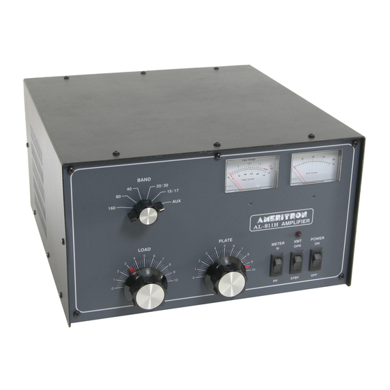
Overview
I designed the AL811 series many years ago. It was intended to be a minimal cost reasonable power level SSB and
CW only amplifier. The initial design request was for just two tubes, but that obviously would have been
inadequate. As a result, I added a third tube as a bare minimum cost amplifier, and pushed to have a better but
still not too expensive four-tube amplifier. The better version became the AL811H.
1
Advertisement

Related Manuals for AMERITRON AL811


Summary of Contents for AMERITRON AL811
- Page 1 Please be aware MFJ has made multiple changes in the AL811 series, not all of them are good. The following are known problems as of this date: 1.) The Cooltron fan has about 1/3 necessary airflow for (4) 811tubes in normal SSB/CW use. If your amplifier has a Cooltron fan, you must change it.
- Page 2 The three-tube 811 model is not neutralized. As with two unneutralized 572B tubes, three 811A tubes are marginally stable at upper HF. The AL811 should have a 200-ohm cathode swamping resistor, or even lower swamping resistance. Kit PN 811R200K has one chassis mount RF-rated 25W resistor, one 0.01uF coupling capacitor, and necessary hardware.
- Page 3 There have been dozens of instances of hard faults in tubes damaging radios. This has been blamed on many things by many people, including ALC voltage or relay line spikes. The actual damage to radio RF sections is from gas or debris arcs in tubes, or from tube anodes warped so badly by excessive heat the anode contacts the tube grid.
- Page 4 Zener diodes are used. The goal is to be around 10-20mA quiescent current per tube. This would be 30-60mA zero signal keyed idle current in the AL811, and 40-80mA idle in the AL811H...
- Page 5 This reduces the aggravation of protection diode failures Add a 100k resistor from filament to ground, or to a place I provided in later AL811’s that Ameritron for some reason never used. This prevents a weak “popping” noise in your receiver from intermittent gas tube ionization with some GDT’s and tubes...
- Page 6 GDT’s or to do most changes. GDTs in the AL811 three tube are installed as shown on the outermost tube: Figure 4 GDTs remove outer tube socket add lug(s) and GDT AL 811 only...
- Page 7 Figure 5 band switch shaft Remove the side rails on each side. (Fig 6) Remove the screws and pull the rear panel off the shaft. Do not damage or rotate the blue plastic input switch on the input circuit board. Once you have the panel back and off the shaft lay the panel down as in Fig. 6. You can now remove the shaft from the chassis.
- Page 8 Figure 7 properly wired back panel dropped Note: Incorrectly wired panels will not drop without unsoldering multiple transformer wires, and perhaps coax and other leads. It’s advisable to take a picture of the panel with wires attached to aid in reassembly of the panel.
- Page 9 After rear panel removal, remove any MOV’s. They will be located on the circuit board right down by the fan. MOV’s are sometimes blue. They will be present along with capacitors. Refer to Figs. 9, 10, & 11 to help identify MOV’s.
- Page 10 Figure 11 MOVs Remove MOV’s, do not remove capacitors. Generation I board: Figure 12 Generation I input board...
- Page 11 The Generation I board does NOT have the 24V bias point for the 100K resistor. In these amplifiers the 100K 2- watt resistor goes from anyplace on the filament system to chassis ground. Gen II board: Look for the small capacitor near dual relays (Fig. 13) and remove it, if installed. The string of 6 large forward connected rectifier diodes adds about 4 volts of bias.
- Page 12 Figure 14 Gen III and later input boards This is the ideal working position for all back panels. This is a correctly wired back panel. The back panel easily slips backwards off the switch drive without any wire removal. This is a two-relay board (the two black relays to the right side).
- Page 13 Figure 16 All units break or radius shaft rear edge Remove the tubes, the terminal strips, and lugs in these locations, and disconnect the two orange 1000 pF high-voltage blocking capacitors that go between the RF parasitic board and plate choke. Unsolder these capacitors at the end that solders to circuit board above the Plate Tune capacitor.
- Page 14 Flip the unit carefully on its side and remove the following screws: Figure 18 811H remove bottom screws Lay amplifier down and maneuver tube chassis to reach all sockets. Depending on wiring, the filament leads or red HV choke lead could require removal. The filament leads are supposed to be loosely twisted as in Fig 18. The optional 200-ohm 25-watt resistor requires drilling a #4 clearance hole, deburring the hole, and using heatsink compound and proper hardware (4-40 machine screw with lock washer and nut) to mount the resistor.
- Page 15 Remove the tubes before drilling. Be sure to not leave burrs. Supplied compound goes between the resistor and chassis. The AL811H does not need an isolation capacitor, the AL811 does need the supplied isolation capacitor. Figure 20 AL811H 200-ohm Pad...
- Page 16 Plate Choke Inspection Check all the solder connections carefully. Inspect the plate choke. If the plate choke has loose or overlapped wires it needs to be put back in a single tight wrap and “re-glued”. Q-dope can be made from a mix of lacquer thinner or Xylene and pure white Styrofoam “peanuts”...
- Page 17 Figure 24 Metering and power supply D16 can be mounted any physical way you like so long as the diode anode is at the center pad and the striped cathode end is toward the rectifier bank and filter capacitor bank negative. This diode allows the any arc energy to get from the chassis to the capacitor bank negative, harmlessly bypassing meters.
- Page 18 For easy soldering, pre-form D16 leads as shown. Also, pre-tin the leads with a generous amount of fresh solder: Figure 26 D16 form leads Zener Diode Bias There is no question that using as much positive cathode bias as possible, within limits of IMD, makes the tubes run cooler.
- Page 19 The Zener’s are safe to 1.3 amperes continuous duty when in open air. I suggest you use one Zener diode in addition to the six rectifiers used by Ameritron for a total of about 7.3 volts, or two Zener diodes in series if your amplifier does not have the bias rectifier string.
- Page 20 Figure 29 Zener's with 100k (avoid dropping back panel or early Gen I board) Warning: Ameritron has some transformers that are out-of-spec on the LV control winding. The LV control winding was specified to produce 12-14 Vdc output from a capacitor input filter system.
- Page 21 and can access these points, they are a slightly better point for the 100K resistor. This is NOT a mandatory point; it was just an intended production point when we were having problems with some early Chinese early 811 tubes. Figure 30 100K 2W resistor location A Early two-relay board with +24V point for resistor Figure 31 100K 2-watt resistor location B...
- Page 22 Figure 32 Zener location in fan airstream 811KP Surge Kit Glitch Resistor The large resistor in the surge kit is a special 10-ohm 10kV+ surge rated resistor. It replaces the small ferrite bead wound with wire. It adds an additional ten-ohms of surge resistance over the ~8 ohms of the RF plate choke and ~4 ohms of the filter capacitors.
- Page 23 Figure 33 remove bead choke Install the glitch resistor as shown below by surface soldering. Remember it replaces the ferrite bead HV choke. Figure 34 form resistor leads to surface solder See the supply kit below for resistor mounting, whether you have the supply kit or not. The 811KS supply kit that has solder-in 500V long life high temperature capacitors.
- Page 24 knee. They also add considerable margin to the voltage rating and reduce the time duration of surges. See kit 811KS below. Supply Rebuild Kit 811KS Filter Capacitors This kit provides new bleeders, meter protection diode, filter capacitors, and meter multipliers. All of the kit parts offer an improvement over factory parts.
- Page 25 Install new parts. Watch for shorts or accidental close contact. This is high voltage. Figure 36 install new PS parts Most parts need preformed or prepared lead lengths and bends. See the following suggestions: (Some kits use two 1M ohm, instead of four 499k. The 1M fit normally. The substitution is necessary because of supplier parts shortages.) Figure 37 Pre-form and pre-tin leads...
- Page 26 Pre-tinning leads aids soldering, but be careful pre-tinning through hole leads. Through hole leads may need hot-wiped of excess solder using a wet paper towel. (Note: Due to supplier parts shortages, we may substitute a different appearing resistor!) Figure 38 Cut and preform leads Cut leads to proper lengths.
- Page 27 Figure 19 add GDTs AL811H only (811 was in fig 4) ..............14 Figure 20 AL811H 200-ohm Pad ....................15 Figure 21 AL811 200-ohm swamping resistor and capacitor ............. 15 Figure 22 reglue choke all units ....................16 Figure 23 Replace sand color bleeders. Replace diode..............16 Figure 24 Metering and power supply ..................
Need help?
Do you have a question about the AL811 and is the answer not in the manual?
Questions and answers