Table of Contents
Advertisement
Quick Links
Advertisement
Table of Contents

Related Manuals for Cotek SE350 series


Summary of Contents for Cotek SE350 series
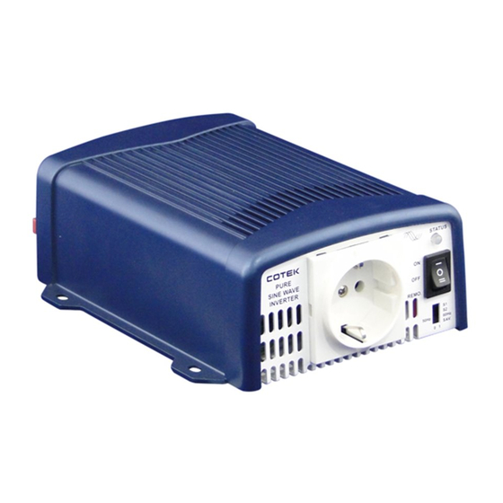
- Page 1 SE350 Series Pure Sine Wave Inverter User's Manual WWW.COTEK.COM.TW...
-
Page 2: Table Of Contents
Making DC Wiring Connections……...………………………………. AC Safety Grounding………………………………………………….. Inverter Operation……………………………………………………... 4. Troubleshooting guide………………………………………………………. 5. Maintenance………………………………………………………………….… 6. Warranty…………………………..………………………………………….… Copyright :This manual is the copyright of COTEK Electronic lnd. Co., Ltd. Be not allowed to reproduc or copy without permission of the owner. -
Page 3: Important Safety Information
1. Important Safety Information WARNING! Before installing and using the Inverter, you need to read the following safety information carefully. 1-1. General Safety Precautions 1-1-1. Do not expose the Inverter to rain, snow, spray, bilge or dust. To reduce risk of hazard, do not cover or obstruct the ventilation openings. -
Page 4: Features
2. Features Pure sine wave output (THD < 3%@ linear load) Output frequency:50 / 60Hz switch selectable Output voltage / power saving mode selectable Low power saving mode < 1W Input & output completely isolated design High efficiency Capable of driving inductive & capacitive loads at the start moment. A LED Indicator with twin color displays all operation status. -
Page 5: Electrical Performance
2-1. Electrical Performance MODEL SE350-112 SE350-124 SE350-148 SE350-212 SE350-224 SE350-248 Output Voltage 100 / 110 / 115 / 120 Vac ± 5% 200 / 220 / 230 / 240 Vac ± 5% Rated Power 350W Surge Power 700W Waveform Pure sine wave ( THD<3% @ rated VDC, linear load ) Frequency 50 / 60 Hz ±... -
Page 6: Mechanical Drawing
SE350 de-rating curve: 2-2. M echanical Drawing of Socket 127 [5.00] 150 [5.91]... -
Page 7: Instructions
3. Instructions This power inverter series is a the member of the most advanced line of mobile AC power systems available. To get the most out of the power inverter, it must be installed and used properly. Please read the instructions in this manual before installation and operation this model. - Page 8 3-1-2.Power Saving, AC Frequency& Output Voltage: Selected by Dip Switch Power Saving Dip Switch Frequency Dip Switch 50Hz 60Hz Output Voltage...
- Page 9 3-1-3. Status:Display Power & Fault Status Status LED Signal Power on Normal Saving mode O/P over load (100%~115%) O/P short circuit Over temperature Shut down high battery High battery Low battery Shut down low battery *Note: LED Status G=Green R=Red O=Orange Power on :Beep twice , LED shows green ->...
-
Page 10: Rear Panel Operation
3-2. Rear Panel Operation: 3-2-1. Before installing the inverter, make sure the main switch must be “OFF”. 3-2-2. Before using the remote unit, make sure the main switch must be “ REMOTE”. 3-2-3. Ensure the remote control contact is off. 3-2-4. - Page 11 BAT+ BAT- MODE III ON→INV - ON OFF INV - OFF → MODE IV EXT PWR RJ-11 Remote port for CR-8 (Remote controller) *NOTE: Only one of control mode can be presented. When operating. 3-2-6. DC Input Terminals: Connect to 12V / 24V / 48V battery or the other power sources. is positive, is negative.Reverse polarity connection 【...
-
Page 12: Protections Features
3-3. Protections Features: DC Input (VDC) Over Temperature Protection Over Voltage Under Voltage INTERIOR Under Model Voltage Shut- Shut- Restar Restar Shut-down Restar Alarm down down 15.5± 14.5± 10.5± 10±0.25V 12±0.25V 0.25V 0.25V 0.25V 31±0.5V 29±0.5V 21±0.5V 20±0.5V 24±0.5V 83±5℃ 53±5℃... -
Page 13: Making Dc Wiring Connections
3-4-6. Close to batteries – Avoid excessive cable lengths but do not install the Inverter in the same compartment as batteries. Use the recommended wire lengths and sizes (see section 3-5). Also do not mount the Inverter where it will be exposed to the gases produced by the battery. -
Page 14: Ac Safety Grounding
3-6. AC Safety Grounding: The AC output ground wire should go to the grounding point for your loads ( for example, a distribution panel ground bus ). 3-6-1. Neutral Grounding (GFCI'S): 3-6-1-1. 110V models:The neutral conductor of the AC output circuit of the Inverter is automatically connected to the safety ground during inverter operation. -
Page 15: Inverter Operation
UL standards requires us to test and recommend specific GFCI. Cotek has tested the following GFCI – protected 20A receptacles and found that they functioned properly when connected to the output of the Inverter. -
Page 16: Troubleshooting Guide
4. Troubleshooting guide: WARNING! Do not open or disassemble the Inverter. Attempting to service the unit yourself may result in a risk of electrical shock or fire. Problems and Symptoms Possible Cause Solutions “No AC Power Output” STATUS illuminates the red LED Over input voltage. -
Page 17: Maintenance
5. Maintenance: Very little maintenance is required to keep your inverter operating properly. You should clean the exterior of the unit periodically with a damp cloth to prevent accumulation of dust and dirt. At the same time, tighten the screws on the DC input terminals. 6. - Page 18 No. 33, Sec. 2, Renhe Rd., Daxi Dist., Taoyuan City 33548, Taiwan Phone:+886-3-3891999 FAX:+886-3-3802333 E-mail:sales@cotek.com.tw http:// www.cotek.com.tw 2015-12-A3...
Need help?
Do you have a question about the SE350 series and is the answer not in the manual?
Questions and answers