Table of Contents
Advertisement
Advertisement
Table of Contents

Subscribe to Our Youtube Channel
Related Manuals for Cotek SD2500-112


Summary of Contents for Cotek SD2500-112
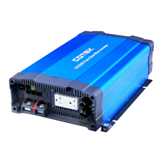
- Page 1 SD Series Pure Sine Wave Power Inverter User’s Manual...
-
Page 2: Table Of Contents
Table of Content 1. Important Safety Information ........... 1 1-1. General Safety Precautions 1-2. Precautions When Working with Batteries 1-3. Installation 2. Functional Characteristics ............2 2-1. General Information 2-2. Application 2-3. Electrical Performance 2-4. Mechanical Drawings 3. Introduction ................9 3-1. - Page 3 3-16. RS-232 Port 3-17. Fan Ventilation 3-18. Protections Features 4. DC Wiring Connections ............16 4-1. DC Input Terminals 4-2. Hard-wire Installation 5. Parallel Mode ................22 5-1. Prepare for Parallel Usage 5-2. Wiring for Parallel Usage 5-3. Industry Applications 6.
-
Page 4: Important Safety Information
1. Important Safety Information WARNING! Before using the Inverter, read and save the safety instructions. 1-1. General Safety Precautions 1-1-1 Do not expose the Inverter to rain, snow, spray, bilge or dust. To reduce risk of hazard, do not cover or obstruct the ventilation openings. -
Page 5: Installation
1-3. Installation The power inverter should be installed in a location that meets the following requirements: Dry – Do not allow water to drip or splash on the inverter. 1-3-1 Cool – Ambient air temperature should be between -20℃ and 50℃, 1-3-2 but he cooler the better. -
Page 6: Application
Features Parallel redundancy design for power expansion Multiple industrial applications that create 1Ф3ω / 3Ф4ω power systems User-friendly remote control Automatic master mechanism to eliminate single point failure and optimize reliability Built-in ATS and AC circuit breaker ... -
Page 7: Electrical Performance
2-3. Electrical Performance MODEL SD2500-112 SD2500-124 SD2500-148 SD2500-212 SD2500-224 SD2500-248 Output 2500W Rating Power (de-rating after 40°C, refer to de-rating curve) Peak Power 3000W (3Sec.) Surge Power 4000W (<0.2Sec.) Pure Sine Wave Waveform Efficiency (Max.) Output 100 / 110 / 115 / 120VAC ±3% 200 / 220 / 230 / 240VAC ±3%... - Page 8 MODEL SD2500-112 SD2500-124 SD2500-148 SD2500-212 SD2500-224 SD2500-248 Protection BAT.Low 10.5VDC 21.0VDC 42.0VDC 10.5VDC 21.0VDC 42.0VDC Alarm BAT.Low 10.0VDC 20.0VDC 40.0VDC 10.0VDC 20.0VDC 40.0VDC Shut-down BAT.Low 12.5VDC 25.0VDC 50.0VDC 12.5VDC 25.0VDC 50.0VDC Restart BAT.High 15.5VDC 31.0VDC 62.0VDC 15.5VDC 31.0VDC 62.0VDC Alarm BAT.High...
- Page 9 MODEL SD3500-112 SD3500-124 SD3500-148 SD3500-212 SD3500-224 SD3500-248 Output 3500W (de-rating after 35°C, refer to de-rating curve for 12V) Rating Power (de-rating after 40°C, refer to de-rating curve for 24V and 48V) Peak Power 4500W (3Sec.) Surge Power 6000W (<0.2Sec.) Pure Sine Wave Waveform Efficiency (Max.)
- Page 10 MODEL SD3500-112 SD3500-124 SD3500-148 SD3500-212 SD3500-224 SD3500-248 Protection BAT.Low 10.5VDC 21.0VDC 42.0VDC 10.5VDC 21.0VDC 42.0VDC Alarm BAT.Low 10.0VDC 20.0VDC 40.0VDC 10.0VDC 20.0VDC 40.0VDC Shut-down BAT.Low 12.5VDC 25.0VDC 50.0VDC 12.5VDC 25.0VDC 50.0VDC Restart BAT.High 15.5VDC 31.0VDC 62.0VDC 15.5VDC 31.0VDC 62.0VDC Alarm BAT.High 16.0VDC 32.0VDC...
-
Page 11: Mechanical Drawings
De-rating Curve SD 2500 SD 3500 2-4. Mechanical Drawings Unit:mm [inch]... -
Page 12: Introduction
3. Introduction Front Panel Rear Panel Front Panel/Rear Panel Power ON/OFF/REMOTE (Main) AC output socket switch Status LED Reset Button CAN2 Port (only to be used in parallel Dip Switch (S1~S8) mode) CAN1 Port (only to be used in parallel DC Input - mode) LCM Port (Connection for LCD remote... -
Page 13: Led Indicator 1
3-2. LED Indicator Green LED LED Signal Status Solid Power OK Slow Blink Power Saving Orange LED LED Signal Status Fast Blink Slow Blink Red LED LED Signal Status Intermittent Blink Fast Blink OVP- Shut-down Slow Blink UVP- Shut-down Slow Blink Intermittent Blink Fan Failure 3-3. - Page 14 3-3-1 DIP switch Set-up S1 S2 S3 S4 S5 S6 S7 S8 Scenario AC output voltage : 100VAC/200VAC AC output voltage : 110VAC/220VAC AC output voltage : 115VAC/230VAC AC output voltage : 120VAC/240VAC AC output frequency : 50Hz AC output frequency : 60Hz Power saving mode setting (S4~S6);...
-
Page 15: Dc Input - 1
3-3-3 S4~S6 Set-up for 3 Phase output S1 S2 S3 S4 S5 S6 S7 S8 Scenario Master (0°); "R" Phase to be used for 1Ø 3W output in series connection(Master) or 3Ø 4W output connection("R" Phase) Slave (0°) with current sharing to be used in parallel connection only Slave (0°), to be used for 1Ø... -
Page 16: Chassis Ground: Connect The Wire # 8 Awg To Vehicle Chassis
3-6. Chassis Ground: Connect the wire # 8 AWG to vehicle chassis. WARNING! Operating the inverter without a proper ground connection may cause electrical safety hazard. 3-7. AC Output : (Please refer to Hard wiring connections on p. 19) 3-8. By-pass AC input: (please refer to Hard wiring connections on p. -
Page 17: Lcm Port
3-14. LCM Port: Connection for LCD remote control panel, can you set and display the SD-series operation status. LCD Remote Control Panel SD-series PIN Num. Signal Description PIN Num. CANH CANL VCC- VCC+ 5VS- 5VS+ The cables should be as short as possible (less than 32.8 feet / 10 meters) so that they can handle the signal. -
Page 18: Rs-232 Port
3-15-1 Parallel Jump Function (please refer to section 3-6 for further detailed info.) 1. Before installing the inverter, you need to ensure the main switch is in the OFF position. 2. Use 20 ~ 24 #AWG wire to connect the parallel jump terminal. 3-15-2 Remote Control Function 1. -
Page 19: Fan Ventilation 1
SD-series Computer PIN Num. Signal Description Signal Description PIN Num. Not used Not used Not used Not used Not used Not used The connection between this SD-series and the computer is as follows: 3-17. Fan Ventilation The rear panel must keep the distance at least 1 inch from any surrounding items. - Page 20 The following are recommended cable diameter for the best performance of the inverter. (Applies to both 120V and 230V versions) Model No Wire AWG Inline Fuse SD2500-112 / 212 # 3/0 350 A SD2500-124 / 224 175 A SD2500-148 / 248...
-
Page 21: Dc Input Terminals 1
Do not place anything between battery cable lug and terminal surface. Assemble exactly as shown. Fig. 1: Battery to inverter connection WARNING! During the first installation, it is normal to experience a small spark is a normal phenomenon because the internal capacitors charging. -
Page 22: Hard-Wire Installation 1
DC Input Voltage Model Minimum Maximum 4-2. Hard-wire Installation: 4-2-1 SD series provides the flexibility of hard-wire connection, and this function will make external control panel wiring easier. Step 1. > Remove the four screws of AC wiring compartment and pull it out with care. - Page 23 100VAC~120VAC / 200VAC~240VAC System NOTE: The only difference between 110V and 220V is within the AC Input breaker L or N and thus will not affect the wiring configuration. 4-2-2 Connect AC output and AC input wiring to the SD series terminals. Please take the following information as your reference.
- Page 24 the “N” terminal of the AC input source. If the AC input source is the power supplied from the utility, the “N” terminal would be a Neutral in the true sense. It will normally be bonded to the earth ground and will read almost 0 V with respect to the earth ground.
-
Page 25: Parallel Mode
5. Parallel Mode 5-1. Prepare for Parallel Usage 1. Before setting, you need to ensure that the main switch is”OFF”. 2. Before using the parallel function, you need to set the parallel jump of the green terminal the status of which must be “ON”, if the between in another SD is set to ”OFF”... -
Page 26: Wiring For Parallel Usage 2
Parallel Unit 1 Unit 2 Unit 3 Parallel Jump OFF* * If you parallel N units, the first (unit 1) and the last unit (unit N) must set parallel jumper in ON position. NOTE: SD series can be used for N+1 (N≦14) redundancy and the ability of enlarge the capacity (Users can install maximum 15 units of inverters together in parallel in order to provide the power expansion). - Page 27 Not prefer to use different battery-bank attery- attery- configuration because batteries voltage is bank 1 bank 2 difficult to control.
-
Page 28: Industry Applications 2
5-2-3 Remove Parallel Connection 1. If “A” and “B” was used in parallel, we only need to operate one of them. 2. In the parallel mode, the first SD turned on will be the master. 3 . If we just want to use only one of SDs, we can just remove RJ45 cable, but make sure the operation is performed in shut-down mode. -
Page 29: Rs-232 Command
1Φ3ω 3Φ4ω Type Set up 3Φ4ω do not support N+1 1Φ3ω do not support N+1 operation, maximum of three SD operation, maximum of two SD inverters, THD < 4% Warning inverters, THD < 4% **DIP switch (S7) must be set to “1”... - Page 30 This unit uses high-level language commands with a CR (0DH) and LF (0AH) as the end of the command. The system would interpret and execute the command only after these two characters are received. After the unit execute the command, it would send a response string to the computer.
-
Page 31: Troubleshooting
We guarantee this product against defects in materials and workmanship for a period of 24 months from the date of purchase. Please contact with your local COTEK authorized distributor for RMA (Return material Authorization) service. Please note that COTEK will ensure our products are operational before delivery and the warranty service is offered to the unit which has defect caused under normal use, in the judgment of COTEK’s... - Page 32 No. 33, Rong Hsin Rd., Bade City, Taoyuan County, Taiwan Phone:886-3-3661581 FAX:886-3-3676029 http:// www.cotek.com.tw 2013.06._A0...
Need help?
Do you have a question about the SD2500-112 and is the answer not in the manual?
Questions and answers