Table of Contents
Advertisement
Advertisement
Table of Contents

Related Manuals for Cotek S1500-112


Summary of Contents for Cotek S1500-112
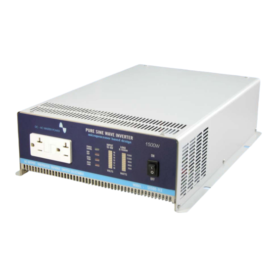
- Page 1 S1500 Series Pure Sine Wave Inverter User’s Manual...
-
Page 2: Table Of Contents
Interface command …………………………..…………….………….. 22~25 Appendices C Remote control operations…………………….………………………. 26~27 Power saving mode…………………………..………………………… 28~31 ©Copyright : This manual is the copyright of COTEK Electronic Ind. Co., Ltd. And may not be reproduced or copied without the express permission of the owner. - Page 3 (e13 020932) declaration of conformity……………………. 35 10-5 UL (UL458) declaration of conformity………….……………………. 36 ©Copyright : This manual is the copyright of COTEK Electronic Ind. Co., Ltd. And may not be reproduced or copied without the express permission of the owner.
-
Page 4: General Safety Precautions
1. Important Safety Instructions WARNING ! Before you install and use your S1500 Inverter, be to read and save these safety instructions. 1-1. General Safety Precautions 1-1-1. Do not expose the S1500 Inverter to rain, snow, spray, bilge or dust. To reduce risk of hazard, do not cover or obstruct the ventilation openings. -
Page 5: Features
2. Features Pure sine wave output (THD < 3%) Output frequency:50 / 60Hz switch selectable Low power “ Power Saving Mode “ to conserve energy RS – 232C interface / remote controls port Built–in voltage and watt meter Thermostatically controlled cooling fan Advanced microprocessor Protection:Input low voltage Overload... -
Page 6: Electrical Performance
2-2. Electrical Performance Specification Model No. Item S1500-112 S1500-124 S1500-148 S1500-212 S1500-224 S1500-248 Continuous Output Power 1500W Surge Rating 2000W Input Voltage Output Voltage 100 / 110 / 115 / 120V ± 3% 200 / 220 / 230 / 240V ± 3% Frequency 50/60Hz +/- 0.05%... -
Page 7: Mechanical Drawings
2-3. Mechanical Drawings... -
Page 8: Introduction
3. Introduction: This power inverter series is a the member of the most advanced line of mobile AC power systems available. To get the most out of the power inverter, it must be installed and used properly. Please read the instructions in this manual before installing and using this model. 3-1. -
Page 9: Rear Panel Operations
3-1-4. AC outlet (Outlet sockets available): North America (GFCI) North America Continental European (SCHUKO) Australia / New Zealand Universal United Kingdom 3-2. Rear Panel Operation :... - Page 10 3-2-1. Ventilation openings: Do not obstruct, allow at least 3 inch for air flow. 3-2-2. Battery terminals: Connect to 12V / 24V / 48V battery or other 12V / 24V / 48V power source. 【+】is positive,【-】is negative. Reverse polarity connection will blow internal fuse and may damage inverter permanently.
-
Page 11: Installation
3-3. Installation: Where to install. The power inverter should be installed in a location that meets the following requirements: 3-3-1. Dry – Do not allow water to drip or splash on the inverter. 3-3-2. Cool – Ambient air temperature should be between 0℃ and 40℃, the cooler the better. - Page 12 WARNING! You may observe a spark when you make this connection since current may flow to charge capacitors in the power inverter. Do not make this connection in the presence of Flammable fumes. Explosion or fire may result. WARNING! Make sure all the DC connections are tight (torque to 9-10 ft-lbs, 11.7-13Nm).
-
Page 13: Ac Safety Grounding
3-4-6. Set power inverter switch to the OFF position, the indicator lights may blink and the internal alarm may sound momentarily. The is normal. Plug the test load into the AC receptacle on the front panel of the inverter. Leave the test load switch off. 3-4-7. -
Page 14: Making Dc Wiring Connections
S1500 Inverter is equivalent to the waveform provided by utilities, compliance with UL standards requires us to test and recommend specific GFCI. Cotek has tested the following GFCI-protected 20A receptacles And found that they functioned properly when connected to the output of the S1500 Inverter. - Page 15 Increasing your DC cable size will help improve the situation. Cotek recommends the following cables for optimum inverter performance (apply both 120V and 230V versions ) Model No...
-
Page 16: Inverter Operation
This will ensure that the power inverter does not have to deliver the starting currents for all the loads at once. 3-7-1. Indicators : Input power range as follows: Model voltage Min. voltage Max. voltage S1500-112 10.5 15.0 S1500-212 S1500-124 21.0 30.0... - Page 17 3-7-2. Battery voltage indicator: The battery voltage bar graph indicates the voltage at the input terminals of the power inverter. At low input current, this voltage is very close to the battery voltage. At high input current, this voltage will be lower than the battery voltage because of the voltage drop across the cable and connections.
-
Page 18: Power Output
3-9. Protections Features: Dc Input Over Dc Input under Over temperature voltage voltage protection Dc Input under Model voltage alarm Shut-down Restart Shut-down Restart Shut-down Restart S1500-112 16.7VDC 15.2VDC 10.2VDC 9.5VDC 12.6VDC S1500-212 S1500-124 ℃ ℃ 33.4VDC 30.4VDC 20.4VDC 19.0VDC 25.2VDC... -
Page 19: Troubleshooting Guide
4. Troubleshooting guide: WARNING Do not open or disassemble the S1500 Inverter. Attempting to service the unit yourself may result in a risk of electrical shock or fire. Common problems -television interference: Operation of the power inverter can interfere with television reception on some channels. -
Page 20: Maintenance
No output voltage. Thermal shutdown Improve ventilation, Over Temp indicator Make sure ventilation on, load less than openings in inverter 1500W. are not obstructed. Reduce ambient temperature. No output voltage, Short circuit or Wiring Check AC wiring Over Load indicator error. -
Page 21: Appendices A
7. Appendices A 7-1. Dip Switch (110V) VOUT FREQ. BAUD (VAC) (Hz) RATE 1200 2400 ---- ---- 4800 ---- ---- 4800 7-2. Dip Switch (220V) VOUT FREQ. BAUD (VAC) (Hz) RATE 1200 2400 ---- ---- 4800 ---- ---- 4800 S4 is unavailable ※... -
Page 22: Appendices B
8. Appendices B 8-1. Operations of RS232 Serial Port 8-1-1. Hardware design: This unit uses a 9-pin D connector and three of RS232 signal lines: RECEIVE DATA (RXD): PIN2 TRANSMIT DATA (TXD): PIN3 DATA TERMINAL READY (DTR): PIN4 8-1-2. The connection between this unit and a computer is as follows: Computer Power inverter 8-1-3. -
Page 23: Interface Command
8-2. Interface Command : The buffer size used for the RS232 port is 12-bytes. This unit will ignore all bytes more than this value. During transmission, this unit (inverter) will indicate it is ready to receive data from computer by the DTR line. A computer has to check the DTR line before sending any information to this unit. - Page 24 8-2-2-2. Command format This unit supports the following commands. There should always be a CR (0DH) and a LF (0AH) appended to the command while sending the command to this unit. 8-2-2-3. PWRS command: Power saving function control Format: PWRS < value > Illustration: A space (ASCII code 20H) is needed between PWRS and <...
- Page 25 8-2-2-5. To query status command Format: STUS ? Illustration: Don’t need to add any of parameter. To respond the result be hexadecimal code replaced by 2 ASCII codes that is between 00 ~ FF (0~255), then convert the Hex code to the binary digit after obtaining 8 bytes digit that can be one of following: “B2 ”...
- Page 26 8-2-2-7. To query load level command: Format: Load ? Illustration: Don’t need adding any of parameter. Respond: The same as BATT ? <value> can be one of following Decade Indication code code Load < 5%, All of LED indicators go “OFF” Load <15%, LED 1 indicator glows.
-
Page 27: Appendices C
9. Appendices C 9-1. Remote Control Option : System Configuration 9-1-1. Plug the 9-pin D-SUB connector of the remote controller in the RS-232 port of the Inverter. 9-1-2. Check the setting of DIP-SW S5 & S6, The communication BAUD RATE should be set to 4800bps (S5 & S6 OFF). :... - Page 28 : Operations 9-1-4. Set SLIDE SW “ON”(Keypads will not work if SLIDE SW is set “OFF”) 。 9-1-5. Remote ON /OFF: Pressing a button (and releasing in one second) will change (toggle) the output ON/OFF mode and the display of LEDS will be changed accordingly. 9-1-6.
-
Page 29: Power Saving Mode
9-2. Power saving mode MICROPROCESSOR BASED SINE WAVE INVERTER S-1500 SERIES ENABLING AND DISABLING POWER SAVING MODE 9-2-1. When an inverter is powered on and is running in idle condition ( there is no load or the load connected to the inverter has been switched off ), it will still draw some power from the batteries for keeping the system alive 9-2-2. - Page 30 9-2-4. Power saving “sleep ” mode, enabled 9-2-4-1. The front plate has a green led marked “ power saving ” for indication of enabled state of power saving “sleep” mode ( here-in-after referred to as the green led ) 9-2-4-2. The power saving “sleep ” mode is enabled in either Of the following indications ( when inverter is in on condition ) : The green led flashing sequence is :...
- Page 31 9-2-5-2. If now a load more than 2 to 15 watts is switched on, the green led stops flashing after about 3 seconds and will be lighted continuously. After about 15 to 18 seconds after the green led has stopped flashing and become steady, output power will be available to the load.
- Page 32 9-2-7. Switching between enabled and disabled states of power saving “sleep mode 9-2-7-1. Switching between enabled and disabled states of power saving “sleep” mode can be done with the help of the power on / off switch on the front plate of the inverter or with the help of the optional remote control.
-
Page 33: Fcc (Class B) Declaration Of Conformity
10-1. FCC (Class B ) Declaration of Conformity... -
Page 34: Ce (Emc En55022B) Declaration Of Conformity
10-2. CE (EMC EN55022B) Declaration of Conformity... -
Page 35: Ce (Lvd En60950) Declaration Of Conformity
10-3. CE (LVD EN60950) Declaration of Conformity... -
Page 36: E-Mark (E13 020932) Declaration Of Conformity
10-4. e-mark (e13 020932) Declaration of Conformity... -
Page 37: Ul (Ul458) Declaration Of Conformity
10-5. UL (UL458) Declaration of Conformity... - Page 38 No. 33, Rong Shin Rd., Pa Te City, Tao Yuan County, Taiwan Phone: 886-3-3661581 FAX: 886-3-3676029 E-mail: Sales@cotek.com.tw http: // www.cotek.com.tw 2004.2...
Need help?
Do you have a question about the S1500-112 and is the answer not in the manual?
Questions and answers