Table of Contents
Advertisement
Advertisement
Table of Contents

Subscribe to Our Youtube Channel
Related Manuals for Cotek ST Series


Summary of Contents for Cotek ST Series
- Page 1 ST Series Pure Sine Wave Power Inverter User’s Manual...
-
Page 2: Table Of Contents
Contents 1. Important Safety Instructions……………………………………………………………………. 2 1-1 General safety precautions…………………………………………………………………… 2 1-2 Precautions when working with Batteries…………………………………………………… 2 2. Functional Characteristics.………………………………………………………………………. 3 General Information…………………………………………………………………………. 3 Application……………………………………………………………………………………. 3 Features………………………………………………………………………………………. 3 Electrical Performance………………………………………………………………………. 5 Mechanical drawings………………………………………………………………………... 6 3. Installation…………………………………………………………………………………………… 7 Where to install………………………………………………………………………………. 7 Hard-wire Installation………………………………………………………………………... -
Page 3: Important Safety Instructions
1. Important Safety Instructions WARNING ! Before using the Inverter, read and save the safety instructions. 1-1. General Safety Precautions 1-1-1. Do not expose the Inverter to rain, snow, spray, bilge or dust. To reduce risk of hazard, do not cover or obstruct the ventilation openings. -
Page 4: Functional Characteristics
2. Functional Characteristics 2-1. General Information ST-series completes with stand –alone power inverter with AC transfer switch and is suitable for RV, Marin and Emergency appliances. When utility AC power cutoff, the transfer relay is de-energized and the load is automatically transferred to the Inverter output. Once the AC utility is restored, the relay is energized and the load is automatically reconnected to AC utility. - Page 5 2-3-4. Speed up transfer time and synchronized operation with the AC source at all times that allows the transfer to be interruption-free for sensitive equipments. 2-3-5. Built in advance microprocessor to make friendly interface with user. 2-3-6. Low power “ Power Saving Mode “ to conserve energy 2-3-7.
-
Page 6: Electrical Performance
2-4. Electrical Performance Specification Model No. Item ST1000-112 ST1000-124 ST1000-148 ST1000-212 ST1000-224 ST1000-248 Continuous Output Power 1000W Maximum Output Power (3Min.) 1150W Surge Rating 2000W Input Voltage Output Voltage 100 / 110 / 120V ± 3% 220 / 230 / 240V ± 3% Frequency 50 / 60Hz +/- 0.05% (Switch Selectable) - Page 7 2-4. Electrical Performance Specification Model No. Item ST1500-112 ST1500-124 ST1500-148 ST1500-212 ST1500-224 ST1500-248 Continuous Output Power 1500W Maximum Output Power (3Min.) 1725W Surge Rating 3000W Input Voltage Output Voltage 100 / 110 / 120V ± 3% 220 / 230 / 240V ± 3% Frequency 50 / 60Hz +/- 0.05% (Switch Selectable)
- Page 8 2-4. Electrical Performance Specification Model No. Item ST2000-112 ST2000-124 ST2000-148 ST2000-212 ST2000-224 ST2000-248 Continuous Output Power 2000W Maximum Output Power (3Min.) 2300W Surge Rating 4000W Input Voltage Output Voltage 100 / 110 / 120V ± 3% 220 / 230 / 240V ± 3% Frequency 50 / 60Hz +/- 0.05% (Switch Selectable)
- Page 9 2-4. Electrical Performance Specification Model No. Item ST2500-112 ST2500-124 ST2500-148 ST2500-212 ST2500-224 ST2500-248 Continuous Output Power 2500W Maximum Output Power (3Min.) 2875W Surge Rating 5000W Input Voltage Output Voltage 100 / 110 / 120V ± 3% 220 / 230 / 240V ± 3% Frequency 50 / 60Hz +/- 0.05% (Switch Selectable)
-
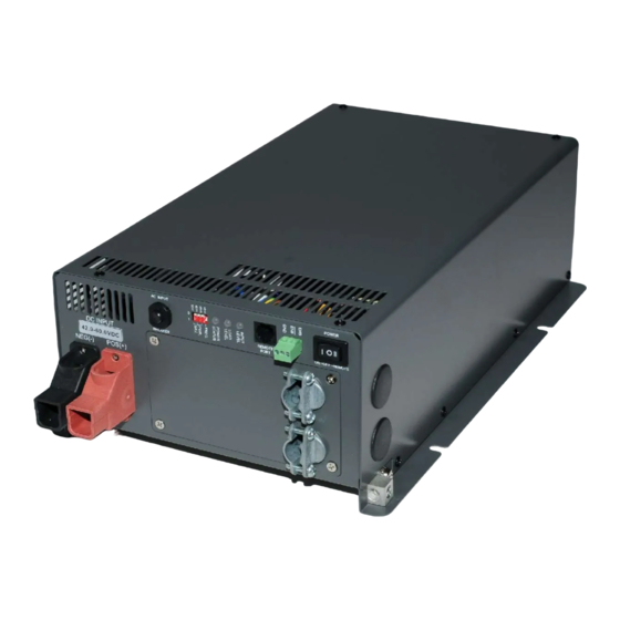
Page 10: Mechanical Drawings
2-5. Mechanical drawings AC INPUT POWER POWER STATUS INPUT LEVEL LOAD LEVEL REMOTE BREAKER ON-OFF-REMOTE PORT DC INPUT NEG(-) POS(+) REVERSE POLARITY WILL DAMAGE UNIT... - Page 11 2-5. Mechanical drawings AC INPUT POWER POWER STATUS INPUT LEVEL LOAD WARNING: LEVEL REVERSE POLARITY WILL DAMAGE UNIT REMOTE BREAKER ON-OFF-REMOTE PORT DC INPUT POS(+) NEG(-)
-
Page 12: Installation
3. Installation 3-1.Where to install The power inverter should be installed in a location that meets the following requirements: 3-1-1. Dry – Do not allow water to drip or splash on the inverter. 3-1-2. Cool – Ambient air temperature should be between 0¢ J and 40¢... -
Page 13: Hard-Wire Installation
3-2 Hard-wire Installation AC wiring connections: 3-2-1. The AC wiring compartment is located on the front panel of the ST series. Remove the AC wiring compartment cover to gain access to the AC terminal. WARNING! Before you connect AC wiring to the terminals of compartment cover, ensure to check the label in the compartment for correct connections. - Page 14 3-2-3. Please double check and review all connections to ensure the wires are in correct terminals and the connections are tight. 3-2-4. Before connecting AC output and AC input terminals of the ST series, you can either use front compartment cover or a side hole to coil out.
-
Page 15: Dc Wiring Connections
ST2000 ST2500 AC INPUT POWER POWER STATUS INPUT LEVEL LOAD WARNING: LEVEL REVERSE POLARITY WILL DAMAGE UNIT REMOTE BREAKER ON-OFF-REMOTE PORT DC INPUT POS(+) NEG(-) 3-3 DC Wiring Connections Follow the instructions to connect the battery cables to DC input terminals of the Inverter. - Page 16 Model No Wire AWG Inline Fuse ST1000-112 / 212 150 A ST1000-124 / 224 80 A ST1000-148 / 248 40 A ST1500-112 / 212 200 A ST1500-124 / 224 100 A ST1500-148 / 248 50 A ST2000-112 / 212 # 2/0 250 A ST2000-124 / 224 # 1/0...
- Page 17 AWG#2 - #6 ST-1000 ST-1500 INLINE FUSE...
- Page 18 RING TERMINAL WASHER SPRING WASHER M8 NUT Append: The holes on red/black plastic cover of DC input terminal are on top when in production. The user can change them to PLASTIC COVER the bottom if necessary. ST2000 ST2500 INLINE FUSE AC INPUT POWER POWER...
-
Page 19: Introduction
4. Introduction: 4-1.Inverter Operation Switch the power ON, then the power inverter is ready to supply AC power to the loads. Turn on the loads separately after the inverter is ON to prevent OVP status caused by the surge power. 4-1-1. - Page 20 The source fault should be corrected before you reset it. 4-2-4. Remote Port: The ST Series Inverter is compatible with any of these remote controllers: CR-6, CR-7 or CR-8. 4-2-5. DC Input Terminals: Connect DC input terminals to 12V / 24V / 48V battery or other power sources.
- Page 21 4-2-6. Chassis Ground: Connect the wire # 8 AWG to vehicle chassis. WARNING! Operating the inverter without a proper ground connection may cause electrical safety hazard. 4-2-7. DC Input Level¡ G Display Input Voltages LED Status DC 12V DC 24V DC 48V RED Blink (slow) 10.5~10.9...
- Page 22 4-2-10. AC Frequency¡ G Selected by “S4” Dip Switch Frequency 50 HZ 60 HZ 4-2-11. Status¡ G Display Power & Fault Status Green LED LED Signal Status Solid Power OK Slow Blink Power Saving Red LED LED Signal Status Fast Blink Slow Blink Intermittent Blink Solid...
-
Page 23: Protection Features
ST1000 ST2000 ST1500 ST2500 DISABLE DISABLE 100W 120W 160W 180W 110W 220W 4-3.Protections Features DC Input (VDC) Over Temperature Protection Model Over Voltage Under Under Voltage INTERIOR HEAT SINK Voltage Shut- Restart Shut- Restart Shut- Restart Shut- Restart down down down down Alarm... -
Page 24: Rear Panel Operation
Be sure to keep it a distance (at least 1 inch) form surrounding things. 5. Information 5-1. Troubleshooting WARNING Do not open or disassemble the ST series Inverter. Attempting to service the unit may cause the risk of electrical shock or fire. -
Page 25: Maintenance
Problems and Symptoms Possible Cause Solutions No AC Power “Output” STATUS illuminates the LED a. Power status light is Over input voltage. Check input voltage blinking fast. (OVP) Reduce input voltage. b. Power status light is Low input voltage. Recharge battery. Blinking slowly.
Need help?
Do you have a question about the ST Series and is the answer not in the manual?
Questions and answers