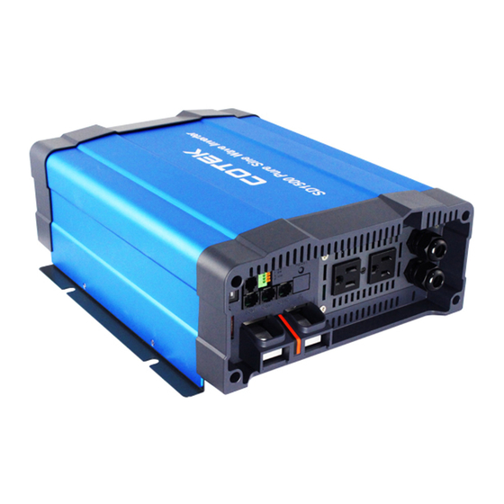
Summarization of Contents
Important Safety Information
1-1. General Safety Precautions
General safety precautions for operating the inverter, covering environmental exposure and wiring.
1-2. Precautions When Working with Batteries
Safety precautions related to handling batteries, including acid contact and avoiding sparks.
1-3. Installation
Guidelines for installing the inverter, focusing on location, ventilation, and avoiding hazards.
Functional Characteristics
2-1. General Information
Overview of SD-series inverters, features, and suitability for various applications.
2-2. Application
Lists various applications for the SD-series inverters.
2-3. Electrical Performance
Detailed electrical specifications for SD1500, SD2500, and SD3500 models, covering output, input, protection.
2-4. Mechanical Drawings
Diagrams and dimensions for SD series inverters, showing physical layout and measurements.
Introduction
3-1. Power ON / OFF / REMOTE (Main) switch
Describes the main power switch operation and its functions for the inverter.
3-2. LED Indicator
Explains the meaning of different LED indicators on the inverter for status and fault reporting.
3-3. DIP Switch (S1~S8) Assignment
Details the function of each DIP switch on the inverter for configuration and settings.
3-4. DC Input -
Instructions for connecting the negative DC input terminal, referring to wiring diagrams.
3-5. DC Input +
Instructions for connecting the positive DC input terminal, referring to wiring diagrams.
3-6. Chassis Ground
Guidance on connecting the chassis ground wire for safety compliance.
3-7. AC Output
Information on connecting the AC output, referring to hard wiring installation.
3-8. By-pass AC input
Instructions for connecting the by-pass AC input, referring to installation details.
3-9. AC input circuit breaker
Explanation of the AC input circuit breaker's function and reset procedure.
3-10. AC output socket
Details about the AC output socket and its specifications.
3-11. Reset Button
Information on the reset button functionality, typically for network settings.
3-12. CAN1 and CAN2 Port
Description of CAN ports for parallel operation and communication.
3-13. LCM Port
Details on the LCM port for connecting the LCD remote control panel.
3-14. Green terminal (Remote and Parallel select)
Explanation of the green terminal for remote control and parallel connection setup.
3-15. RS-232 Port
Information on the RS-232 port for serial communication and monitoring.
3-16. Fan Ventilation
Guidelines for ensuring adequate fan ventilation for the inverter.
3-17. Protections Features
Overview of the inverter's protection features against over/under voltage and overload.
DC Wiring Connections
4-1. DC Input Terminals
Details on connecting DC input terminals to the inverter, specifying voltage ranges.
4-2. Hard-wire Installation
Step-by-step guide for hard-wiring the inverter's AC connections for different models.
Parallel Mode
5-1. Prepare for Parallel Usage
Steps to prepare the inverters for parallel operation, including setting DIP switches and jumpers.
5-2. Industry Applications
Examples of parallel operation in various industry applications (1Φ2W, 1Φ3W, 3Φ4W).
5-3. Wiring for Parallel Usage
Guidelines and diagrams for wiring inverters for parallel connection.
5-4. AC Wiring Diagram
Wiring diagrams illustrating AC connections for parallel operation of 1Φ2W, 1Φ3W, and 3Φ4W systems.
5-5. Remote command for the parallel connection
Configuration steps for remote control of parallel connected inverters using RS-232.
5-6. Remove Parallel Connection
Procedures for safely disconnecting inverters that are connected in parallel.
RS-232 Command
6-1. RS-232 command introduction
Introduction to RS-232 commands for monitoring and controlling the inverter.
6-1-3. Command for accessing Setup Menus and adjusting values
Guide on using commands to access and modify inverter setup menus and parameters.
6-1-4. Setting interface
Explanation of the interface for setting over voltage, under voltage, and other protection parameters.


Need help?
Do you have a question about the SD1500 and is the answer not in the manual?
Questions and answers