Table of Contents
Advertisement
Quick Links
Advertisement
Table of Contents

Related Manuals for Cotek S1500-112


Summary of Contents for Cotek S1500-112
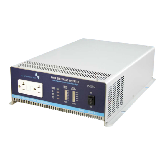
- Page 1 S1500 Series Pure Sine Wave Inverter User’s Manual...
-
Page 2: Table Of Contents
4. Troubleshooting……….……………………………………………………… 5. Maintenance…………………………………………………………………… 6. Warranty……………………………………………………………………….. 7. Appendices A…………………………………………………………………. Dip Switch (110V)………………………………….…………………... Dip Switch (220V)……………………………………………………… ©Copyright :This manual is the copyright of COTEK Electronic lnd. Co., Ltd. And may not be reproduced or copied without the express permission of the owner. - Page 3 10-3 CE (LVD EN609050-1) Declaration of Conformity…………………. 10-4 e-mark (e13 020932) Declaration of Conformity…………………… 10-5 UL (UL458) Declaration of Completion………………….………….. ©Copyright :This manual is the copyright of COTEK Electronic lnd. Co., Ltd. And may not be reproduced or copied without the express permission of the owner.
-
Page 4: Important Safety Information
1. Important Safety Information WARNING! Before installing and using the Inverter, you need to read these safety instructions carefully. 1-1. General Safety Precautions 1-1-1. Do not expose the Inverter to water, mist, snow, or dust. To reduce the risk of hazard, do not cover or obstruct the ventilation shaft. Do not install the Inverter in a zero-clearance compartment. -
Page 5: Features
2. Features Pure sine wave output (THD < 3%) Output frequency:50 / 60Hz switch selections Low power “Power Saving Mode” to conserve energy RS-232C interface / remote controls port Built – in Voltage and watt meter Thermostatically controlled cooling fan Advanced microprocessor Protection:Input low voltage Overload... -
Page 6: Electrical Performance
2-2. Electrical Performance Specification Model No. Item S1500-112 S1500-124 S1500-148 S1500-212 S1500-224 S1500-248 Continuous Output Power 1500W Surge Rating 2000W Input voltage ± ± 100 / 110 / 115 / 120V 200 / 220 / 230 / 240V Output Voltage Frequency ±... -
Page 7: Rear Panel Operation
2-3. Mechanical Drawing... -
Page 8: Instructions
3. Instructions This power inverter series is one of the most advanced line of mobile AC power systems. To get the most effective power inverter, it must be installed and used properly. Please read the instructions of this manual before you install and operate this model. - Page 9 3-1-4. Battery Voltage indicator: The AC load watt bar graph indicates the power drawn from the power inverter by the load. For the long-term operation of the watt indicator, it should remind in the green & orange area of the bar graph. The short-term operation of the watt indicator may be in the red area.
- Page 10 3-1-10. AC Outlet (Outlet sockets are available for the following countries): North America (GFCI) North America (NEMA 5-15R) Continental European (SCHUKO) Australia / New Zealand Universal United Kingdom...
-
Page 11: Rear Panel Operation
Connect DC input terminal to 12V / 24V / 48V battery or the other power sources. 【+】represents positive, and【-】represents negative. Reverse polarity connection will blow the internal fuse and may damage the inverter permanently. Model voltage Min voltage Max. voltage S1500-112 10.0 VDC 16.0 VDC S1500-212 S1500-124 20.0 VDC 32.0 VDC S1500-224 S1500-148 42.0 VDC... - Page 12 Over voltage Under Under Voltage Model Protection Voltage Shut- Shut- Shut- Restart Restart Restart Alarm down down down S1500-112 16.7VDC 15.2VDC 10.2VDC 9.5VDC 12.6VDC S1500-212 S1500-124 33.4VDC 30.4VDC 20.4VDC 19.0VDC 25.2VDC 85℃ 45℃ S1500-224 S1500-148 63.0VDC 61.8VDC 41.6VDC 42.0VDC 40.0VDC...
-
Page 13: Installation
3-4. Installation: Where to install. The power inverter should be installed in a location that meets the following requirements: 3-4-1. Dry - Do not expose the inverter to water. 3-4-2. Cool - The ambient temperature should be as cool as possible between 0℃... - Page 14 DC voltage drop across the cables from the inverter to the batteries. The longer or narrower the cables, the greater the voltage drop. Increasing your DC cable size helps improve the situation. Model No Wire AWG Inline Fuse S1500-112 200A S1500-212 200A S1500-124 130A S1500-224...
- Page 15 The cables should be high quality copper wiring and keep cable length as short as possible (a maximum of 3-6 feet). IN L IN E F U S E B A T T E R Y...
-
Page 16: Ac Safety Grounding
UL standards requires us to test and recommend specific GFCI. Cotek has tested the following GFCI – protected 20A receptacles and found that they functioned properly when connected to the output of the Inverter. -
Page 17: Inverter Operation
3-7. Inverter Operation: To operate the power inverter, use the ON / OFF switch on the Front panel to turn the power on. Then the power inverter is ready to deliver AC power to the loads. If you are operating several loads from the power inverter, turn them on separately after the inverter is on. - Page 18 WARNING! You may observe a spark when you make this connection since current may flow to charge capacitors in the power inverter. Do not make this connection with flammable fumes close by. Explosion or fire may occur. 3-7-5. Set the power switch to ON position. Check the meters and indicators in the front panel of the inverter.
-
Page 19: Power Output
3-8. Power Output: The inverter will operate most AC loads within its power rating. Considering that whether a microwave oven can be operated by the inverter or not, remember that the power commonly advertised for microwave ovens are the cooking power (the power delivered to the food), not the power actually consumed by the microwave oven. -
Page 20: Troubleshooting
4. Troubleshooting: WARNING! Do not open or disassemble the S600 Inverter. Attempting to service the unit yourself may cause the risk of electrical shock or fire. Problems and Symptoms Possible Cause Solutions Low output voltage Using average reading Use true RMS reading meter and cable voltmeter See page 15... -
Page 21: Maintenance
24 months from the date of purchase and will repair or replace any defective power inverters if you directly returned them to us with postage paid. Please note that Cotek is only responsible for ensuring our products are operational before delivering. -
Page 22: Appendices A
7. Appendices A 7-1. Dip Switch (110V) VOUT FREQ. BAUD (VAC) (Hz) RATE 1200 2400 ------ ------ 4800 ------ ------ 4800 7-2. Dip Switch (220V) VOUT FREQ. BAUD (VAC) (Hz) RATE 1200 2400 ------ ------ 4800 ------ ------ 4800 ※S4 is unavailable... -
Page 23: Appendices B
8. Appendices B 8-1. Operations of RS232 Serial Port 8-1-1. Hardware design: This unit uses a 9-pin D connector and three of RS232 signal lines: RECEIVE DATA (RXD):PIN2 TRANSMIT DATA (TXD): PIN3 DATA TERMINAL READY (DTR):PIN4 8-1-2. The connection between this unit and a computer is as follows: Computer Power Inverter 8-1-3. -
Page 24: Interface Command
8-2. Interface Command: The buffer size used for RS232 port is 12-bytes. This unit will ignore all bytes more than this value. During transmission, this unit (inverter) will indicate that it is ready to receive data from the computer by the DTR line. A computer has to check DTR line before sending any information to this unit. - Page 25 8-2-2-3. PWRS command: Power saving function control Format: PWRS < value> Illustration:A space (ASCll code 20H) is required between PWRS and < value > < value > can be one of the follows “0”:Power saving disable “1”:Power saving enable “2”:Inquire the status of saving the response information will be either “0”...
- Page 26 8-2-2-6. To query battery level command Format:BATT? Illustration:Adding any parameters is not required. To respond the result that Hexadecimal code is replaced by 2 ASCll code and is between 00 ~ 0B, you need to convert it into decade digit after obtaining a digit between 0 ~ 11. It can be one of the follows:...
- Page 27 8-2-2-7. To query load level command: Format:Load <> Illustration:Adding any parameters is not reuired. Respond:The same as BATT < value > < value > can be one of the follows: Hex Decade Indication code code Load < 5%, All of LED indicators go “OFF” Load <...
-
Page 28: Appendices C
9. Appendices C 9-1. Remote Control Operations:( Optional accessory ) System Configuration: 9-1-1. Plug the 9-pin D-SUB connector of the remote controller into the RS- 232 port of the Inverter. 9-1-2. Check the setting of DIP-SW S5 & S6, The communication BAUD RATE should be set to 4800bps (S5 &... - Page 29 Operations: 9-1-4. Set SLIDE SW “ON” (Keypads will not work if SLIDE SW is set “OFF”) 9-1-5. Remote ON/OFF:Pressing a button (and releasing in one second) will change (toggle) the output ON/OFF mode and the display of LED will be changed accordingly. 9-1-6.
-
Page 30: Power Saving Mode
9-2. Power saving mode MICROPROCESSOR BASED SINE WAVE INVERTER S-1500 SERIES ENABLING AND DISABLING POWER SAVING MODE 9-2-1. When the inverter is on and idle (there is no load or the load connected to the inverter has been switched off), it will still draw some power from the batteries for keeping the system alive. - Page 31 9-2-5. Following indications can be observed when the inverter is ON or the power saving “sleep” mode is enabled:( the default mode is that the inverter is OFF and all loads are disconnected ) 9-2-5-1. Switch on the inverter. You will hear two beeps and the green LED will start to flash with a sequence light as flash-flash- flash……About 3 seconds later, you are supposed to hear 1 beep.
- Page 32 9-2-6-3. Following indications can be observed when the inverter is ON or the power saving “sleep” mode is enabled:( the default mode is that the inverter is OFF and all loads are disconnected ) 9-2-6-3-1. Switch on the inverter. You are supposed to hear 2 beeps and green LED will start flashing with a sequence light of flash-flash-flash…..About 3 seconds later, you are supposed to hear 1 beep.
-
Page 33: Appendices
10-1. FCC (Class B) Declaration of Conformity:... -
Page 34: Ce (Emc En55022B) Declaration Of Conformity
10-2. CE (EMC EN55022B) Declaration of Conformity:... -
Page 35: Ce (Lvd En609050-1) Declaration Of Conformity
10-3. CE (LVD en60950-1) Declaration of Conformity:... -
Page 36: E-Mark (E13 020932) Declaration Of Conformity
10-4. e-mark (e13 020932) Declaration of Conformity:... -
Page 37: Ul (Ul458) Declaration Of Completion
10-5. UL (UL458) Notice of Completion... - Page 38 No. 33, Rong Hsin Rd., Pa Teh City, Tao Yuan County, Taiwan Phone:886-3-3661581 FAX:886-3-3676029 E-mail:sales@cotek.com.twT http:// www.cotek.com.tw 2005.08...
Need help?
Do you have a question about the S1500-112 and is the answer not in the manual?
Questions and answers