
Related Manuals for Bticino Polyx Memory Display


Summary of Contents for Bticino Polyx Memory Display
- Page 1 344163 Polyx Memory Display Manuale installatore • Installation manual Part. O0192B - 09/10-01 PC...
- Page 2 Polyx Memory Display ITALIANO eNgLIsh...
-
Page 3: Table Of Contents
Polyx Memory Display Indice 1 Introduzione Avvertenze e consigli Contenuto della confezione 2 Descrizione Funzioni principali Vista frontale Tasti funzioni videocitofoniche Tasti di navigazione Tasto funzione Segreteria Vista posteriore 3 Installazione Installazione a parete con base metallica a corredo 4 Configurazione rapida 5 Configurazione avanzata Flessibilità... -
Page 4: Introduzione
Pertanto Polyx Memory Display: – deve essere installato solo in ambienti interni; – non deve essere esposto a stillicidio o a spruzzi d'acqua; – deve essere usato unicamente su sistemi videocitofonici digitali 2 fili BTicino. Contenuto della confezione La confezione contiene: •... -
Page 5: Descrizione
Oltre a tutte le funzioni della videocitofonia digitale 2 fili, in im- pianti integrati con il sistema My Home Legrand multimedia, Polyx Memory Display permette di gestire la casa: dalla sicurezza al benessere sino all'intrattenimento (visualizzazione stato allarmi, diffusione sonora, regolazione temperatura singoli ambienti). -
Page 6: Vista Frontale
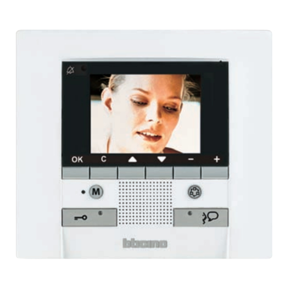
2 Descrizione Vista frontale 1 - Microfono. 2 - Display LCD a colori; visualizza i menù che guidano le operazioni di utilizzo e programmazione, mostra le immagini riprese dal posto esterno o da altre telecamere. 3 - Tastiera di navigazione; permette la navigazione all’interno dei menù, la conferma (tasto OK) o l’an- nullamento (tasto C) delle operazioni di programmazione. -
Page 7: Tasti Funzioni Videocitofoniche
Polyx Memory Display Tasti funzioni videocitofoniche Attivazione Posto Esterno/Ciclamento Attiva l'accensione del Posto Esterno associato e se presenti, permette il cicla- mento degli altri Posti Esterni/telecamere. Tasto serratura In connessione apre la serratura del Posto Esterno connesso, a riposo quella del Posto Esterno associato. -
Page 8: Vista Posteriore
Vista posteriore 1 - Connettore Mini-USB per il collegamento al PC 2 - Sede dei configuratori 3 - Connettore per alimentazione supplementare 4 - Microinterruttore ON/OFF di terminazione di tratta 5 - Collegamento al BUS del sistema digitale 2 fili BTicino... -
Page 9: Installazione
Dopo aver effettuato tutti i collegamenti fissare il Polyx Memory Display alla base avendo cura di disporre i fili in modo che non vengano danneggiati. Per estrarre il Polyx Memory Display dalla base abbassare la linguetta di fermo A servendosi di un cacciaviti, quindi spingere il Polyx Memory Display verso l'alto. -
Page 10: Configurazione Rapida
CONFIGURAZIONE RAPIDA TRAMITE CONFIGURATORE M Nota: se nell'appartamento è presente l'interfaccia d'appartamento 2 fili 346850 si consiglia di configu- rare Polyx Memory Display tramite Configurazione Avanzata. La configurazione rapida è raccomandata per impianti videocitofonici standard dove non sono richieste funzioni particolari ed è importante ridurre i tempi di installazione. - Page 11 IMPOSTA- ZIONI che rimanda ad una pagina dedicata alle impostazioni e con- figurazioni del dispositivo. Se il Polyx Memory Display è con- figurato con N=1 chiamo N=2. Se è INTERCOMUNICANTE I configurato con N=2 chiamo N=1.
- Page 12 4 Configurazione rapida INTERCOMUNICANTE: chiamata intercomunicante al Posto Interno con indirizzo uguale a quello del Polyx Memory Display aumentato di un numero pari a quello indicato dall'icona selezionata. (es.: INTERCOMUNICANTE IV chiamata intercomunicante indirizzata al Posto Interno con N+4) TELECAMERA: attivazione diretta della telecamera con indirizzo uguale a quello del Posto Esterno associato aumentato di un numero pari a quello indicato dall'icona selezionata.
-
Page 13: Configurazione Avanzata
Polyx Memory Display 5 Configurazione avanzata La Configurazione da PC, realizzabile tramite il software TiPolyxMemoryDisplay contenuto nel CD a corredo, consente di configurare la pagina principale del menù senza essere vincolati ad un set predefinito di funzioni. Ogni funzione può essere personalizzata per tipo, parametri e testo. -
Page 14: Personalizzazione Dei Testi
5 Configurazione avanzata Personalizzazione dei testi Possibilità di personalizzare tutte le voci presenti nei menù di Polyx Memory Display (es. SCENARIO IV = SCEN. Notte, COMUNICAZIONE = Intercom casa). Inoltre per i seguenti sistemi sarà possibile: ALLARMI • personalizzare i messaggi associando un testo descrittivo alla zona da cui proviene l'allarme •... -
Page 15: Altre Funzionalità
Polyx Memory Display Altre funzionalità SCENARI e COMUNICAZIONE Nella pagina iniziale sarà possibile aggiungere più di un richiamo per voci scenari e comunicazio- In questo modo si potrà inserire fino a 30 funzioni scenari o comunicazione. COMUNICAZIONE INTERCOMUNICANTE I SCENARIO I Nell'esempio è... -
Page 16: Collegamento Al Pc
Collegamento al PC Per trasferire la configurazione effettuata con il software TiPolyxMemoryDisplay o l'aggiornamen- to del firmware, collegare Polyx Memory Display al PC utilizzando un cavo USB-miniUSB. USB-miniUSB Affinchè la comunicazione possa avvenire, Polyx Memory Display deve essere alimentato e non... -
Page 17: Impostazioni
Polyx Memory Display 6 Impostazioni Dopo aver collegato Polyx Memory Display è possibile visionare e modificare le impostazioni di configurazione tramite il menù IMPOSTAZIONI. IMPOSTAZIONI CONFIGURAZIONE IMPOsTAZIONI RegOLAZIONI seRVIZI Per informazioni relative ai menù a lato consultare le Istruzioni d’uso contenute... -
Page 18: Menù Configurazione
6 Impostazioni Accesso al menù Configurazione Selezionare IMPOSTAZIONI Premere OK per confermare IMPOSTAZIONI Menù configurazione Selezionare CONFIGURAZIONE Premere OK per confermare CONFIGURAZIONE Viene visualizzato un messaggio di ATTENZIONE ! ATTENZIONE ! AREA RISERVATA ALLA Selezionare ESCI CONFIGURAZIONE DEL DISPOSITIVO! Premere OK per uscire >... -
Page 19: Opzioni
<NO> Effettuare la scelta <NO>/<SI> DEFAULT SLAVE – Polyx Memory Display configurato <SI> permette di installare più Polyx Memory Display configurati con lo stesso indirizzo N (max 3: 1 MASTER – 2 SLAVE). È consigliabile abilitare la Segreteria sul MASTER; se si volesse... -
Page 20: Configurazione Posto Interno
6 Impostazioni 6.1.2 Configurazione posto interno Selezionando CONFIGURAZIONE PI è possibile modificare l'indirizzo (N) di Polyx Memory Display e/o del Posto Esterno associato (P). OPZIONI Selezionare CONFIGURAZIONE PI PARAMETRI MODALITA' > CONFIGURAZIONE PI RESET Premere OK per confermare Selezionare INDIRIZZO (N) e/o (P) CONFIGURAZIONE PI >... -
Page 21: Reset
Polyx Memory Display 6.1.3 Reset Selezionando RESET si cancellano tutti i dati e si riporta Polyx Memory Display alle impostazioni di fabbrica. OPZIONI Selezionare RESET PARAMETRI MODALITA' CONFIGURAZIONE PI > RESET Premere OK per confermare Viene visualizzato il seguente messaggio... -
Page 22: Come Risolvere Eventuali Inconvenienti
7 Come risolvere eventuali inconvenienti Modalità push to talk Ricezione di una chiamata dal posto esterno. Premere il tasto Connessione per rispondere alla chiamata. Il led connessione è acceso. Durante la conversazione è possibile attivare la funzione PUSH TO TALK. Premere il tasto Connessione per almeno 2 secondi per parlare con il posto esterno. - Page 23 - verificare la regolazione dei volumi su Polyx Me- mory Display; - verificare che non siano presenti forti sorgenti ru- Al posto interno è difficoltoso sentire chi parla morose in prossimità di Polyx Memory Display - è possibile comunicare in modalità PUSH TO TALK (vedi paragrafo relativo).
-
Page 24: Appendice
Servizio Tecnico Clienti BTicino risponde del perfetto funzionamento del dispositivo solo se installato a regola d’arte rispettando le indicazioni del manuale d’installazione del prodotto. In caso di malfunzionamento contattare il Centro Assiatenza Tecnica Autorizzato. - Page 25 Polyx Memory Display Contents 1 Introduction Warnings and tips Package content 2 Description Main functions Front view Video door entry function keys Navigation keys Key for answering machine functions Rear view 3 Installation Wall installation with metal base supplied 4 Quick configuration...
-
Page 26: Introduction
Thus the Polyx Memory Display: – must only be installed indoors; – must not be exposed to drips or splashes of water; – must only be used on BTicino digital 2-wire video door entry systems. Package content The package contains: •... -
Page 27: Description
2 Description Main functions The BTicino Polyx Memory Display is the evolution of the video handset which can be used in managing the home system. As well as all the 2-wire digital door entry functions, in systems com- bined with the My Home Legrand multimedia system, Polyx Memory Display can manage the home: from security to well-being to entertainment (display of the alarm state, sound system, temperature setting in single rooms). -
Page 28: Front View
2 Description Front view 1 - Microphone. 2 - Colour LCD display; displays the menus which guide the use and programming operation, shows the pictures taken by the entrance panel or other cameras. 3 - Navigation keypad; navigates inside the menus, confirms (OK key) or cancels (C key) the program- ming operations. -
Page 29: Video Door Entry Function Keys
Polyx Memory Display Video door entry function keys Activation Entrance Panel/Cycling Activates the switching ON of the associated Entrance Panel and cycles any other Entrance Panels/cameras. Door lock key In connection opens the door lock of the connected Entrance Panel, at rest that of the associated Entrance Panel. -
Page 30: Rear View
2 Description Rear view 1 - Mini-USB connector for connection to the PC 2 - Configurator socket 3 - Connector for extra power supply 4 - Stretch end ON/OFF microswitch 5 - Connection to the BTicino 2-wire digital system BUS... -
Page 31: Installation
After making all the connections fasten the Polyx Memory Display to the base being careful to ar- range the wires so that they are not damaged. To take the Polyx Memory Display out of the base lower stop tab A using a screwdriver, then push the Polyx Memory Display upwards. -
Page 32: Quick Configuration
4 Quick configuration QUICK CONFIGURATION BY MEANS OF M CONFIGURATOR Note: If the apartment has the 2-wire apartment interface 346850 the Polyx Memory Display should be configured using Advanced Configuration. The quick configuration is recommended for standard video door entry systems where no special functions are required and short installation times are important. - Page 33 SETTINGS which goes to a page dedicated to the device settings and configurations. If the Polyx Memory Display is con- figured with N=1, call N=2. If it is con- INTERCOMMUNICATING I figured with N=2, call N=1.
- Page 34 4 Quick configuration INTERCOMMUNICATING: intercommunicating call to the Handset with the same address as the Polyx Memory Display increased by a number equal to that indicated by the icon selected. (e.g.: INTERCOMMUNICATING IV intercommunicating call address to the Handset with N+4) CAMERA: direct activation of the camera with the same address as the associated Entrance Panel increased by a number equal to that indicated by the icon selected.
-
Page 35: Advanced Configuration
Polyx Memory Display 5 Advanced configuration Configuration from PC by means of the TiPolyxMemoryDisplay software in the CD supplied lets you configure the main menu page without being limited to a predefined set of functions. The type, parameters and text of each function can be customised. -
Page 36: Customisation Of Texts
5 Advanced configuration Customisation of texts The items in the Polyx Memory Display menu (e.g. SCENARIO IV = Night SCEN, COMMUNICATION = Intercom in the home) can be customised. The following are also possible for the following systems: ALARMS • customise the messages associating a descriptive text to the zone where the alarm comes from •... -
Page 37: Other Functionalities
Polyx Memory Display Other functionalities SCENARIOS and COMMUNICATION More than one call for scenarios and communication can be added in the first page. In this way up to 30 scenario or communication functions can be entered. COMMUNICATION INTERCOMMUNICATING I SCENARIO I In the example at the side 12 communication functions and 18 scenarios can be entered. -
Page 38: Connection To The Pc
To transfer the configuration made with the TiPolyxMemoryDisplay software or update the firmware, connect the Polyx Memory Display to the PC using USB-miniUSB cable. USB-miniUSB In order for the communication to occur, the Polyx Memory Display must be powered and not physically configured. -
Page 39: Settings
Polyx Memory Display 6 settings After configuring the Polyx Memory Display, you can view and modify the configuration settings in the SETTINGS menu. SETTINGS CONFIGURATION seTTINgs ADJUsTMeNT seRVICes For information about these menus please consult the User guide in the CD en- MessAges closed. -
Page 40: Configuration Menu
6 settings Access to the Configuration menu Select SETTINGS Press OK to confirm SETTINGS Configuration menu Select CONFIGURATION Press OK to confirm CONFIGURATION A WARNING message is displayed ! WARNING ! AREA RESERVED FOR Select QUIT CONFIGURATION OF THE DEVICE Press OK to quit >... -
Page 41: Options
ENABLE ANSW. MACHINE <NO> Select <NO>/<YES> DEFAULT SLAVE – the Polyx Memory Display configured <YES> allows the installation of several Polyx Memory Displays configured with the same N address (max. 3: 1 MASTER – 2 SLAVE). It is recommended that the Answering Machine is enabled on the MASTER;... -
Page 42: Handset Configuration
6 settings 6.1.2 Handset configuration On selecting H CONFIGURATION the address (N) of the Polyx Memory Display and/or the associ- ated Entrance Panel (P) can be edited. OPTIONS Select H CONFIGURATION PARAMETER MODE > H CONFIGURATION RESET Press OK to confirm... -
Page 43: Reset
Polyx Memory Display 6.1.3 Reset Selecting RESET cancels all the data and returns the Polyx Memory Display to the factory settings. OPTIONS Select RESET PARAMETER MODE H CONFIGURATION > RESET Press OK to confirm The following message is displayed CANCEL THE... -
Page 44: Trouble Shooting
7 Trouble shooting Push to talk mode Receiving a call from the entrance panel. Press the Connection key to answer the call. The LED is ON. During the conversation you can activate the PUSH TO TALK function. Press the Connection key for at least 2 seconds to talk to the entrance panel. - Page 45 - check that it has not been set as “Slave”. does not switch on - talk at a maximum distance of 40 centimetres from the Polyx Memory Display microphone; - reduce the volume of the entrance panel micro- At the entrance panel it is difficult to hear the caller phone;...
-
Page 46: Appendix
Technical After-Sales Service BTicino only accepts responsibility for perfect device operation if it is installed to the state of the art respecting the indications of the product installation manual. www.bticino.com... - Page 48 Timbro installatore Installer stamp BTicino SpA si riserva il diritto di variare in qualsiasi momento i contenuti illustrati nel presente stampato e di comunicare, in qualsiasi forma e modalità, i cambiamenti apportati. BTicino SpA reserves at any time the right to modify the contents of this booklet and...
Need help?
Do you have a question about the Polyx Memory Display and is the answer not in the manual?
Questions and answers