R82 Panther User Manual
Hide thumbs
Also See for Panther:
- Mounting instructions (7 pages) ,
- Mounting instruction (5 pages) ,
- Mounting instruction (11 pages)

Related Manuals for R82 Panther


Summary of Contents for R82 Panther
- Page 1 English user manual © 2009 R82 A/S. All rights reserved. The R82 logo and the Panther chairs are registered trademarks of R82 A/S. 11.2011...
-
Page 2: Table Of Contents
CONTENTS Panther ................3 Safety ................4 Tools .................. 4 Maintenance ..............4 Warranty ................5 In and out of the chair ............5 Roadability 1/4 ..............6 Roadability 2/4 ..............7 Roadability 3/4 ..............8 Roadability 4/4 ..............9 Quick release (QR) ............ -
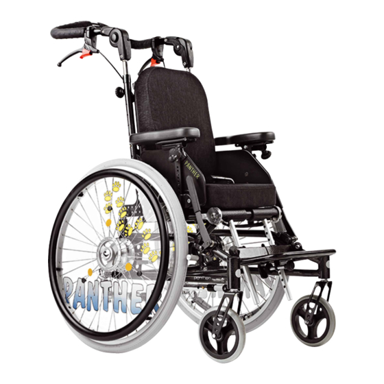
Page 3: Panther
Panther will provide your child with exceptional postural support and comfort. The Panther is for both in- and outdoor use and it is available in four sizes and suitable for children age 2 - 14 years, who suffers from paralysis, hypsarrhytmia etc. -
Page 4: Safety
SAFETY The Panther has earned the CE-mark. This certifies that it meets all re- levant European safety requirements. Further the Panther is approved according to ISO 7176/19-2001, EN 12812 and EN12183. The durability of this product is 5 years when it is used on a daily basis. -
Page 5: Warranty
Instructions about getting in and out of the wheelchair is delivered by the R82 A/S therapists, when the Pan ther is purchased. Before placing the child into the Panther, the brake has to be pulled and the footplate must be angled backwards under the seat. -
Page 6: Roadability 1/4
ROADABILITY 1/4 Driving UP kerbs (max. 10 cm) Forwards This technique is recommended for the experi- enced users. * Make sure the anti-tip device is deactivated * Drive forward towards the kerb * Balance on the rear wheels and lift the front wheels from the ground. -
Page 7: Roadability 2/4
ROADABILITY 2/4 Driving DOWN kerbs (max. 10 cm) Forwards This technique is recommended for the experi- enced users. * Make sure the anti-tip device is deactivated * Drive forward towards the kerb * Pull hard on the hand rims and drive forward. All wheels will touch the ground a the same time. -
Page 8: Roadability 3/4
ROADABILITY 3/4 Driving DOWN/UP a hill Follow the below to avoid tilting when driving down/up a hill. Driving down: Sit upright in the chair. Correct the speed with the hand rims and not with the brakes. Driving up: Bend forward to correct the point of gravity. Avoid to turn around in the middle of the hill. -
Page 9: Roadability 4/4
ROADABILITY 4/4 Driving UP stairs Always ask for help. Never enter an escalator even with help from others. Backwards, with assistance: * Make sure the anti-tip device is deactivated and the handles is tightned securely. * Drive backwards toward the first step. * Tilt the chair and pull up the chair one step at a time. -
Page 10: Quick Release (Qr)
(A): Remove the hub shell. Then push and hold the release button. Pull the wheel. If your Panther has QR front wheels, they are removed in the following way: Push the release button as shown. Pull front fork and wheel down (B). -
Page 11: Brakes & Anti-Tip Device
To activate the anti-tip device: Push down as shown (B) and turn 180 The anti-tip device always has to be activated, when the wheelchair is tilted. However is the Panther is moved the anti- tip device has to be deactivated, as it could be bumping against something. -
Page 12: Central Brake
CENTRAL BRAKE To mount the central brake on the Panther frame, the instruction below must be followed: * Mount the fitting with the bar for the brake, on the front of the frame (A) with the 4 enclosed Allen screws. -
Page 13: Seat & Back Rest Angling
SEAT & BACK REST ANGLING To tilt the seat: Press down the pedal (A) under the seat, re- leasing the gas spring. Adjust by grapping the handles. The angle between the back and seat remains the same. To angle the Back Rest: Pull the wire (B) behind the back rest below while holding and adjusting the back rest with the other hand. -
Page 14: Gasspring Adjustment
GASSPRING ADJUSTMENT The Panther is equipped with a gasspring to regulate the angle. After a period the gasspring might need to be adjusted. The adjustment is only neccessery when: - the gasspring releases itself - the gasspring can not be released at all If the gasspring releases itself;... -
Page 15: Seat Placement
SEAT PLACEMENT The placement of the seat on the frame can be changed. You have the possibility to change: - seatheight - seat angling interval - seat placement forth and back The adjustment possibilities are illustrated on the above drawing. (A) is for adjustment of the seatheight. -
Page 16: Rear Wheel Positions
REAR WHEEL POSITIONS Above we have described the positions of rear wheels we recommend. If a different seat height is required, adjust the height according to the description, page 11. To obtain the best stability, use the holes in the back row (D). -
Page 17: Choise Of Front Fork At Different Seat Heights
2 175 x 40 mm (QR) ons to avoid influencing the stability of the pos 2 180 x 45 mm (QR) Panther negatively. pos 3 140 x 40 mm / 5,5" (QR) SH:48 cm (std) pos 1 pos 1... -
Page 18: Foot Supports
To angle adjust the foot support bar, pull the strap in front of the seat (D). When angling the foot support bar on Panther size 3, it is nec essary to adjust the seatheight. Mounting the foot straps (E). +87°... -
Page 19: Armrests And Splashboards
ARMRESTS AND SPLASHBOARDS The armrests are placed in the fittings on both sides of the seat. The height of the armrests is determined by the splash boards hitting the fittings. To adjust the height of the armrests, move the splashboards up/down the armrest bars. -
Page 20: Pommel And Back Extension
POMMEL AND BACK EXTENSION The fittings for the pommel are to be mounted under the seat cushion with the 4 mm Allen key. Then place the pommel in the fittings as shown (A). Tighten under the seat. Mount the back extension in the head support fit- tings on the back as shown (B). -
Page 21: Head Supports
HEAD SUPPORTS Mounting and height adjustment of the head support (A). To increase forward head support turn the device 180 Angle and lateral adjustment of the head sup- port (B). It is easiest to loosen all adjustment mechanisms at once, set the device in the de- sired position, and then tighten the mechanisms again. -
Page 22: Swing-Away Shoulder Supports
SWING-AWAY SHOULDER SUPPORTS To height and depth adjust the shoulder sup- ports, use the 6 and 4 mm Allen keys (A). To swing away the shoulder supports, pull the little black knobs as shown above (B). To mount back extension, head support and swing-away shoulder supports at the same time, use the head support bar as through bar (C). -
Page 23: Swing Away Side Supports
SWING AWAY SIDE SUPPORTS The swing away side supports are mounted with screws through the slots in the back rest (A). Place the side supports in the right height and width before tightening the screws com pletely. To swing away the side supports, press down the red button (B). -
Page 24: Thermo Bag And Tain Cape
THERMO BAG AND TAIN CAPE Placing the thermo bag: Unzip the thermo bag and place it in the chair as shown. Place the child on the bag, bring up the top and zip. Fasten the shoulder straps in the spring lock (A). The thermo bag has velcro at the foot, enabling you to remove the top completely - a good idea f.ex. -
Page 25: Abduction Strap
ABDUCTION STRAP Place the abduction strap flat on the seat as shown. Fasten the rear straps in the buckles under the seat (A). Place the child and bring the straps up between the child’s thighs and around the back of the chair as shown. -
Page 26: Crossvest And Vest
CROSSVEST AND VEST Fasten the shoulderstraps in the mounting on the back (A). Fasten the side and the lower straps in the buckles behind the cushions (B) + (C). Both vest and crossvest can be dismounted where the straps are attached to the vest itself. That way you don’t need to loosen the buckle everytime. -
Page 27: Drum Brakes 1/3
DRUM BRAKES 1/3 How to mount drum brakes: 1. Dismount the wheel. 2. Use a 24 mm key to dismount the QR-axle. If you need to just move the QR-axle to another hole, the distance between the nuts on the out- side of the plate, must be 9 mm. -
Page 28: Drum Brakes 2/3
The drum brake is mounted in the plate. Consi- dering which Panther you have, follow descrip- tion 1 or 2. 1. To mount the drum brake on a Panther with camber, follow the drawing. To clean the thread you may want to use a 5 mm tape tap. -
Page 29: Drum Brakes 3/3
DRUM BRAKES 3/3 The handle i smounted on the push brace with a screw driver (A). Lead the inner cable through the hole in the screw (B) and mount the outer cable (C). To fasten the cable at the brake: Lead the cable through the holder (D) and through the hole in the screw (E). -
Page 30: Mounting The 12½" Wheel
MOUNTING THE 12½” WHEEL How to mount the 12½” wheel: 1. Dismount the wheel 2. Use a 24 mm key to dismount the QR-axle 3. Dismount the anti-tipping devices at both sides 4. Mount the 12” wheels from behind and fa- sten with the screws from the anti-tipping devices 5. -
Page 31: Mounting/Adjusting The Hand Brake & Cable
MOUNTING/ ADJUSTING THE HAND BRAKE & CABLE The handle is mounted on the push brace with a screw driver (A). Lead the inner cable through the hole in the screw (B) and mount the outer cable (C). To fasten the cable at the brake: Lead the cable through the holder (D) and through the hole in the screw (E). -
Page 32: Transportation/Storage
TRANSPORTATION/ STORAGE It is possible to fold the Panther wheelchair for transportation or storage: A Loosen the handles B Turn the handles towards the middle of chair. C Angle the backrest forward D Angle the footrest backwards underneath the chair. -
Page 33: Transportation In Motor Vehicles 1/2
TRANSPORTATION IN MOTOR VEHICLES 1/2 The Panther wheelchair is approved for trans- porting children in motor vehicles, when the wheelchair is placed in forward-facing position. The approval is not valid on special made wheelchairs. Follow the below to ensure the safety:... -
Page 34: Transportation In Motor Vehicles 2/2
TRANSPORTATION IN MOTOR VEHICLES 2/2 1. Secure the Panther in the vehicle: * Mount the 4-point strap-type tiedown sy- stem in the vehicle. (Follow the manufacture instructions) * Mount the two fittings (A) with the symbol (B) on the back of the chair. -
Page 35: For Carriage On Public Transport
FOR CARRIAGE ON PUBLIC TRANSPORT In accordance with Direktive 2001/85/EG, An- nex VII, item 3.8.3, the vehicle includes spe- cially marked wheelchair locations, permitting transport with the wheelchair facing the forward direction of movement. If this method of transport is utilised, the user or carer must play an active part in the travel, be prepared for rapid movements, and the ability to maintain a secure seated position throughout... -
Page 36: Product Identifikation
PRODUCT- IDENTIFIKATION A) Serial number The label is placed on the frame just below the seat. B) Manufacturer The label is placed on the frame just below the seat. Dato: 31-01-02 Belast: kg 0840-01-111878-001 Varenr: 880003 5707292 134158 Parallelvej 3 DK-8751 Gedved... -
Page 37: Measurements
MEASUREMENTS Size 1 Size 2 Size 3 Size 4 cm (inch) cm (inch) cm (inch) cm (inch) Seat width (A) 28 (11") 32 (12½") 36 (14") 40 (16") Seat depth (B) 20-29 (8-11½") 26-35 (10-13½") 30-39 (12-15¼") 30-39 (12-15¼") Back height (C) 38 (15") 40 (16") 44 (18") -
Page 38: Techinical Data
TECHINICAL DATA Frame: Powder lacquered steel Plastic parts: Glassfiber strengthened polyprolene Cushions: Fire-resistant foam Cover: Velour with incontinence foil on the back DISTRIBUTOR PRODUCER R82 A/S Parallelvej 3 8751 Gedved Denmark Please find your distributor on www.R82.com...
Need help?
Do you have a question about the Panther and is the answer not in the manual?
Questions and answers