Table of Contents
Advertisement
P/N: IS3220VSC
Rev: B
__________________________________________________________________________________________
OWNER'S MANUAL
INSTALLATION, OPERATION, & PARTS
TriStar Energy Solution
TM
Variable Speed Pump Control
The Hayward TriStar Pump is specifically engineered for the demanding requirements of today's inground swimming pool/spa that is
equipped with large capacity filters, heaters, and pool cleaning equipment. The TriStar is a selfpriming pump that includes an
improved seal and impeller design that will provide many years of efficient, dependable, corrosionfree service. The advanced design
provides superior performance while reducing maintenance requirements. NOTE To prevent potential injury and to avoid
unnecessary service calls, read this manual carefully and completely.
WARNING
–
The TriStar ES (Energy Solution) variable speed pump control is designed for use only with
Hayward SP322063EEV 2.7 THP 3 phase pump. Do not use with any other pump models. Use of this control with any other pump
model will void warranty. Refer to TriStar Owner's Guide (IS3200) for all applicable pump installation, operation, and
troubleshooting information.
SAVE THIS INSTRUCTION MANUAL
HAYWARD POOL PRODUCTS
620 DIVISION STREET ELIZABETH, NJ 07207 (908) 3515400
WWW.HAYWARDPOOL.COM
Advertisement
Table of Contents

Related Manuals for Hayward TriStar SP322063EEV


Summary of Contents for Hayward TriStar SP322063EEV
- Page 1 P/N: IS3220VSC Rev: B __________________________________________________________________________________________ OWNER’S MANUAL INSTALLATION, OPERATION, & PARTS TriStar Energy Solution TM Variable Speed Pump Control The Hayward TriStar Pump is specifically engineered for the demanding requirements of today’s inground swimming pool/spa that is equipped with large capacity filters, heaters, and pool cleaning equipment. The TriStar is a selfpriming pump that includes an improved seal and impeller design that will provide many years of efficient, dependable, corrosionfree service. The advanced design provides superior performance while reducing maintenance requirements. NOTE To prevent potential injury and to avoid unnecessary service calls, read this manual carefully and completely. WARNING – The TriStar ES (Energy Solution) variable speed pump control is designed for use only with Hayward SP322063EEV 2.7 THP 3 phase pump. Do not use with any other pump models. Use of this control with any other pump model will void warranty. Refer to TriStar Owner’s Guide (IS3200) for all applicable pump installation, operation, and troubleshooting information. SAVE THIS INSTRUCTION MANUAL HAYWARD POOL PRODUCTS 620 DIVISION STREET ELIZABETH, NJ 07207 (908) 3515400 WWW.HAYWARDPOOL.COM...
-
Page 2: Important Safety Instructions
WARNING – This product should be installed and serviced only by a qualified professional. CAUTION – All electrical wiring MUST be in conformance with all applicable local codes, regulations, and the National Electric Code (NEC). Use of nonHayward replacement parts voids warranty. ATTENTION INSTALLER – THIS MANUAL CONTAINS IMPORTANT INFORMATION ABOUT THE INSTALLATION, OPERATION, AND SAFE USE OF THIS PUMP THAT MUST BE FURNISHED TO THE END USER OF THIS PRODUCT. FAILURE TO READ AND FOLLOW ALL INSTRUCTIONS COULD RESULT IN SERIOUS INJURY. WARNING – ... - Page 3 ATTENTION: Si l'installation est visee par la section 68 du code Canadien de l ielectricite, premiere partie, brancher uniquement a une derivation protegee par un disjoncteur differentiel de classe A. WARNING – Suction Entrapment Hazard. Suction in suction outlets and/or suction outlet covers which are damaged, broken, cracked, missing, or unsecured cause severe injury and/or death due to the following entrapment hazards: Hair Entrapment Hair can become entangled in suction outlet cover. Limb Entrapment A limb inserted into an opening of a suction outlet sump or suction outlet cover that is damaged, broken, cracked, missing, or not securely attached can result in a mechanical bind or swelling of the limb. Body Suction Entrapment A differential pressure applied to a large portion of the body or limbs can result in an entrapment. Evisceration/ Disembowelment A negative pressure applied directly to the intestines through an unprotected suction outlet sump or suction outlet cover which is damaged, broken, cracked, missing, or unsecured can result in evisceration/disembowelment. Mechanical Entrapment There is potential for jewelry, swimsuits, hair decorations, fingers, toes, or knuckles to be caught in an opening of a suction outlet cover resulting in mechanical entrapment. WARNING To Reduce the risk of Entrapment Hazards: When outlets are small enough to be blocked by a person, a minimum of two functioning suction outlets per pump must be installed. Suction outlets in the same plane (i.e. floor or wall), must be installed a minimum of three feet (3’) [0.91 meter] apart, as measured from near point to near point. Dual suction fittings shall be placed in such locations and distances to avoid “dual blockage” by a user. Dual suction fittings shall not be located on seating areas or on the backrest for such seating areas. The maximum system flow rate shall not exceed the values shown in the “Pipe Sizing Chart” found at the bottom of page 5 of the TriStar Owner’s Guide (IS3200). Never use pool or spa if any suction outlet component is damaged, broken, cracked, missing, or not securely attached. Replace damaged, broken, cracked, missing, or not securely attached suction outlet components immediately. In addition to two or more suction outlets per pump installed in accordance with latest IAF (formerly NSPI) standards and CPSC guidelines, follow all national, state, and local codes applicable. Installation of a vacuum release or vent system, which relieves entrapping suction, is recommended. WWW.HAYWARDPOOL.COM USE ONLY HAYWARD GENUINE REPLACEMENT PARTS ...
-
Page 4: General Information
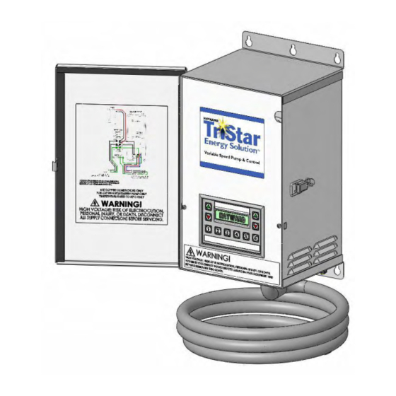
OPEN when starting the circulation system. Failure to do so could result in severe personal injury and/or property damage. WARNING – Never operate or test the circulation system at more than 50 PSI maximum. WARNING – Fire and burn hazard. Motors operate at high temperatures and if they are not properly isolated from any flammable structures or foreign debris they can cause fires, which may cause severe personal injury or death. It is also necessary to allow the motor to cool for at least 20 minutes prior to maintenance to minimize the risk for burns. WARNING – Failure to install according to defined instructions may result in severe personal injury or death. General Information Introduction This manual contains information for the proper installation and operation of the Hayward TriStar Energy Solution Variable Speed Pump Control. The instructions in this manual MUST be followed precisely. Failure to install according to defined instructions will void warranty. Control Features & Benefits · 6 programmable speeds allow you to size the pump to your pool, maximize energy efficiency so you use just enough electricity for each specific task, provide greater flexibility for spa and water features, and improve water circulation quality. · Extremely quiet operation, providing flexibility of placement for your equipment pad. · 24 hour programmable clock to customize each speed’s length of operation. · Wall mounted enclosure provides easy access. · 6 speed interface is easy to program and use, providing superior energy management by defaulting to a “Low Filter” speed to filter your pools water. · Easy to use membrane touchpad. -
Page 5: Installation And Wiring
Wire Size: 12 AWG Use copper conductors only. For indoor/outdoor use. A disconnecting means located within sight of this control, and at least 5 ft. from the inside wall of the pool, spa, or hot tub, must be provided. Voltage Voltage at control and motor MUST NOT be more than 10% above or below motor name plate rated voltage, or components may overheat, causing overload tripping and reduced component life. If voltage is less than 90% or more than 110% of rated voltage when motor is running at full load, consult power company. Grounding And Bonding Install, ground, bond, and wire control and motor in accordance with local or national electrical code requirements. Permanently ground control and motor. Use green ground terminal provided under motor canopy or access place; use size and type wire required by code. Connect control and motor ground terminals to control enclosure ground. Bond control and motor to pool structure. Bonding will connect all metal parts within and around the pool with a continuous wire. Bonding reduces the risk of a current passing between bonded metal objects, which could potentially cause electrical shock if grounded or shorted. Reference NEC codes for all wiring standards including, but not limited to, grounding, bonding and general wiring procedures. Use a solid copper conductor, size 8 or larger. Run wire from external bonding lug to 2 reinforcing rod or mesh. Connect a No. 8 AWG (8.4 mm ) solid copper bonding wire to the pressure wire connector provided on the control and motor housings and to all metal parts of swimming pool, spa, or hot tub, and to all electrical equipment, metal piping (except gas piping), and conduit within 5 ft. (1.5 m) of inside walls of swimming pool, spa, or hot tub. Wiring WARNING – All electrical wiring MUST conform to local codes, regulations, and the National Electric Code (NEC). Control and pump MUST be permanently connected to circuit. If other lights or appliances are also on the same circuit, be sure to add their amp loads before calculating wire and circuit breaker sizes. Use the load circuit breaker as the Master On Off switch. If the variable speed pump and control are being used to replace an existing pump that was controlled by a separate mechanical time clock, the control should be connected directly to the line power supply, bypassing the time clock. The time clock can then be used to power other equipment (such as a heater, heat pump, or booster pump) that requires the filter pump to be operating when used. If the time clock is used in this manner, it should be set to power the equipment during a time cycle when the variable speed pump is operating at an appropriate flow rate, as defined by the steps set in the sequencer menu. WWW.HAYWARDPOOL.COM USE ONLY HAYWARD GENUINE REPLACEMENT PARTS ... -
Page 6: Installation Notes
TriStar Variable Speed Pump Control ____ ____________________________Page 6 of 16 Installation Notes 1. TURN OFF THE ELECTRICAL POWER AT THE CIRCUIT BREAKER. 2. Find a location for the SP3220VSC on a vertical flat surface, out of the direct sunlight, which will not be flooded, and above the pump. This location must be within 8 feet of the pump. Mount the control enclosure to this location using the provided attachment points. The control must be mounted such that the enclosure vents are free from obstructions and the door may be opened without issue. Do not mount the control enclosure inside a panel or tightly enclosed area, or directly to the side of a house. 3. Open door and remove panel containing control interface by removing two screws. Disconnect interface cable from Emerson SK drive, and place interface panel in a safe location away from water such that the interface does not make contact with anything. 4. Connect 230VAC line power supply wiring to terminal block and ground strip as shown. Spade terminals with upturned lugs must be used to connect wiring to terminal block. 5. Connect included phase wiring from control to pump wiring marked #13 as shown in wiring diagram below. Connect green ground wire to motor ground screw. 6. Connect the control to the pool bonding system using 8AWG (6AWG for Canada) wire. A lug for bonding is provided on the outside/bottom of the enclosure. 7. After all electrical connections have been made, reconnect interface cable plug to Emerson SK drive, and replace interface panel using two screws. 8. Apply power to the system, and proceed to “Installer Initial Setup” on page 7. Wiring Diagram WWW.HAYWARDPOOL.COM USE ONLY HAYWARD GENUINE REPLACEMENT PARTS ... - Page 7 Press Time Up/Dn buttons to PICK PRIME MODE 2 complete. select desired prime mode *MORE THAN 5 FT (prime mode should be selected *5 FEET OR LESS based on height of pump inlet above water level in pool). Press 6 (OK) to store current settings. Prime mode selection Timer disabled: pump Use 1 – 6 buttons to switch *PRIME MODE* is complete. runs according to prime pump to a preset mode. Use (when timer is disabled) mode selected, and Time Up/Dn buttons to cause defaults to P2. remaining time for current mode *PUMP STOPPED* Timer enabled: pump to increase/decrease by 5 (when timer is enabled, until remains stopped until minutes. Use % Flow Up/Dn system time reaches TimerOn system time reaches buttons to change pump speed setting) TimerOn setting. within predefined range. WWW.HAYWARDPOOL.COM USE ONLY HAYWARD GENUINE REPLACEMENT PARTS ...
- Page 8 TriStar Variable Speed Pump Control ____ ____________________________Page 8 of 16 VARIABLE SPEED INTERFACE – INITIAL SETUP NOTES: 1 ) When power is applied to the system for the first time, or if initial setup override is engaged, the user will have to set the system language, clock, and prime mode before the pump will operate. During the initial system setup, the 1 (Exit) button is not active. The user must make these selections before the system will allow the pump to operate. If a mistake is made during the initial setup, the user may override the incorrect setup by disconnecting power to the system, and reapplying power while pressing the 4 button. The language and clock settings may be changed after initial system setup as shown in the Installer Setup chart if needed. 2 ) The user must select the prime mode based on the layout of their pump installation. Choose “MORE THAN 5 FT” if the inlet of the pump is more than 5 feet above the water level in the pool, or choose “5 FEET OR LESS” if the inlet of the pump is 5 feet or less above the water level in the pool. WWW.HAYWARDPOOL.COM USE ONLY HAYWARD GENUINE REPLACEMENT PARTS ...
- Page 9 This menu allows the To change day of week or time of *SET Sun 7:36pm user to set the current day, confirm by pressing 6 (OK) (for example) day of week and time button. An underlining cursor CLOCK/TIMER function of day, as well as will appear below dayofweek enable or disable the value. timer function, and define the timer “on” Press 5 (Next) or 2 (Prev) to *SET Sun 7:36pm and “off” time. select either dayofweek, hours, *SET Sun 7:36pm or minutes with underlining *SET Sun 7:36pm cursor. Press Time Up/Dn buttons to change selected value. Pressing 6 (OK) causes system to *CLOCK SAVED! store preset current time. Pressing 5 (Next) allows the user *TIMER ENABLED to enable or disable the Timer. *TIMER DISABLED Use Time Up/Dn buttons to select between Timer Enable or Timer Disable. Pressing 6 (OK) causes *TIMER SAVED! system to store this option. WWW.HAYWARDPOOL.COM USE ONLY HAYWARD GENUINE REPLACEMENT PARTS ...
- Page 10 SEQUENCER function duration for each Use % Flow Up/Dn to select *S1:P3 1h45min sequence step, which desired active preset for displayed *S1:STOP 3h30min should be customized sequence step, or to select Stop *S1:EMPTY for each installation. Mode or Empty. If Empty is Use 5 (Next) or 2 selected, the sequence step will (Prev) to select be skipped, and the next step will sequence step to be be active. When presets or Stop setup. are selected for the sequence step, the step time defaults to the time Empty may be set for the displayed preset. This selected if the user step time may be changed using does not need all of the Time Up/Dn buttons. the sequence steps. Stop may be selected Press 6 (OK) to store sequence *S1.STORED! if the user wishes to step settings. Each sequence step stop the pump during is set the same as above. peak energy periods or another time of day. WWW.HAYWARDPOOL.COM USE ONLY HAYWARD GENUINE REPLACEMENT PARTS ...
-
Page 11: Range Setup
TriStar Variable Speed Pump Control ____ ____________________________Page 11 of 16 SETUP mode: This menu allows the For example, user stops on preset *SELECT PRESET: 6 user to define the 6 (Maximum Flow). RANGE SETUP range of pump speed function that the % Flow Press % Flow Up/Dn buttons to *P6.LSPEED= 15% Up/Dn buttons may display lowest possible flow for temporarily change for this preset. each preset. Use 5 (Next) or 2 (Prev) to Press Time Up/Dn buttons to *P6.HSPEED= 100% select preset range to display highest possible flow for be setup. this preset. Press 6 (OK) to store this setting. *P6.STORED! Each preset range is set the same as above. WWW.HAYWARDPOOL.COM USE ONLY HAYWARD GENUINE REPLACEMENT PARTS ... - Page 12 TriStar Variable Speed Pump Control ____ ____________________________Page 12 of 16 3 POOL & SPA CONTROLLER – BASIC OPERATION : Event Performed function Keypad active functions Display message 4 Power Off All inactive >OFF< RTC operation only. Power On Check configuration System enters Stop Mode until HAYWARD POOL&SPA 4 and proceed to Stop *VERSION 1.27* RTC reaches Timer On time, or Mode. Configuration OK the user selects a preset on the *PUMP STOPPED* keypad. All other functions are disabled. Stop Mode Pump is stopped until Buttons 16 are active. When *PRIME > *P3 4 the user selects a preset on the *PRIME > *P1 RTC reaches Timer keypad, the system enters Prime ...
- Page 13 P1 Low 50 30 min P2 Low Filter 50 30 min P3 Medium Low 50 30 min P4 Medium High 50 30 min P5 High Filter Cleaner 50 30 min P6 Maximum Flow 50 30 min 6 ) If the sequencer is used, user/installer may note custom sequencer settings in the spaces provided. Sequence Preset Duration Time Start Step Used Timer On N/A N/A S8 Timer Off N/A N/A WWW.HAYWARDPOOL.COM USE ONLY HAYWARD GENUINE REPLACEMENT PARTS ...
-
Page 14: Troubleshooting
E4:VFD Timeout! indicates that communication between motor drive and the system is corrupted or there is no connection. In such case, power should be disconnected from controller, and RS485 connection cable should be observed and replaced if necessary. E5:UART CRC Err indicates checksum errors during communication with motor drive. In such case, disconnect power from control, and ensure that all electrical wiring, connections, and terminals are properly attached and connected. E6:VFD EEPROM ER indicates that internal Emerson EEPROM memory is corrupted. In such case, the Emerson drive will not hold its predefined configuration upon power failure. The control sets this configuration every time it is powered up, so normal operation is possible, but it is recommended to replace the Emerson drive. CLOCK IS NOT SET indicates that the Real Time Clock in the control is not set or is invalid. In such case, the unit will not perform Timer or Sequencer functions until the RTC is set again by the user. This is an E7 error, however the “E7” part of the message is not shown due to its length. E8:Check SETUP! indicates that default values for “% Flow” and “Time” for all modes were loaded as well as other parameters upon configuration/setup error. Such an error may occur when the system is powered up for the first time. In such case, operator should enter Setup menu (pressing and holding 3 and 4 buttons for more than 5 sec.) and check or modify all parameters. Exiting setup clears this error. If this error occurs every time the system is turned on (upon “power on”), it means that nonvolatile memory (EEPROM) is corrupted and the interface should be replaced. E11:VFD OVERLOAD indicates that Emerson drive is overloaded. This message is reported directly from the Emerson drive. Usually in such condition the drive either reduces the output current which results in the pump operating at a slower speed or trips and restarts. indicates that Emerson drive has detected power loss on its internal power BUS. This message may also E12:MAINS LOSS! appear when mains power is lost and the unit is about to shut down automatically. E13:LOAD LIMIT! indicates that Emerson drive has reached its load limit defined in LOAD MENU. This is an indication that the motor drive and the pump current configuration are working at its load limits. E14:EXT.CTRL ERR indicates that the control has lost communication connection with external control unit (Goldline Aqua Logic). © Hayward Pool Products, 2007 All rights reserved. WWW.HAYWARDPOOL.COM USE ONLY HAYWARD GENUINE REPLACEMENT PARTS ... -
Page 15: Product Registration
TriStar Variable Speed Pump Control ____ ____________________________Page 15 of 16 PRODUCT REGISTRATION (Retain For Your Records) DATE OF INSTALLATION ____________________ INITIAL PRESSURE GAUGE READING (CLEAN FILTER) _______________________ PUMP MODEL SP322063EEV HORSEPOWER 2.0 FRHP (2.7 THP) FILTER MODEL ________________ SERIAL NUMBER _______________________ WWW.HAYWARDPOOL.COM USE ONLY HAYWARD GENUINE REPLACEMENT PARTS ... -
Page 16: Limited Warranty
TriStar Variable Speed Pump Control ____ ____________________________Page 16 of 16 ® HAYWARD LIMITED WARRANTY This control was inspected before shipment from our plant. To original purchasers of this control, Hayward Pool Products, 620 Division Street, Elizabeth, New Jersey, warrants its products to be free from defects in materials and workmanship for a period of ONE (1) year from the date of purchase. Parts which fail or become defective during the warranty period, except as a result of freezing, negligence, improper installation, use, or care, shall be repaired or replaced, at our option, without charge, within 90 days of the receipt of defective product, barring unforeseen delays. To obtain warranty replacements or repair, defective components or parts should be returned, transportation paid, to the place of purchase, or to the nearest authorized Hayward service center. For further Hayward dealer or service center information, contact Hayward customer service department. No returns may be made directly to the factory without the express written authorization of Hayward Pool Products, Inc. All other conditions and terms of the standard warranty apply. Hayward shall not be responsible for cartage, removal and/or reinstallation labor or any other such costs incurred in obtaining warranty replacements. The Hayward Pool Products warranty does not apply to components manufactured by others. For such products, the warranty established by the respective manufacturer will apply. Some states do not allow a limitation on how long an implied warranty lasts, or the exclusion or limitation of incidental or consequential damages, so the above limitation or exclusion may not apply to you. This warranty gives you specific legal rights, and you may also have other rights, which vary from state to state. This product is intended for use only with SP322063EEV pump. Use with any other pump will void warranty. Hayward Pool Products 620 Division Street *Supersedes all previous publications. Elizabeth, NJ 07207 ▲Retain this Warranty Certificate (upper portion) in a safe and convenient location for your records. ▼DETACH HERE: Fill out bottom portion completely and mail within 10 days of purchase/installation, or register online. WWW.HAYWARDPOOL.COM USE ONLY HAYWARD GENUINE REPLACEMENT PARTS ...
Need help?
Do you have a question about the TriStar SP322063EEV and is the answer not in the manual?
Questions and answers