Table of Contents
Advertisement
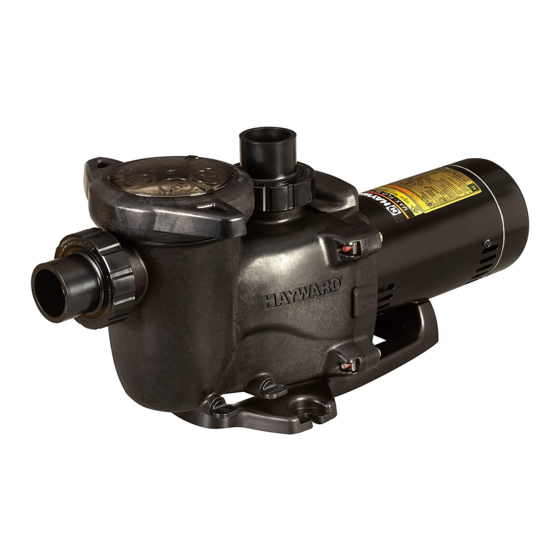
MaxFlo XL
The Hayward MaxFlo XL is a series of high technology self-priming pumps that combine
performance, dependability and value with durable construction. Designed for pools of all types
and sizes, MaxFlo XL features 1 1/2" x 2" union connections to match a variety of plumbing
configurations and a cam and ramp strainer cover that seals with less than a quarter turn. The
MaxFlo XL is an ideal choice for both new construction or as a replacement pump.
Basic safety precautions should always be followed, including the following: Failure to follow
This is the safety-alert symbol. When you see this symbol on your equipment or in this manual, look for
one of the following signal words and be alert to the potential for personal injury.
WARNING warns about hazards that could cause serious personal injury, death or major property
damage and if ignored presents a potential hazard.
CAUTION warns about hazards that will or can cause minor or moderate personal injury and/or property
damage and if ignored presents a potential hazard. It can also make consumers aware of actions that are
unpredictable and unsafe.
The NOTICE label indicates special instructions that are important but not related to hazards.
™
Owner's Manual
IMPORTANT SAFETY INSTRUCTIONS
instructions can cause severe injury and/or death.
Hayward Pool Products
620 Division Street, Elizabeth, NJ 07207
Phone: (908) 355-7995
www.hayward.com
USE ONLY HAYWARD GENUINE REPLACEMENT PARTS
Pump Series
Contents
Full Table of Contents................2
General Product Warnings..........3
Installation and Wiring...............5
Start up and Operation..............9
Shaft Seal Replacement............10
Replacement Parts.....................13
Warrantee....................................15
Registration.................................16
IS2300 Rev D
1
Advertisement
Table of Contents


Need help?
Do you have a question about the SP2305X7 and is the answer not in the manual?
Questions and answers