
Related Manuals for Hayward TriStar VS Series


Summary of Contents for Hayward TriStar VS Series
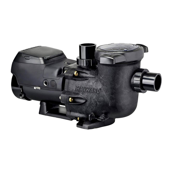
- Page 1 TriStar VS Technical Guide ® Version 1 Display Rev: 1.01 Comm Rev: 0.96 Drive Rev: 2.00.oz © 2014 Hayward Pool Products...
-
Page 2: Table Of Contents
Table of Contents Safety Precautions Page 1 Overview Page 2 Installation- Plumbing Page 3 Installation- Electrical Pages 4 - 6 Installation- Interface Pages 7 - 8 Installation- Controls Pages 9 - 17 Programming- Configuration Pages 18 - 26 Programming- Timers Pages 27 - 29 Programming- Speeds Pages 30 - 31... -
Page 3: Safety Precautions
Safety Precautions Read and follow all instructions in the owner’s manual and on the equipment. This guide does not supersede the owner’s manual. Failure to follow instructions can cause severe injury and/or death. This product should be installed and serviced only by a qualified professional. ... - Page 4 TriStar VS is available in the following two models: • TriStar VS SP3200VSP, can operate by itself in Stand-alone Mode, or be controlled from third party controls and Hayward controls that are not software compatible, by using relay contacts and/or an actuator port. SP3200VSP includes a control interface on the pump.
-
Page 5: Installation- Plumbing
Installation - Plumbing New Pools: When installing the TriStar VS on a new pool, care should be taken to ensure proper pipe and equipment sizing to handle the maximum flow required (fig 1). Existing Pools: When installing the TriStar VS on existing pools, care should be taken to insure the maximum flow does not exceed the capacity of the pipe and equipment* (fig 1). - Page 6 Installation – SP3200VSP Electrical Remove the two screws securing the control interface to the motor drive. (fig. 2) Disconnect the cable that connects the motor drive to the interface. (fig. 3) Loosen the three screws securing the interface mounting plate to the motor drive and remove the interface mounting plate to gain access to the drive wiring compartment.
- Page 7 Installation – SP3200VSPND Electrical 1. Remove the screw securing the wiring compartment cover. (fig. 6 & 7) Figure 6 Figure 7 Page 5...
-
Page 8: Installation- Electrical
Installation – Electrical Internal wiring locations (fig. 8) Dip Switches for Pump Wire connections Wiring plug for wall Address (SP3200VSPND for incoming line mounted interface model only) voltage (230v) (SP3200VSP model only) Ground Wire Terminal Figure 8 Controller External Speed Bonding wiring for Control connections... -
Page 9: Installation- Interface
Installation–Interface removal/positioning The interface assembly on model SP3200VSP can be configured in four different positions. Remove the two screws as shown (fig 9). Remove the interface assembly as shown (fig10). Reposition interface assembly as shown and re- (fig 11, 12, 13) secure with the two screws (fig Figure 10... - Page 10 Installation–Interface /Wall mount SP3200VSP Models only A wall mount kit (SPX3400DRKIT) can be used to remotely mount the interface. The kit includes a blank cover, mounting bracket, and new terminal block for connecting to the interface assembly. Maximum 500’ for data cable used for wall mount or control connection. Remove the interface assembly , interface mounting plate, and cable (Page 8).
- Page 11 (Compatible software shown below) Note: When connecting high voltage for a TriStar VS that is data connected to a Hayward/Goldline control, voltage needs to come directly from a breaker in the control, or in the case of an OnCommand, directly from the main or sub-panel and not from the filter pump relay.
- Page 12 Installation-Hayward/Goldline Controls SP3200VSPND Models only (Compatible software shown below) Software versions necessary to operate the TriStar VSP SP3200VSPND Aqua Logic/Pro Logic/Aqua Plus v2.65 or higher OnCommand 1.00 or higher E-Command 4 (Original E-Command not compatible) v2.80 or higher The pump address must be set using the SW200 DIP switch on the drive PCB.
- Page 13 Installation–Valve Actuator Ports (Jandy AquaLink to TriStar VS with Interface) Port locations on Jandy AquaLink. Note: The photo to the left is one of the most common AquaLink in the field. Older or newer units may have the AC Actuator ports in a DC Relay different position on ports (do...
- Page 14 Installation–Valve Actuator Ports (Jandy AquaLink) Shown below, on the Jandy AquaLink, are the cleaner and solar sockets with plugs installed. These sockets in many installations are not being used and would be open. Speeds are set in the TriStar VS timers menu, times are set in the controller. (All work performed must be done with power disconnected to the controller and pump) Note: Use the two outside wires of the actuator For this illustration, Actuator...
- Page 15 Installation–Valve Actuator Ports (Jandy AquaLink) If an open actuator port is not available, or more than 4 speeds is needed, one of the existing ports being used can be piggybacked in some situations. The wiring for this tie-in is shown below. Care needs to be taken to ensure that the speed being used corresponds with the use of the actuator, since both will be activated simultaneously .
- Page 16 Installation–Relay Connected Controls (Non Hayward/Goldline third party controls) Pump power (230 VAC) needs to be brought into the “line in” contacts on the Filter Pump Relay from a breaker in the control box. The “load out” side will feed the incoming high voltage for the pump.
- Page 17 Installation–Relay Connected Controls (Non Hayward/Goldline third party controls) 2. DC voltage from RS485 needs to be brought into the “line in” contacts on the Aux Relays being used. Load out from the Aux Relays will go to Step 1, 2 , or 3 as needed. “COM” on RS485 connects to “ICOM”...
- Page 18 Installation–Relay Connected Controls (Non Hayward/Goldline compatible software & third party controls) 3. The number of speeds available depends on the number of aux relays used. • Filter pump relay plus 1 auxiliary relay allows control of 2 speeds. • Filter pump relay plus 2 auxiliary relays allows control of 4 speeds.
- Page 19 Installation–Remote Stop Switch Wire the remote stop switch to terminals “OVRD” and “ICOM” on Digital Input block of pump. Note: The emergency switch needs to be a latching style that is normally open (NO). Some switches have wiring for both NO and NC (normally Closed). Refer to the e-switch for its internal wiring. When the switch is pressed the 24v circuit is completed and the pump will shut down operation.
- Page 20 Programming – User Interface PRESET SPEEDS CHECK SYSTEM LED 4 buttons that can be Display Screen programmed to run at a LED will illuminate pre-determined speed for solid when there is an a certain length of time. error condition. LED illuminates when favorite speed is selected.
- Page 21 Programming When power is supplied to the pump, the pump model will display, then the following screens (fig 24 Timer 1 will have default setting of 1750 & 25). 7 days a week from 12:00 am – 11:45 (50%), Since timer 1 has a factory default setting the pump will come on and run until the timer is changed or set as off.
-
Page 22: Programming-Configuration
Programming-Configuration On the next screen you will be asked to press the button to enter the Configuration Menu (fig 27). On the next screen it will tell you how to use the & buttons to adjust, and the to go to the next item Press the button (fig 28). - Page 23 Programming-Configuration This screen allows you to change the day and time by pressing the button to access or skip by pressing the button (fig 29). You now Use the button to highlight the day, hour, minute and AM/PM. Use the &...
- Page 24 Programming-Configuration You now select the speed indicator for RPM or % of full (revolutions per minute) speed by pressing the & buttons (100% equals 3450 RPM) (fig 31 & 32). setting you select will be used throughout programming. Press the button to continue.
- Page 25 . Press the button to continue. Note: When hooked up to a Hayward/Goldline compatible software controls place the MIN and MAX settings at the lowest and highest settings respectively so as to not conflict with the setting within the controller.
- Page 26 Programming-Configuration You will now see the Prime Duration period. Press & buttons to change the duration in 30 second intervals. The default duration is 8 minutes, and can be set between 15 minutes and zero minutes . Press the button to continue. (fig 35) You will now see the Remote Control Mode screen.
- Page 27 Programming-Configuration If the pump is not being remotely controlled, you will be asked to enable or disable the Low Temp Operation (Default is Disabled) by pressing the & buttons (fig 38). Enabling this feature will turn on the TriStar VS, if stopped, to protect the drive .
- Page 28 Programming-Configuration 18. At this point you will be asked if you would like to reset to the default parameters (factory . If yes, press and confirm on the next screen. If no, press the settings ) (fig 40) button to continue (fig 41).
-
Page 29: Programming-Timers
Programming-Timers Stand alone/Hayward Stand alone: Both times and speeds need to be set. Compatible Software controller: No timer or speed settings necessary. Dip Switch needs to be set. Relay Control Only requires that speed be set as relays on controller will start and stop pump. - Page 30 Programming-Timers This screen will alternate with fig 43 on the (fig 44) previous page. This screen tells you to use the button to modify the timer setting or the button go to the next timer. This screen allows you to rename Timer 1 to match a selection including;...
- Page 31 Programming-Timers This screen will allow you to change the start and stop time for the specific timer. Start time will be blinking, press the & buttons to change. Press the button to change the stop time, also using the & buttons (fig Press the...
-
Page 32: Programming- Speeds
Programming - Speeds 1-4 Note: The timers active light is now on as the timers have been set per previous steps. Press the button until Speeds Menu appears There are four (4) Speed buttons that can be (fig 49). set. Press the button to enter Speeds Menu. - Page 33 Programming - Speeds 1-4 While in this screen you can set the speed from 600 RPM (17%) to 3450 RPM (100%) by pressing the & button Press the button to continue. (fig 52). You can now set Speed 2, 3 & 4 following the directions for Speed 1. After Speed 4 is set press the button to continue.
-
Page 34: Operation
Operation Once configuration is completed and 1 or more timers are set, the pump will begin to operate, as long as one or more of the timer settings matches the current time. If the timer setting does not match the current time, the pump will not start unless one of the speed buttons or the quick clean button is pressed. - Page 35 Operation PRESET SPEEDS CHECK SYSTEM LED Any time one of the LED will illuminate solid Display Screen speed buttons is when there is an error pressed it will go to the condition. speed and duration that was set in the Speed Setup Menu.
- Page 36 Programming Scenarios Below is one possible Stand Alone scenario. Timer 8: Pump comes on at 6 am and goes off at 5:45 am Set to run the entire timing sequence at the low speed setting. The lower the timer number the higher the priority. In other words, timer 1 will override timer 8 settings if they are set over each other.
- Page 37 Diagnostics Press the Menu button until the Diagnostic screen appears This menu provides important (fig 54). information about the performance of the pump that can be used during troubleshooting. Below are the different screens and their meaning. These are all real-time displays.
- Page 38 Troubleshooting/Fault Codes This guide will cover only those problems with the VSC and Motor. All other pump problems, including seals, gaskets, impellers, etc., along with priming problems are addressed in the owners manual. Do not attempt to remove the drive from motor, or service the motor. The EcoStar display is not compatible with the TriStar VS.
- Page 39 Motor phase lost TriStar VS is connected to This indicates interference on the comm. ground between the a GL/Hayward control. control and TriStar VS. This is caused by frequency noise emitted Control reads “Pool from the pump drive. It travels on the comm. ground and AC bridge comm”...
- Page 40 Troubleshooting/Fault Codes Code/Fault Indications Drive Error! Indicates that there are communication problems inside the motor drive, and that the motor drive may need to be replaced. Comm failed Drive Error! Indicates that the drive memory has been damaged or corrupted and drive needs to be replaced.
Need help?
Do you have a question about the TriStar VS Series and is the answer not in the manual?
Questions and answers