
Related Manuals for Advantech AIMB-226


Summary of Contents for Advantech AIMB-226
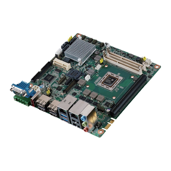
- Page 1 User Manual AIMB-226 AIMB-226 Mobile AMD R-series Quad Core/Dual Core Mini-ITX with HDMI/LVDS/DP++, 6 COM and Dual LAN...
- Page 2 No part of this manual may be reproduced, copied, translated or transmitted in any form or by any means without the prior written permission of Advantech Co., Ltd. Information provided in this manual is intended to be accurate and reliable. How- ever, Advantech Co., Ltd.
- Page 3 Whether your new Advantech equipment is destined for the labo- ratory or the factory floor, you can be assured that your product will provide the reliability and ease of operation for which the name Advantech has come to be known.
-
Page 4: Declaration Of Conformity
Caution! There is a danger of a new battery exploding if it is incorrectly installed. Do not attempt to recharge, force open, or heat the battery. Replace the battery only with the same or equivalent type recommended by the man- ufacturer. Discard used batteries according to the manufacturer's instructions. AIMB-226 User Manual... - Page 5 4JE77 D9QBJ 96SD3L-4G1333NN-AP PASS DDR3L 1333 J4208EBBG-GN-F PASS DDR3L 1333 Apacer 2XE22 D9QBJ PASS DDR3L 1600 Advantech SEC 310 XYK0 K4B2G084GD AQD-SD3L2GN16-SQ PASS DDR3L 1600 Advantech H5TC2G83EFR PBA AQD-SD3L2GN16-HQ PASS DDR3L 1600 SEC 437 BYK0 K4B2G0846Q PASS DDR3L 1600 4JE77 D9QBJ...
-
Page 6: Ordering Information
Because of Advantech’s high quality-control standards and rigorous testing, most of our customers never need to use our repair service. If an Advantech product is defec- tive, it will be repaired or replaced at no charge during the warranty period. For out- of-warranty repairs, you will be billed according to the cost of replacement materials, service time and freight. - Page 7 It should be free of marks and scratches and in perfect working order upon receipt. As you unpack the AIMB-226, check it for signs of ship- ping damage. (For example, damaged box, scratches, dents, etc.) If it is damaged or it fails to meet the specifications, notify our service department or your local sales representative immediately.
- Page 8 AIMB-226 User Manual viii...
-
Page 9: Table Of Contents
Table 1.2: Jumper Setting List........... 12 Board layout: Jumper and Connector Locations ........15 Figure 1.1 Jumper and Connector Location ......16 AIMB-226 Board Diagram ............... 16 Figure 1.2 AIMB-226 Board Diagram ........16 Safety Precautions .................. 17 Jumper Settings ..................18 1.8.1 How to Set Jumpers.............. - Page 10 Windows 7/8.1 Driver Setup ..............69 Appendix A Programming Watchdog Timer ..71 Programming the Watchdog Timer ............72 A.1.1 Watchdog Timer Overview ............72 A.1.2 Programming the Watchdog Timer..........72 Table A.1: Watchdog Timer Registers........74 AIMB-226 User Manual...
- Page 11 COM4 RI# selection pin header (JSETCOM4_V1) ......... 91 B.23 MINIPCIE, mSATA connector (MINIPCIE1)..........92 B.24 LVDS VESA, JEIDA format selection pin header (JLVDS_VCON1)..93 B.25 CMOS battery wafer box (BAT1) ............93 B.26 MINIPCIE connector (MINIPCIE2) ............94 AIMB-226 User Manual...
- Page 12 AIMB-226 User Manual...
-
Page 13: Chapter 1 General Information
Chapter General Information... -
Page 14: Introduction
Introduction AIMB-226 is a Mini-ITX motherboard based on the AMD Bald Eagle Quad core/Dual core processors, resulting in 20% compute performance improvement over AMD G- Series APU when running multiple industry-standard graphics-intensive benchmark (good graphics performance), designed with rich I/O functions and dual display sup- port, AIMB-226 is ideal for any rugged applications such as Digital Surveillance, Digi- tal Signage, Thin Client, Electronic Gaming Machines, etc. -
Page 15: Ethernet Interface
1.3.11 Environment Temperature: – 0 ~ 60° C (32 ~ 140° F), Operating – -40 ~ 85° C (-40 ~ 185° F), Non-operating 1.3.12 Physical Characteristics Dimensions: 170 mm x 170 mm (6.69" x 6.69") AIMB-226 User Manual... -
Page 16: Jumpers And Connectors
Jumpers and Connectors Connectors on the AIMB-226 motherboard link it to external devices such as hard disk drives and a keyboard. In addition, the board has a number of jumpers used to configure your system for your application. The tables below list the function of each of the board jumpers and connectors. Later sections in this chapter give instructions on setting jumpers. - Page 17 COM3 ~ COM6 box header COM3456 LVDS VESA, JEIDA format selection pin header JLVDS_VCON1 CMOS battery wafer box BAT1 MINIPCIE connector MINIPCIE2 Case open pin header (JCASE1) Signal CASEOP Case open selection pin header (JCASEOP_SW1) Signal CASEOP# HWM_CASEOP# CASEOP AIMB-226 User Manual...
- Page 18 LVDS Backlight inverter power connector (INV1) Signal +12V BKL EN BKL CTRL LVDS panel voltage selection (JLVDS1) Signal +12V LVDS_VDD +3.3V AIMB-226 User Manual...
- Page 19 OD0+ ED0+ OD1- ED1- OD1+ ED1+ OD2- ED2- OD2+ ED2+ OCK- ECK- OCK+ ECK+ DDC CLK DDC DAT OD3- ED3- OD3+ ED3+ LVDS ENBKL LVDS VCON Audio amplifier output pin header (JAMP1) Signal AMP_OUT-L- AMP_OUT-L+ AMP_OUT-R- AMP_OUT-R+ AIMB-226 User Manual...
- Page 20 Power Button+ HDD LED- Power Button- SPK_P3 SMB_DATA System Reset+ SPK_P4 SMB_CLK System Reset- DDR3 SO-DIMM socket (DIMMA1) Please see JEDEC STANDARD. DDR3 SO-DIMM socket (DIMMB1) Please see JEDEC STANDARD. 5VSB input connector (ATX_5VSB1) Signal +5VSB PSON# AIMB-226 User Manual...
- Page 21 CPU FAN connector (CPUFAN1) Signal +12V DETECT PWM IN COMS Mode selection (JCOMS1) Signal VBAT RTC RESET# Dual port USB2.0 pin header (USB910) Signal Signal AIMB-226 User Manual...
- Page 22 Dual port USB2.0 pin header (USB78) Signal Signal Dual port USB2.0 pin header (USB56) Signal Signal Dual port USB2.0 pin header (USB34) Signal Signal AIMB-226 User Manual...
- Page 23 Power LED and keyboard lock pin header (JFP2) Signal LED Power SPI Pin Header (SPI1_CN1) Signal +3.3V MISO SCLK MOSI AIMB-226 User Manual...
-
Page 24: Table 1.2: Jumper Setting List
COMS Mode selection JCOMS1 Watchdog timer output and OBS beep JWDT1+JOBS1 Power switch/HDD LED/SMBus/Speaker pin header JFP1 AT/ATX Mode selection PSON1 LVDS panel voltage selection JLVDS1 Case open selection pin header (JCASEOP_SW1) Function Setting Normal Close (Default) Normal Open AIMB-226 User Manual... - Page 25 Function Setting SATA4 (Default) SATA DOM PWR COM4_RI# Pin RI#/5V/12V selection (JSETCOM4_V1) Function Setting Set COM4_RI# as RI# (Default) Set COM4_RI# as 5V Set COM4_RI# as 12V COMS Mode selection (JCOMS1) Function Setting Normal (Default) Clear CMOS AIMB-226 User Manual...
- Page 26 Function Setting Watchdog Timer Output(2-3) (Default) OBS BEEP(4-5) (Default) Watchdog Timer Disable(1-2) OBS BEEP (4-5) (Default) Power switch/HDD LED/SMBus/Speaker pin header (JFP1) Function Setting JFP1(7-10) (Default) AT/ATX Mode selection (PSON1) Function Setting AT Mode ATX Mode (Default) AIMB-226 User Manual...
-
Page 27: Board Layout: Jumper And Connector Locations
LVDS panel voltage selection (JLVDS1) Function Setting Set LVDS Panel as +5V Set LVDS Panel as +3.3V (Default) Set LVDS Panel as +12V Board layout: Jumper and Connector Locations AIMB-226 User Manual... -
Page 28: Aimb-226 Board Diagram
Figure 1.1 Jumper and Connector Location AIMB-226 Board Diagram Figure 1.2 AIMB-226 Board Diagram AIMB-226 User Manual... -
Page 29: Safety Precautions
Caution! There is a danger of a new battery exploding if it is incorrectly installed. Do not attempt to recharge, force open, or heat the battery. Replace the battery only with the same or equivalent type recommended by the man- ufacturer. Discard used batteries according to the manufacturer’s instructions. AIMB-226 User Manual... -
Page 30: Jumper Settings
1.8.2 CMOS Clear (JCMOS1) The AIMB-226 motherboard contains a jumper that can erase CMOS data and reset the system BIOS information. Normally this jumper should be set with pins 1-2 closed. If you want to reset the CMOS data, set J1 to 2-3 closed for just a few sec- onds, and then move the jumper back to 1-2 closed. -
Page 31: System Memory
System Memory The AIMB-226 has two sockets for a 204-pin SODIMM. This socket can use 1.35 V or 1.25 V (optional) unbuffered double-data-rate three synchronous, low-voltage DRAM (DDR3L SDRAM). DRAM is available in capacities of 1 GB/2 GB/4 GB and 8 GB. - Page 32 AIMB-226 User Manual...
-
Page 33: Chapter 2 Connecting Peripherals
Chapter Connecting Peripherals... -
Page 34: Introduction
LAN2_USB1112, USB34, USB56, USB78, USB910) The AIMB-226 provides up to eight USB ports. The USB interface complies with USB Specification Rev. 3.0 supporting transmission rate up to 600 Mbps and is fuse pro- tected. The USB interface can be disabled in the system BIOS setup. -
Page 35: Dp1+Hdmi1, Dp2+Hdmi2 / Dp Connector (Esata1)
DP1+HDMI1, DP2+HDMI2 / DP Connector (ESATA1) The AIMB-226 includes two DP++, which can support DP outputs and convert to HDMI through DP-to-HDMI cables. Pin assignments for DP++ and HDMI are detailed in Appendix B. ESATA connector (ESATA1) AIMB-226 User Manual... -
Page 36: Serial Ports (Com1, Com2, Com3456)
3-4:+5V 5-6:+12V (DEFAULT:1-2) AIMB-226 supports six serial ports. Rear COM1 supports RS-232 only. Pin header COM2 supports RS-232 only. Box header COM4~6 supports RS-232; COM4 sup- ports 5V/12V power and COM3 RS-232/422/485 has auto flow control. These ports can connect to serial devices, like a thermal printer, or to a communication network. -
Page 37: Cpu Fan Connector (Cpufan1)
CPU Fan Connector (CPUFAN1) System Fan Connector (SYSFAN1, SYSFAN2) AIMB-226 User Manual... -
Page 38: Front Panel Connectors (Jfp1+Jfp2)
External speaker (JFP1/SPEAKER) JFP1/SPEAKER is a 4-pin connector for an external speaker. If there is no external speaker, the AIMB-226 provides an onboard buzzer as an alternative. To enable the buzzer, set pins 7 & 10 closed. AIMB-226 User Manual... -
Page 39: Power Led And Keyboard Lock Connector
Connect pins 1 & 2 to (on back plane) pins 2-3 closed pins 1-2 closed panel switch via cable jumper setting System On System Suspend Fast flashes Fast flashes Fast flashes System Off Slow flashes Audio Connector (AUDIO1) AIMB-226 User Manual... -
Page 40: Audio Amplifier Output Pin Header (Jamp1)
Audio amplifier output pin header (JAMP1) 2.11 Serial ATA Interface (SATA1, SATA2, SATA3) & SATA power Connector (SATA_PWR1) AIMB-226 features a high performance Serial ATA interface (up to 600 MB/s) which eases cabling to hard drives with long, thin cables. AIMB-226 User Manual... -
Page 41: Pci Express Slot (Pciex16_1, Gf1)
2.12 PCI Express slot (PCIEX16_1, GF1) AIMB-226 provides 1x PCI express x16 slot and 1x golden-finger PCIex1 2.13 ATX 12V/DCIN 12V Power Connector (ATX12V1/ DCIN1) This connector is for an ATX Micro-Fit power supply. The plugs from the power sup- ply are designed to fit these connectors in only one direction. -
Page 42: Spi Flash Connector (Spi_Cn1)
2.14 SPI Flash connector (SPI_CN1) The SPI flash card pin header may be used to flash BIOS if the AIMB-226 cannot power on. 2.15 LVDS Backlight Inverter Power Connector (INV1, JLVDS1) AIMB-226 User Manual... -
Page 43: Lvds Connector (Lvds1)
2.16 LVDS Connector (LVDS1) AIMB-226 User Manual... -
Page 44: General Purpose I/O Connector (Gpio1)
2.17 General purpose I/O Connector (GPIO1) 2.18 Digital Audio Connector (SPDFI1) AIMB-226 User Manual... -
Page 45: Front Headphone Connector (Fpaud1)
I/O module cable. Note! For motherboards with the optional HD Audio feature, we recommend that you connect a high-definition front panel audio module to this con- nector to take advantage of the motherboard’s high definition audio capability. AIMB-226 User Manual... -
Page 46: Full Size Mini Pci Express Slot (Minipcie1, Minipcie2)
2.20 Full Size Mini PCI Express Slot (MINIPCIE1, MINIPCIE2) The AIMB-226 provides 1 Full size Mini PCI express slot to support mSATA (MINIPCIE1) and 1 Full size Mini PCI express slot to support SIM card holder (MINIPCIE2). 2.21 Case open pin header (JCASE1) -
Page 47: Case Open Selection Pin Header (Jcaseop_Sw1)
2.22 Case open selection pin header (JCASEOP_SW1) 2.23 Watchdog timer output and OBS beep (JWDT1+JOBS1) AIMB-226 User Manual... -
Page 48: 5Vsb Input Connector (Atx_5Vsb1)
2.24 5VSB input connector (ATX_5VSB1) AIMB-226 User Manual... -
Page 49: Bios Operation
Chapter BIOS Operation... -
Page 50: Introduction
AIMB-226 setup screens. BIOS Setup The AIMB-226 Series system has AMI BIOS built in, with a CMOS SETUP utility that allows users to configure required settings or to activate certain system features. The CMOS SETUP saves the configuration in the CMOS RAM of the motherboard. -
Page 51: Main Menu
System Date using the <Arrow> keys. Enter new values through the keyboard. Press the <Tab> key or the <Arrow> keys to move between fields. The date must be entered in MM/DD/YY format. The time must be entered in HH:MM:SS format. AIMB-226 User Manual... -
Page 52: Advanced Bios Features
3.2.2 Advanced BIOS Features Select the Advanced tab from the AIMB-226 setup screen to enter the Advanced BIOS Setup screen. You can select any of the items in the left frame of the screen, to go to the sub menu for that item. You can display an Advanced BIOS Setup option by highlighting it using the <Arrow>... - Page 53 The value to be programmed in PCI Latency Timer Register. VGA Palette Snoop Enables or Disables VGA Palette Registers Snooping. PERR# Generation Enables or Disables PCI Device to Generate PERR#. SERR# Generation Enables or Disables PCI Device to Generate SERR#. AIMB-226 User Manual...
- Page 54 OS. ACPI Sleep State Select ACPI sleep state the system will enter when the SUSPEND button is pressed. Lock Legacy Resources Enables or Disables Lock of Legacy Resources. AIMB-226 User Manual...
- Page 55 To enable/disable TPM (TPM 1.2) set up in BIOS. TPM (Trusted Platform Module) is a secure key generator and key cache management component, enables protected storage of encryption keys and authentication credentials for enhanced security capabilities. TPM SUPPORT Disable/Enable TPM function. AIMB-226 User Manual...
- Page 56 3.2.2.4 S5 RTC Wake Settings Wake system with fixed time Enable or disable system wake on alarm event. AIMB-226 User Manual...
- Page 57 SVM mode This item allows you to enable or disable the CPU virtualization. C6 mode This item allows you to auto or disable C6 function. CPB mode This item allows you to auto or disable CPB. AIMB-226 User Manual...
- Page 58 3.2.2.6 IDE Configuration IDE Configuration Display SATA Port1 / SATA Port2/ SATA Port3/E-SATA/mSATA information. AIMB-226 User Manual...
- Page 59 USB mass storage device starts unit command time-out. Device power-up delay Maximum time the device will take before it properly report itself to the host con- troller. Mass Storage Devices Shows USB mass storage device information. AIMB-226 User Manual...
- Page 60 Super IO Configuration Case Open Warning This item will allow to enable/disable case open warning. Wake on Ring Disable/Enable RI wake event. Watch Dog Timer This item allows you to enable/disable the watchdog timer. AIMB-226 User Manual...
- Page 61 ACPI Shutdown Temperature Use this to set the ACPI shutdown temperature threshold. When the system reaches the shutdown temperature, it will be automatically shut down by ACPI OS to protect the system from overheating damage. AIMB-226 User Manual...
- Page 62 3.2.2.10 Serial Port Console Redirection Console Redirection This item allows users to enable or disable console redirection for Microsoft Windows Emergency Management Services (EMS). AIMB-226 User Manual...
-
Page 63: Chipset
3.2.3 Chipset GFX Configuration Details of display items. South Bridge Configuration Details of South bridge items. North Bridge Configuration Detail of North Bridge items. AIMB-226 User Manual... - Page 64 Select main display outputs when add-on cards are used. Integrated Graphics Select SOC display outputs. PSPP Policy the processor supports dynamically changing the link frequency LVDS Panel Type Select LVDS panel types of resolution. AIMB-226 User Manual...
- Page 65 Options for SATA configuration. SB USB Configuration Options for USB configuration. SB GPP Port Configuration Options for GPP configuration SB HD Azalia Configuration Options for SB azalia. PCI Express Configuration Options for PCI express configuration AIMB-226 User Manual...
- Page 66 3.2.3.3 North Bridge Configuration AIMB-226 User Manual...
-
Page 67: Boot
Select the Power-on state for Numlock. Quiet Boot If this option is set to Disabled, the BIOS display normal POST messages. If Enabled, an OEM Logo is shown instead of POST messages. Boot Option Priorities Set the system boot order. AIMB-226 User Manual... -
Page 68: Security
3.2.5 Security Select Security Setup from the AIMB-226 Setup main BIOS setup menu. All Security Setup options, such as password protection and virus protection, are described in this section. To access the sub menu for the following items, select the item and press <Enter>: Change Administrator / User Password. -
Page 69: Save & Exit
This item allows you to save the changes done so far as user defaults. Restore User Defaults This item allows you to restore the user defaults to all the options. Boot Override Boot device select can override your boot priority. AIMB-226 User Manual... - Page 70 AIMB-226 User Manual...
-
Page 71: Software Introduction & Service
Chapter Software Introduction & Service... -
Page 72: Introduction
Introduction The mission of Advantech Embedded Software Services is to "Enhance quality of life with Advantech platforms and Microsoft® Windows® embedded technology." We enable Windows® Embedded software products on Advantech platforms to more effectively support the embedded computing community. Customers are freed from the hassle of dealing with multiple vendors (hardware suppliers, system integrators, embedded OS distributors) for projects. - Page 73 System Throttling Refers to a series of methods for reducing power consump- tion in computers by lowering the clock frequency. This API allows the user to adjust the clock from 87.5% to 12.5%. AIMB-226 User Manual...
-
Page 74: Software Utility
The eSOS also provide for remote connection via Telnet server and FTP server so the administrator can attempt to rescue the system. Note: This function requires BIOS cus- tomization. AIMB-226 User Manual... -
Page 75: Chipset Software Installation Util
Chapter Chipset Software Installation Utility... -
Page 76: Before You Begin
Before You Begin To facilitate the installation of the enhanced display drivers and utility software, read the instructions in this chapter carefully. The drivers for the AIMB-226 are located on Advantech website. Updates are provided via Service Packs from Microsoft®. -
Page 77: Graphics Setup
Chapter Graphics Setup... -
Page 78: Introduction
Windows 7/8.1 Note! Before installing this driver, make sure the CSI utility has been installed in your system. See Chapter 5 for information on installing the CSI utility. Browse Advantech website and you can see the driver links. AIMB-226 User Manual... -
Page 79: Lan Configuration
Chapter LAN Configuration... -
Page 80: Introduction
Introduction The AIMB-226 has dual Gigabit Ethernet LANs via dedicated PCI Express x1 lanes (Realtek RTL8111G for LAN1&2) that offer bandwidth of up to 500 MB/sec, eliminat- ing the bottleneck of network data flow and incorporating Gigabit Ethernet at 1000 Mbps. -
Page 81: Windows 7/8.1 Driver Setup
Windows 7/8.1 Driver Setup Browse Advantech website and find the needed drivers. Select the LAN folder then navigate to the directory for your OS. AIMB-226 User Manual... - Page 82 AIMB-226 User Manual...
-
Page 83: Appendix A Programming Watchdog Timer
Appendix Programming the Watchdog Timer... -
Page 84: Programming The Watchdog Timer
Programming the Watchdog Timer The AIMB-226's watchdog timer can be used to monitor system software operation and take corrective action if the software fails to function within the programmed period. This section describes the operation of the watchdog timer and how to pro- gram it. - Page 85 Unlock NCT6776D Select register of watchdog timer Enable the function of the watchdog timer Use the function of the watchdog timer Lock NCT6776D AIMB-226 User Manual...
-
Page 86: Table A.1: Watchdog Timer Registers
Bit 5: Write 1 to generate a timeout signal immedi- ately and automatically return to 0. [default=0] Bit 4: Read status of watchdog timer, 1 means timer is “timeout”. AA (hex) ----- Write this address to I/O port 2E (hex) to lock the watchdog timer 2. AIMB-226 User Manual... -
Page 87: Example Program
Inc dx Mov al,10 Out dx,al ;----------------------------------------------------------- Dec dx ; Lock NCT6776D Mov al,0aah Out dx,al Enable watchdog timer and set 5 minutes as timeout interval ;----------------------------------------------------------- Mov dx,2eh ; Unlock NCT6776D Mov al,87h Out dx,al Out dx,al AIMB-226 User Manual... - Page 88 Enable watchdog timer to be reset by mouse ;----------------------------------------------------------- Mov dx,2eh ; Unlock NCT6776D Mov al,87h Out dx,al Out dx,al ;----------------------------------------------------------- Mov al,07h ; Select registers of watchdog timer Out dx,al Inc dx Mov al,08h Out dx,al ;----------------------------------------------------------- AIMB-226 User Manual...
- Page 89 Dec dx ; Enable the function of watchdog timer Mov al,30h Out dx,al Inc dx Mov al,01h Out dx,al ;----------------------------------------------------------- Dec dx ; Enable watchdog timer to be strobed reset by keyboard Mov al,0f7h Out dx,al Inc dx In al,dx Or al,40h Out dx,al AIMB-226 User Manual...
- Page 90 Dec dx ; Generate a time-out signal Mov al,0f7h Out dx,al ;Write 1 to bit 5 of F7 register Inc dx In al,dx Or al,20h Out dx,al ;----------------------------------------------------------- Dec dx ; Lock NCT6776D Mov al,0aah Out dx,al AIMB-226 User Manual...
-
Page 91: Appendix B I/O Pin Assignments
Appendix I/O Pin Assignments... -
Page 92: Interface (Com1/2/4/5/6)
Table B.1: RS-232 Interface (COM2345) Signal Signal COM2_DCD# COM2_DSR# COM2_SIN COM2_RTS# COM2_SOUT COM2_CTS# COM2_DTR# COM2_RI# COM3_DCD# COM3_DSR# COM3_SIN COM3_RTS# COM3_SOUT COM3_CTS# COM3_DTR# COM3_RI# COM4_DCD# COM4_DSR# COM4_SIN COM4_RTS# COM4_SOUT COM4_CTS# COM4_DTR# COM4_RI# COM5_DCD# COM5_DSR# COM5_SIN COM5_RTS# COM5_SOUT COM5_CTS# COM5_DTR# COM5_RI_V# AIMB-226 User Manual... -
Page 93: Rs-232/422/485 Interface (Com3456)
DTR#[4] RI#[4] DCD#[5] DSR#[5] RXD[5] RST#[5] TXD[5] CTS#[5] DTR#[5] RI#[5] DCD#[6] DSR#[6] RXD[6] RST#[6] Signal Signal TXD[6] CTS#[6] DTR#[6] RI#[6] SPI BIOS flash socket (SPI1) Signal Signal MOSI MISO SCLK WP# / IO2 HOLD# / IO3 +3.3V AIMB-226 User Manual... -
Page 94: System Fan1 Connector (Sysfan1)
System fan1 connector (SYSFAN1) Signal +12V DETECT PWM IN System fan2 connector (SYSFAN2) Signal +12V DETECT PWM IN USB & LAN Connector (LAN1_USB12,LAN2_USB1112) Signal Signal MDI_0+ MDI_0- MDI_1+ MDI_1- MDI_2+ MDI_2- MDI_3+ MDI_3- AIMB-226 User Manual... -
Page 95: Hd Analog Audio Interface (Audio1)
RX0- RX0+ TX0- TX0+ RX1- RX1+ TX1- TX1+ HD Analog Audio Interface (AUDIO1) Signal MIC IN LINE OUT LINE IN Serial ATA Connector (SATA1, SATA2, SATA3) Signal AIMB-226 User Manual... -
Page 96: At/Atx Mode (Pson1)
AT/ATX Mode (PSON1) Signal VCCAT +3.3V VCCATX B.10 COM1 connector (COM1) Signal DCD#[1] RXD[1] TXD[1] DTR#[1] DSR#[1] RTS#[1] CTS#[1] RI#[1] B.11 ATX 12V connector (ATX12V1) Signal +12V +12V AIMB-226 User Manual... -
Page 97: Dc Input Connector (Dcin1)
B.12 DC input connector (DCIN1) Signal +12V +12V B.13 eSATA1 connector (ESATA1) Signal AIMB-226 User Manual... -
Page 98: Stack Connector (Dp1+Hdmi1,Dp2+Hdmi2)
Signal TMDS D2+ ML0+ GND- TMDS D2- ML0- TMDS D1+ ML1+ TMDS D1- ML1- TMDS D0+ ML2+ TMDS D0- ML2- TMDS Clock+ ML3+ TMDS Clock- ML3- CONFIG1 CONFIG2 AUX CH+ AUX CH- Hot Plug Hot Plug DP_PWR AIMB-226 User Manual... -
Page 99: Low Pin Count Interface Header (Lpc1)
Low pin count interface header (LPC1) Signal Signal LPC CLK (33MHz) RESET# FRAME# +3.3V SMBus CLK SERIRQ SMBus DAT +5VSB B.16 Front panel audio pin header (FPAUD1) Signal MIC IN-L MIC IN-R FPAUD_DETECT# LINE OUT-R SENSE R1 SENSE LINE OUT-L SENSE R2 AIMB-226 User Manual... -
Page 100: Pci-Express X16 Slot (Pciex16_1)
+3.3V WAKE# PWRGD Reserved REFCLK+ TX0+ REFCLK- TX0- RX0+ Reserved RX0- DETECT# TX1+ CONFIG1 TX1- RX1+ RX1- TX2+ TX2- RX2+ RX2- TX3+ TX3- RX3+ Reserved RX3- Reserved CONFIG2 TX4+ Reserved TX4- RX4+ RX4- TX5+ TX5- RX5+ RX5- AIMB-226 User Manual... - Page 101 Reserved RX7- TX8+ Reserved TX8- RX8+ RX8- TX9+ TX9- RX9+ RX9- TX10+ TX10- RX10+ RX10- TX11+ TX11- RX11+ RX11- TX12+ TX12- RX12+ RX12- TX13+ TX13- RX13+ RX13- TX14+ TX14- RX14+ RX14- TX15+ TX15- RX15+ Reserved RX15- Reserved AIMB-226 User Manual...
-
Page 102: Sim Card Holder (Sim2)
B.18 SIM Card holder (SIM2) Signal UIM_PWR UIM_RESET UIM_CLK Reserved UIM_VPP UIM_DATA Reserved B.19 Watchdog timer output and OBS beep (JWDT1+JOBS1) Signal RESET# SIO BEEP FRP BEEP AIMB-226 User Manual... -
Page 103: Sata Power Supply Connector (Sata_Pwr1)
B.20 SATA power supply connector (SATA_PWR1) Signal +12V B.21 SATA DOM power selection pin header (JSATAPWR1) Signal DOM PWR B.22 COM4 RI# selection pin header (JSETCOM4_V1) Signal RI#_VCON RI#_VCON +12V RI#_VCON AIMB-226 User Manual... -
Page 104: Minipcie, Msata Connector (Minipcie1)
DETECT# RESET# PCIE_RX+ +3.3Vaux PCIE_RX- +1.5V SMB_CLK PCIE_TX- SMB_DATA PCIE_TX+ USB_D- USB_D+ +3.3Vaux +3.3Vaux Reserved V1.2_DETECT# LED_WLAN# Reserved Reserved Reserved +1.5V Reserved MSATA_DETECT# +3.3Vaux mSATA: Signal Signal Reserved +3.3V Reserved Reserved +1.5V Reserved Reserved Reserved Reserved Reserved AIMB-226 User Manual... -
Page 105: Lvds Vesa, Jeida Format Selection Pin Header (Jlvds_Vcon1)
SMB_CLK SMB_DATA Reserved Reserved +3.3V +3.3V Reserved Reserved Reserved Reserved Reserved Reserved +1.5V Reserved MSATA_DETECT# +3.3V B.24 LVDS VESA, JEIDA format selection pin header (JLVDS_VCON1) Signal +3.3V OPTION B.25 CMOS battery wafer box (BAT1) Signal BAT VCC AIMB-226 User Manual... -
Page 106: Minipcie Connector (Minipcie2)
Reserved +1.5V CLKREQ# UIM_PWR UIM_DATA REFCLK- UIM_CLK REFCLK+ UIM_RESET UIM_VPP Reserved Reserved Reserved DETECT# PERST# PCIE_RX- +3.3Vaux PCIE_RX+ +1.5V SMB_CLK PCIE_TX- SMB_DATA PCIE_TX+ USB_D- USB_D+ +3.3Vaux +3.3Vaux Reserved V1.2_DETECT# LED_WLAN# Reserved Reserved Reserved +1.5V Reserved Reserved +3.3Vaux AIMB-226 User Manual... - Page 107 AIMB-226 User Manual...
- Page 108 No part of this publication may be reproduced in any form or by any means, electronic, photocopying, recording or otherwise, without prior written permis- sion of the publisher. All brand and product names are trademarks or registered trademarks of their respective companies. © Advantech Co., Ltd. 2015...
Need help?
Do you have a question about the AIMB-226 and is the answer not in the manual?
Questions and answers