
Related Manuals for Advantech AIMB-288E


Summary of Contents for Advantech AIMB-288E
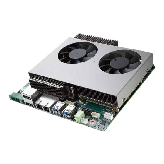
- Page 1 User Manual AIMB-288E 1U THIN Motherboard 12th Gen ® Intel Core™ Processor ® ® LGA1700 NVIDIA Quadro Embedded T1000...
- Page 2 No part of this manual may be reproduced, copied, translated, or transmitted in any form or by any means without the prior written permission of Advantech Co., Ltd. The information provided in this manual is intended to be accurate and reliable.
- Page 3 Advantech has come to be known. Your satisfaction is our primary concern. Here is a guide to Advantech’s customer services.
- Page 4 Alder Lake 2P+2E/4T SRL6Q G6900TE Alder Lake 2P+2E/2T SRL6P Memory Compatibility Category Speed Capacity Vendor Chip P/N ADVANTECH P/N SQR- DDR5 4800 32 GB Advantech IVA45 D8BNJ SD5N32G4K8MNAB SQR- DDR5 4800 16 GB Advantech 2AA45 D8BNJ SD5N16G4K8MNAB AIMB-288E User Manual...
- Page 5 * ( ) is not populated when MP. Initial Inspection Before you begin installing your motherboard, please make sure that the following materials have been shipped: 1 x AIMB-288E Intel® LGA1700 Core™ i9/i7/i5/i3 THIN AI motherboard 1 x SATA HDD cable ...
- Page 6 It should be free of marks and scratches and in perfect working order upon receipt. As you unpack the AIMB-288E, check it for signs of ship- ping damage. (For example, damaged box, scratches, dents, etc.) If it is damaged or it fails to meet the specifications, notify our service department or your local sales representative immediately.
-
Page 7: Table Of Contents
Board Layout: Jumper and Connector Locations........5 Figure 1.1 Jumper and Connector Locations (Top Side)..... 5 Figure 1.2 Jumper and Connector Locations (Bottom Side)..5 AIMB-288E Board Diagram............... 6 Figure 1.3 AIMB-288E Board Diagram ........6 Safety Precautions ..................6 Jumper Settings ..................7 1.8.1 How to Set Jumpers.............. - Page 8 VGA Setup ......... 79 Introduction ..................... 80 Windows 10 T1000 Driver Installation ............ 80 Chapter LAN Configuration ......81 Introduction ..................... 82 Features....................82 Installation....................82 Windows® 10 Driver Setup (Intel® i219LM & Intel® i226V) ....83 AIMB-288E User Manual viii...
-
Page 9: Chapter 1 General Introduction
Chapter General Introduction... -
Page 10: Introduction
Introduction AIMB-288E is designed with the Intel® H610E PCH and NVIDIA Quadro GPU to accelerate edge AI deployment. The motherboard supports Intel® desktop Corei9/i7/ i5/i3/Pentium®/Celeron® processors, up to 30 MB SmartCache, and 2 x DDR5 4800MHz SODIMM, up to 64 GB in two 262-pin SODIMM sockets. Multiple I/O con- nectivity of 2 x serial ports, 6 x USB 3.2 (Gen1), 2 x GbE LAN, 1 x SATA III, 1 x M.2 B-... -
Page 11: Ethernet Lan
Typical: 104 W; Turbo: 135 W (CPU+T000 GPU). Measure the maximum current value which system under maximum load (CPU: Top speed, RAM & Graphics: Full loading). Board size: 170 mm x 190 mm (6.69" x 7.48"). Board weight: 0.365 kg. AIMB-288E User Manual... -
Page 12: Jumpers And Connectors
Jumpers and Connectors Connectors on the AIMB-288E motherboard link it to devices such as hard disk drives and a keyboard. In addition, the board has a number of jumpers used to con- figure the system for your application. The tables below list the function of each of the board jumpers and connectors. Later sections in this chapter give instructions on setting jumpers. -
Page 13: Board Layout: Jumper And Connector Locations
Board Layout: Jumper and Connector Locations Figure 1.1 Jumper and Connector Locations (Top Side) Figure 1.2 Jumper and Connector Locations (Bottom Side) AIMB-288E User Manual... -
Page 14: Aimb-288E Board Diagram
AIMB-288E Board Diagram Figure 1.3 AIMB-288E Board Diagram Safety Precautions Warning! Always completely disconnect the power cord from the chassis when- ever you work with the hardware. Do not make connections while the power is on. Sensitive electronic components can be damaged by sud- den power surges. -
Page 15: Jumper Settings
1.8.2 Clear CMOS (JCMOS1) The AIMB-288E motherboard contains a jumper that can erase CMOS data and reset the system BIOS information. Normally this jumper should be set with pins 1-2 closed. If you want to reset the CMOS data, set CMOS1 to 2-3 closed for just a few seconds, and then move the jumper back to 1-2 closed. -
Page 16: Watchdog Timer Output And Obs Beep (Jwdt1+Jobs1)
Function Jumper Setting AT Mode ATX Mode (Default) 1.8.5 eDP Panel Voltage Selection (JLVDS1) Table 1.5: eDP Panel Voltage Selection (JLVDS1) Function Jumper Setting Jumper position for +3.3V (Default) Jumper position for +5V Jumper position for +12V AIMB-288E User Manual... -
Page 17: Com1 Ri# Pin Ri# / 5V/12V Select (Jsetcom1_V1)
4 GB, 8 GB, 16 GB, and 32 GB. The sockets can take any com- bination with SODIMMs of any size, giving a total memory size between 4 GB, 8 GB, 16 GB, and up to a max of 64 GB. AIMB-288E does NOT support error checking and correction (ECC). -
Page 18: Processor Installation
1.12 Processor Installation The AIMB-288E is designed to support 12th Gen Intel® LGA1700, Core™ i9/Core™ i7/ Core™ i5/Core™ i3, Pentium®, Celeron® processors. AIMB-288E User Manual... -
Page 19: Chapter 2 Connecting Peripherals
Chapter Connecting Peripherals... -
Page 20: Introduction
DC Input Connector (DCIN1) Signal 19V ~ 24V 19V ~ 24V DisplayPort Connector #1 / #2 (DP12) Signal Signal DP_AUX_E# AUX+ AUX- +3.3V AIMB-288E User Manual... -
Page 21: Lan1/2 (Rj-45)
LAN1/2 (RJ-45) Signal MDI0+ MDI0- MDI1+ MDI2+ MDI2- MDI1- MDI3+ MDI3- USB 3.1 Gen1 1/2/3/4 (USB12/34) Signal Signal VBUS VBUS RX1- RX2- RX1+ RX2+ TX1- TX2- TX1+ TX2+ AIMB-288E User Manual... -
Page 22: Hd Audio Interface (Line-Out) (Audio1)
Signal VBUS VBUS RX1- RX2- RX1+ RX2+ TX1- TX2- TX1+ TX2+ HD Audio Interface (Line-Out) (Audio1) Signal LINE OUT - L LINE OUT - R Front Panel Audio Header (JFPAUD1) Signal Signal MIC-L MIC-R AGND Jack Detect AIMB-288E User Manual... -
Page 23: Amplifier Connector (Amp1)
Amplifier Connector (AMP1) Signal USB 3.1 Gen1 5/6 (USB56) Signal Signal VBUS RX1- RX1+ TX2+ TX1- TX2- TX1+ RX2+ RX2- VBUS 2.10 Serial ATA Interface Connector #1 (SATA1) Signal AIMB-288E User Manual... -
Page 24: Serial Ata Interface Power Connector (Satapwr1)
Serial ATA Interface Power Connector (SATAPWR1) Signal +12V 2.12 Embedded DisplayPort Connector (EDP1) Signal Signal TX0- TX3- TX0+ TX3+ TX1- TX1+ AUX- AUX+ TX2- TX2+ +VDD_EDP +VDD_EDP 2.13 EDP Backlight Inverter Power Connector (INV1) Signal +V12 Enable backlight Brightness control AIMB-288E User Manual... -
Page 25: Ngff M.2 M-Key Connector For 2280 Module (M2M1)
+3.3V PCIE_TX+ +3.3V +3.3V PCIE_RX- +3.3V PCIE_RX+ PCIE_TX- PCIE_TX+ PCIE_RX- PCIE_RX+ PCIE_TX- PCIE_TX+ DEVSLP PCIE_RX0- / SATA_RX+ PCIE_RX0+ / SATA_RX- PCIE_TX0- / SATA_TX- PCIE_TX0+ / SATA_TX+ PLTRST# CLKREQ# PCIE_CLK- PCIEWAKE# PCIE_CLK+ SUSCLK SATA/PCIE DETECT +3.3V +3.3V +3.3V AIMB-288E User Manual... -
Page 26: Ngff M.2 E-Key Connector For 3042 Module (M2B1)
NGFF M.2 E-Key Connector for 3042 Module (M2B1) Signal Signal CFG3 +3.3V +3.3V FULL_CARD_OFF# USB_D+ W_DISABLE1# USB_D- LED1# CFG0 WAKE_WWAN# W_DISABLE2# USB3_RX- UIM_RESET USB3_RX+ UIM_CLK UIM_DATA USB3_TX- UIM_PWR USB3_TX+ DEVSLP PCIERX- / SATARX+ PCIERX+/SATARX- PCIE_CLK- PCIE_CLK+ PLTRST# AIMB-288E User Manual... -
Page 27: Mxm Connector (Mxm1)
CLKREQ# PCIE_CLKREQ# PCIE_WAKE# PCIE_WAKE# LAA_TXEN WLAN_TXEN SIMDET RESET# SUSCLK CFG1 +3.3V +3.3V +3.3V CFG2 2.16 MXM Connector (MXM1) Signal Signal +12V +12V PRESENT# PCIE_WAKE# MXM_PWRGD MXM_PWR_LEVEL MXM_TH_OVERT# MXM_TH_ALERT# SMB_DAT SMB_CLK AIMB-288E User Manual... - Page 28 PCIE_TX5- PCIE_RX5- PCIE_TX5+ PCIE_RX5+ PCIE_TX6- PCIE_RX6- PCIE_TX6+ PCIE_RX6+ PCIE_TX7- PCIE_RX7- PCIE_TX7+ PCIE_RX7+ PCIE_TX8- PCIE_RX8- PCIE_TX8+ PCIE_RX8+ PCIE_TX9- PCIE_RX9- PCIE_TX9+ PCIE_RX9+ PCIE_TX10- PCIE_RX10- PCIE_TX10+ PCIE_RX10+ PCIE_TX11- PCIE_RX11- PCIE_TX11+ PCIE_RX11+ PCIE_TX12- PCIE_RX12- PCIE_TX12+ PCIE_RX12+ PCIE_TX13- PCIE_RX13- PCIE_TX13+ PCIE_RX13+ PCIE_TX14- AIMB-288E User Manual...
- Page 29 PCIE_RX14- PCIE_TX14+ PCIE_RX14+ PCIE_TX15- PCIE_RX15- PCIE_TX15+ PCIE_RX15+ MXM_CLKREQ# PCIE_CLK- MXM_RST# PCIE_CLK+ AIMB-288E User Manual...
-
Page 30: Com Port Pin Header #1/#2 (Com12)
+3.3V +3.3V +3.3V +3.3V MXM_PRSNT# 2.17 COM Port Pin Header #1/#2 (COM12) Signal Signal COM1_DCD# COM1_DSR# COM1_SIN COM1_RTS# COM1_SOUT COM1_CTS# COM1_DDTR# COM1_RI# COM2_DCD# COM2_DSR# COM2_SIN COM2_RTS# COM2_SOUT COM2_CTS# COM2_DDTR# COM2_RI# AIMB-288E User Manual... -
Page 31: Ddr5 Sodimm Socket A1 / B1 (Dimma1/B1)
2.18 DDR5 SODIMM Socket A1 / B1 (DIMMA1/B1) Please see JEDEC STANDARD 2.19 CPU FAN Connector (CPUFAN1) Signal FAN SPEED 2.20 System Fan #1 Connector / System Fan #2 Connector (SYSFAN1/2) Signal FAN SPEED AIMB-288E User Manual... -
Page 32: Sim Card Socket (Sim1)
2.21 SIM Card Socket (SIM1) Signal UIM_PWR UIM_RESET UIM_CLK UIM_VPP UIM_DATA SIM_DET 2.22 LED Port 80 Connector (LED_P80) Signal LED_A LED_B LED_C LED_D LED_E LED_F LED_G DGH0# DGL0# AIMB-288E User Manual... -
Page 33: Voltage Selection For Edp1 Connector (Jedp1)
+V3.3 2.24 CMOS Battery Connector (BAT1) Signal +VBAT 2.25 RTC Reset Pin Header (JCMOS1) Signal N.C. RTC RESET# 2.26 PWRBTN# / RESET# / HDD LED / SM bus (JFP1) Signal Signal HDD_LED+ PWRBTN# HDD_LED- SMB_DAT SYS_RESET# SMB_CLK AIMB-288E User Manual... -
Page 34: Power Led Pin Header (Jfp2)
2.27 Power LED Pin Header (JFP2) Signal PWR_LED+ N.C. PWR_LED- 2.28 AT/ATX Mode Selection (PSON1) Signal VCCAT +3.3V VCCATX AIMB-288E User Manual... -
Page 35: Bios Operation
Chapter BIOS Operation... -
Page 36: Introduction
AIMB-286 setup screens. BIOS Setup The AIMB-288E Series system has AMI BIOS built in, with a CMOS SETUP utility that allows users to configure required settings or to activate certain system features. The CMOS SETUP saves the configuration in the CMOS RAM of the motherboard. -
Page 37: Main Menu
System Date using the <Arrow> keys. Enter new values via the keyboard. Press the <Tab> or <Arrow> keys to move between fields. The date must be entered in MM/DD/YY format. The time must be entered in HH:MM:SS format. AIMB-288E User Manual... -
Page 38: Advanced Bios Features
3.2.2 Advanced BIOS Features Select the Advanced tab from the AIMB-288E setup menu to enter the Advanced BIOS setup page. Users can select any item in the left frame of the screen, such as CPU configuration. Select an Advanced BIOS setup option by highlighting the text using the <Arrow>... - Page 39 3.2.2.1 CPU Configuration Advanced → CPU Configuration Efficient-core Information Advanced → CPU Configuration → Efficient-core Information AIMB-288E User Manual...
- Page 40 Performance-core Information Advanced → CPU Configuration → Performance-core Information CPU SMM Enhancement Advanced → CPU SMM Enhancement AIMB-288E User Manual...
- Page 41 3.2.2.2 Power & Performance Advanced → Power & Performance CPU – Power Management Control Advanced → Power & Performance → CPU – Power Management Control AIMB-288E User Manual...
- Page 42 Current Turbo Settings Advanced → Power & Performance → CPU – Power Management Control → View/ Configure Turbo Ratio AIMB-288E User Manual...
- Page 43 Turbo Ratio Limit Options Advanced → Power & Performance → CPU – Power Management Control → View/ Configure Turbo Ratio → Turbo Ratio Limit Options AIMB-288E User Manual...
- Page 44 CPU VR Settings Advanced → Power & Performance → CPU – Power Management Control → CPU VR Settings AIMB-288E User Manual...
- Page 45 Advanced → Power & Performance → CPU – Power Management Control → CPU VR Settings → Acoustic Noise Settings Core/IA VR Settings Advanced → Power & Performance → CPU – Power Management Control → CPU VR Settings → Core/IA Settings AIMB-288E User Manual...
- Page 46 GT VR Settings Advanced → Power & Performance → CPU – Power Management Control → CPU VR Settings → GT VR Settings AIMB-288E User Manual...
- Page 47 RFI Settings Advanced → Power & Performance → CPU – Power Management Control → CPU VR Settings → RFI Settings AIMB-288E User Manual...
- Page 48 Custom P-state Table Advanced → Power & Performance → CPU – Power Management Control → Cus- tom P-state Table CPU Lock Configuration Advanced → Power & Performance → CPU – Power Management Control → CPU Lock Configuration AIMB-288E User Manual...
- Page 49 GT – Power Management Control Advanced → Power & Performance → GT – Power Management Control 3.2.2.3 PCH-FW Configuration Advanced → PCH-FW Configuration AIMB-288E User Manual...
- Page 50 Firmware Update Configuration Advanced → PCH-FW Configuration → Firmware Update Configuration PTT Configuration Advanced → PCH-FW Configuration → PTT Configuration AIMB-288E User Manual...
- Page 51 FIPS Configuration Advanced → PCH-FW Configuration → FIPS Configuration ME debug Configuration Advanced → PCH-FW Configuration → ME debug Configuration AIMB-288E User Manual...
- Page 52 SMBIOS Type 130 OEM Capabilities Advanced → PCH-FW Configuration → ME Debug Configuration → SMBIOS Type 130 OEM Capabilities Anti-Rollback SVN Configuration Advanced → PCH-FW Configuration → Anti-Rollback SVN Configuration AIMB-288E User Manual...
- Page 53 OEM Key Revocation Configuration Advanced → PCH-FW Configuration → OEM Key Revocation Configuration 3.2.2.4 Trusted Computing Settings Advanced → Trusted Computing AIMB-288E User Manual...
- Page 54 3.2.2.5 ACPI Settings Advanced → ACPI Settings 3.2.2.6 NCT6126D Super IO configuration Advanced → NCT6126D Super IO Configuration AIMB-288E User Manual...
- Page 55 Serial Port 1 Configuration Advanced → NCT6126D Super IO Configuration → Serial Port 1 Configuration Serial Port 2 Configuration Advanced → NCT6126D Super IO Configuration → Serial Port 2 Configuration AIMB-288E User Manual...
- Page 56 3.2.2.7 NCT6126D HW Monitor Advanced → NCT6126D HW Monitor Smart Fan Function Advanced → NCT6126D HW Monitor → Smart Fan Function AIMB-288E User Manual...
- Page 57 3.2.2.8 S5 RTC Wake Settings Advanced → S5 RTC Wake Settings AIMB-288E User Manual...
- Page 58 3.2.2.9 Serial Port Console Redirection Advanced → Serial Port Console Redirection Legacy Console Redirection Settings Advanced → Serial Port Console Redirection → Legacy Console Redirection Set- tings AIMB-288E User Manual...
- Page 59 3.2.2.10 USB Configuration Advanced → USB Configuration 3.2.2.11 Network Stack Configuration Advanced → Network Stack Configuration AIMB-288E User Manual...
- Page 60 3.2.2.12 NVMe Configuration Advanced → NVMe Configuration 3.2.2.13 TLS Auth Configuration Advanced → TLS Auth Configuration AIMB-288E User Manual...
- Page 61 3.2.2.14 Driver Health Advanced → Driver Health AIMB-288E User Manual...
-
Page 62: Chipset Configuration Setting
Users can display a Chipset Setup option by highlighting it using the <Arrow> keys. All Chipset Setup options are described in this section. The Chipset Setup screens are shown below. The sub- menus are described on the following pages. AIMB-288E User Manual... - Page 63 3.2.3.1 System Agent (SA) Configuration Chipset → System Agent (SA) Configuration Memory Configuration Chipset → System Agent (SA) Configuration → Memory Configuration AIMB-288E User Manual...
- Page 64 Graphics Configuration Chipset → System Agent (SA) Configuration → Graphics Configuration External Gfx Card Primary Display Configuration Chipset → System Agent (SA) Configuration → Graphics Configuration → External Gfx Card Primary Display Configuration AIMB-288E User Manual...
- Page 65 LCD Control Chipset → System Agent (SA) Configuration → Graphics Configuration → LCD Con- trol DMI/OPI Configuration Chipset → System Agent (SA) Configuration → DMI/OPI Configuration AIMB-288E User Manual...
- Page 66 DMI Advanced Menu Chipset → System Agent (SA) Configuration → DMI/OPI Configuration → DMI Advanced Menu AIMB-288E User Manual...
- Page 67 PCI Express Configuration Chipset → System Agent (SA) Configuration → PCI Express Configuration MXM 3.1 (3D) Controller Chipset → System Agent (SA) Configuration → PCI Express Configuration → MXM 3.1 (3D) Controller AIMB-288E User Manual...
- Page 68 3.2.3.2 PCH-I/O Configuration Chipset → PCH-IO Configuration AIMB-288E User Manual...
- Page 69 When ErP is enabled, restore AC power loss & the below features are not supported. [USB: S3/S4] [PCIE Wake] Connect to PCIe slots depending on add-on card driver behavior. [RTC: S5] [WOR: S5] [WOL: depends on LAN chip and driver behavior (GBE)] Supports S3/S4/S5 (with I219 & I226) AIMB-288E User Manual...
- Page 70 PCI Express Configuration Chipset → PCH-IO Configuration → PCI Express Configuration PCIe EQ Settings Chipset → PCH-IO Configuration → PCI Express Configuration → PCIe EQ Settings AIMB-288E User Manual...
- Page 71 M.2 B-Key Chipset → PCH-IO Configuration → PCI Express Configuration → M.2 B-Key AIMB-288E User Manual...
- Page 72 RENESAS (PCIE to USB) Chipset → PCH-IO Configuration → PCI Express Configuration → RENESAS (PCIE to USB) AIMB-288E User Manual...
- Page 73 LAN2 Chipset → PCH-IO Configuration → PCI Express Configuration → LAN2 AIMB-288E User Manual...
- Page 74 M.2 M-Key Chipset → PCH-IO Configuration → PCI Express Configuration → M.2 M-Key AIMB-288E User Manual...
- Page 75 SATA Configuration Chipset → PCH-IO Configuration → SATA Configuration AIMB-288E User Manual...
- Page 76 Security Configuration Chipset → PCH-IO Configuration → Security Configuration HD Audio Subsystem Configuration Settings Chipset → PCH-IO Configuration→ HD Audio Subsystem Configuration Settings AIMB-288E User Manual...
-
Page 77: Security
Select this option and press <ENTER> to access the sub-menu, and then type in the password. Set the administrator password. User Password Select this option and press <ENTER> to access the sub-menu, and then type in the password. Set the user password. AIMB-288E User Manual... -
Page 78: Boot Settings
Secure Boot Security → Secure Boot 3.2.5 Boot Settings AIMB-288E User Manual... -
Page 79: Save & Exit Configuration
1. Select Discard Changes and Exit from the Save & Exit menu and press <Enter>. The following message appears: Discard Changes and Exit Setup now? [Ok] or [Cancel] 2. Select Ok to discard changes and exit. Save Changes and Reset AIMB-288E User Manual... - Page 80 Select Restore Defaults from the Exit menu and press <Enter>. Save as User Default Saves all current settings as a user default. Restore User Default Restores all settings to user default values. Boot Override Shows the boot device types on the system. AIMB-288E User Manual...
-
Page 81: Software Introduction & Service
Chapter Software Introduction & Service... -
Page 82: Introduction
Introduction The mission of Advantech Embedded Software Services is to "Enhance quality of life with Advantech platforms and Microsoft® Windows® embedded technology." We enable Windows® Embedded software products on Advantech platforms to more effectively support the embedded computing community. Customers are freed from the hassle of dealing with multiple vendors (hardware suppliers, system integrators, embedded OS distributors) for projects. - Page 83 System Throttling System throttling refers to a series of methods for reducing power consumption in computers by lowering the clock fre- quency. This API allows the user to adjust the clock from 87.5% to 12.5%. AIMB-288E User Manual...
-
Page 84: Software Utility
Monitoring is a utility for customers to monitor aspects of system health like voltage, CPU and system temperature, and fan speed. These items are important to a device. If critical errors occur and are not solved immediately, per- manent damage may be caused. AIMB-288E User Manual... -
Page 85: Chipset Software Installation Utility
Chapter Chipset Software Installation Utility... -
Page 86: Before You Begin
Before You Begin To facilitate the installation of the enhanced display drivers and utility software, read the instructions in this chapter carefully. The drivers for the AIMB-288E are located on the Advantech support website: http://support.advantech.com/support. The driv- ers on the support website will guide and link you to the utilities and drivers under a Windows system. -
Page 87: Vga Setup
Chapter VGA Setup... -
Page 88: Introduction
Introduction The AIMB-288E is embedded with an integrated Nvidia T1000 MXM GPU card. You need to install the T1000 driver to enable the function. Optimized integrated graphics solution: the Intel® Flexible Display Interface supports versatile display options and a 32-bit 3D graphics engine. Dual independent displays... -
Page 89: Lan Configuration
Chapter LAN Configuration... -
Page 90: Introduction
Introduction The AIMB-288E has two Gigabit Ethernet LANs via dedicated PCI Express x1 lanes, Intel® i226V and I219LM (Phy), that offer bandwidth of up to 500 MB/sec, eliminating the bottleneck of network data flow and incorporating Gigabit Ethernet at 1000 Mbps. -
Page 91: Windows® 10 Driver Setup (Intel® I219Lm & Intel® I226V)
Select “Autorun”, then navigate to the directory for your OS. Note! Before installing this driver, make sure the CSI utility has been installed in your system. See Chapter 5 for information on installing the CSI util- ity. AIMB-288E User Manual... - Page 92 No part of this publication may be reproduced in any form or by any means, electronic, photocopying, recording or otherwise, without prior written permis- sion from the publisher. All brand and product names are trademarks or registered trademarks of their respective companies. ©Advantech Co., Ltd. 2023...
Need help?
Do you have a question about the AIMB-288E and is the answer not in the manual?
Questions and answers