
Related Manuals for Advantech AIMB-230


Summary of Contents for Advantech AIMB-230
- Page 1 User Manual AIMB-230 Intel® Core™ i5-4300U/ Celeron 2980U Mini-ITX with eDP/DP/ DP++, 2 COM, and Dual LAN...
- Page 2 The documentation and the software included with this product are copyrighted 2015 by Advantech Co., Ltd. All rights are reserved. Advantech Co., Ltd. reserves the right to make improvements in the products described in this manual at any time without notice.
- Page 3 Our dealers are well trained and ready to give you the support you need to get the most from your Advantech products. In fact, most problems reported are minor and are able to be easily solved over the phone.
-
Page 4: Declaration Of Conformity
Caution! There is a danger of a new battery exploding if it is incorrectly installed. Do not attempt to recharge, force open, or heat the battery. Replace the battery only with the same or equivalent type recommended by the man- ufacturer. Discard used batteries according to the manufacturer's instructions. AIMB-230 User Manual... -
Page 5: Ordering Information
1 x mSATA 2 x USB2.0 PCIe AIMB-230G2-U0A1E Celeron LVDS/eDP (optional) Order Number Display GbE COM USB Audio Remark AIMB-B12305-00Y1E i5 DP/HDMI, 4 x USB3.0 Line Out Barebone, with DP++/DVI/ 2 x USB2.0 Mic-In thermal module AIMB-B12300-00Y1E Celeron HDMI AIMB-230 User Manual... - Page 6 Because of Advantech’s high quality-control standards and rigorous testing, most of our customers never need to use our repair service. If an Advantech product is defec- tive, it will be repaired or replaced at no charge during the warranty period. For out- of-warranty repairs, you will be billed according to the cost of replacement materials, service time and freight.
- Page 7 It should be free of marks and scratches and in perfect working order upon receipt. As you unpack the AIMB-230, check it for signs of ship- ping damage. (For example, damaged box, scratches, dents, etc.) If it is damaged or it fails to meet the specifications, notify our service department or your local sales representative immediately.
- Page 8 AIMB-230 User Manual viii...
-
Page 9: Table Of Contents
Table 1.2: Connectors ..............4 Board layout: Jumper and Connector Locations ........6 Figure 1.1 Jumper and Connector Location ........ 6 AIMB-230 Board Diagram ................. 7 Figure 1.2 AIMB-230 Board Diagram .......... 7 Safety Precautions ..................8 Jumper Settings ..................8 1.8.1 How to Set Jumpers.............. - Page 10 LAN Configuration ......67 Introduction ..................... 68 Features....................68 Installation....................68 Windows® 7 Driver Setup (Realtek RTL8111E) ........69 Appendix A I/O Pin Assignments ......71 USB Header (USB56) ................72 Table A.1: USB Header (USB56) ..........72 AIMB-230 User Manual...
- Page 11 (COM1_S1~S4) ............82 A.27 Watch dog and Open chassis alarm (JWDT1+JOBS1) ......82 Table A.26:Watchdog and Open Chassis Alarm (JWDT1+JOBS1) .................. 82 A.28 Low Pin Count Bus (LPC1) ..............83 Table A.27:Low Pin Count Bus (LPC1)........83 AIMB-230 User Manual...
- Page 12 AIMB-230 User Manual...
-
Page 13: Chapter 1 General Information
Chapter General Information... -
Page 14: Introduction
Introduction AIMB-230 is designed with the Intel® HASWELL ULT Dual Core for industrial appli- cations that require both performance computing and enhanced power management capabilities. The motherboard supports Intel HASWELL ULT Dual Core i5 1.9 GHz / Celeron 1.6GHz processor up to 3 MB L3 cache and DDR3L SO-DIMM 1600 up to 16GB. -
Page 15: Graphics
Power consumption: TBD Measure the maximum current value which system under maximum load (CPU: Top speed, RAM & Graphic: Full loading) Board size: 170 mm x 170 mm (6.69" x 6.69") Board weight: 0.365 kg AIMB-230 User Manual... -
Page 16: Jumpers And Connectors
Jumpers and Connectors Connectors on the AIMB-230 motherboard link it to devices such as hard disk drives and a keyboard. In addition, the board has a number of jumpers used to configure your system for your application. The tables below list the function of each of the board jumpers and connectors. Later sections in this chapter give instructions on setting jumpers. - Page 17 LAN1 status connector AMPJ1 Amplifier connector EDP1 eDP connector DP-HDMI1 Display port and HDMI connector Display Port connector MINI_PCIE1 Full-sized Mini PCI Express x 1 slot / mSATA X 1 Slot MINI_PCIE2 Half-sized Mini PCI Express x 1 AIMB-230 User Manual...
-
Page 18: Board Layout: Jumper And Connector Locations
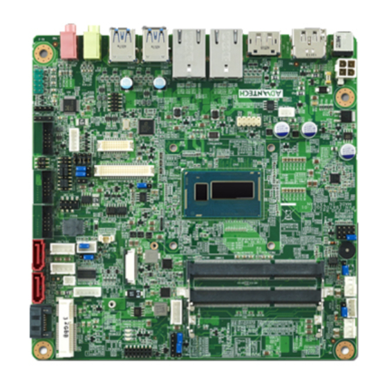
COM2 COM1 VCON1 JLVDS1 & JLVDS2 JESTCOM1 JVBR1 JCOM1 LVDS1 COM1_S1 ~ COM1_S4 USB56 EDP1 INV1 SPDIF_O1 ATX_5V1 AMPJ1 LANLED1 GPIO1 FP_AUDIO1 ATX12V1 DCIN1 DP+HDMI1 LAN1 LAN2 USB12 USB34 AUDIO1 AUDIO2 Figure 1.1 Jumper and Connector Location AIMB-230 User Manual... -
Page 19: Aimb-230 Board Diagram
(1 x USB 2.0) Co-lay mSATA (1 x mSATA) Embedded Controller EC IT8528E ALC 892/886 BIOS LPC header Infineon SLB9635 1 RS-232/485/422 COM, TPM 1.2 1 RS-232 COM, PS/2, (optional) WDT, 8bit GPIO Figure 1.2 AIMB-230 Board Diagram AIMB-230 User Manual... -
Page 20: Safety Precautions
1, 2, and 3. In this case you connect either pins 1 and 2, or 2 and 3. A pair of needle-nose pliers may be useful when set- ting jumpers. AIMB-230 User Manual... -
Page 21: Cmos Clear (Cmos1)
1.8.2 CMOS Clear (CMOS1) The AIMB-230 motherboard contains a jumper that can erase CMOS data and reset the system BIOS information. Normally this jumper should be set with pins 1-2 closed. If you want to reset the CMOS data, set CMOS1 to 2-3 closed for just a few seconds, and then move the jumper back to 1-2 closed. -
Page 22: Jvbr1: Backlight Control Selector For Lvds1
AT Mode 2-3 closed 1-2 closed 1.8.6 JWDT1+JOBS1: Watchdog Timer Output and OBS Alarm Option Table 1.7: JWDT1+JOBS1: Watchdog Timer Output and OBS Alarm Option Closed Pins Result 2-3* Watchdog Timer Output OBS_Beep 4-5* Error Beep* Default AIMB-230 User Manual... -
Page 23: System Memory
1 GB, 2 GB, 4 GB and 8 GB. The sockets can be filled in any combination with SODIMMs of any size, giving a total memory size between 1 GB, 2 GB, 4 GB and 8 GB. AIMB-230 does NOT support ECC (error checking and correc- tion). - Page 24 AIMB-230 User Manual...
-
Page 25: Chapter 2 Connecting Peripherals
Chapter Connecting Peripherals... -
Page 26: Introduction
LAN Ports and USB Ports (LAN1, LAN2, USB12, USB34, USB56) The AIMB-230 provides up to six USB ports. Four USB3.0 on the real side and two- pin header on the board. The USB interface complies with USB Specification Rev. 2.0 and Rev. 3.0 supporting transmission rate up to 625 Mbps and is fuse protected. -
Page 27: Dp/Hdmi And Dp++ Connector (Dp-Hdmi1/Dp1)
DP/HDMI and DP++ Connector (DP-HDMI1/DP1) DP-HDMI1 DP/HDMI DP++ The AIMB-230 includes DP/HDMI and DP++ interface that can drive conventional DP/HDMI and DP++ displays. DP-HDMI1 is include DP and HDMI connector. AIMB-230 User Manual... -
Page 28: Serial Ports (Com1~Com2)
Serial Ports (COM1~COM2) COM1/COM2 AIMB-230 supports two serial ports, and COM1 support RS232/485/422 function and 5V/12V select by jumper,RS-485 without H/W auto flow control function. These ports can connect to serial devices, such as a mouse or a printer, or to a com- munications network. -
Page 29: Ps/2 Keyboard And Mouse Connector (Kbms1)
6-pin wafer box connectors (KBMS1) on the motherboard provide connection to a PS/2 keyboard and a PS/2 mouse, respectively. CPU Fan Connector (CPU_FAN1) If a fan is used, this connector supports cooling fans of 500 mA (6 W) or less. AIMB-230 User Manual... -
Page 30: System Fan Connector (Sysfan1)
System FAN Connector (SYSFAN1) If a fan is used, this connector supports cooling fans of 500 mA (6 W) or less. AIMB-230 User Manual... -
Page 31: Front Panel Connectors (Jfp1/Jfp2)
External speaker (JFP2/SPEAKER) JFP2/SPEAKER is a 4-pin connector for an external speaker. If there is no external speaker, the AIMB-230 provides an onboard buzzer as an alternative. To enable the buzzer, set pins 7 & 10 as closed. AIMB-230 User Manual... -
Page 32: Power Led And Keyboard Lock Connector
Connect pins 1 & 2 to (on back plane) pins 2-3 closed pins 1-2 closed panel switch via cable jumper setting System On System Off Fast flashes Slow flashes Line Out, Mic In Connector (AUDIO1/AUDIO2) Line Out Mic In AIMB-230 User Manual... -
Page 33: Digital Audio Connector (Spdif_O1)
2.11 Serial ATA Interface (SATA1 ~ SATA3/ SATA_PWR1 ~ SATA_PWR3) AIMB-230 features a high performance Serial ATA interface (up to 300 MB/s) and Serial ATA III interface (up to 600 MB/s) which eases hard drive cabling with thin, space-saving cables. -
Page 34: Sata Power Connector(Sata_Pwr1~3)
2.12 SATA power connector(SATA_PWR1~3) 2.13 Full / Half Size Mini PCI Express Slot The AIMB-230 provides 1 Full size Mini PCI express slot (Co-lay mSATA) and 1 Half size Mini PCI express slot. AIMB-230 User Manual... -
Page 35: Front Headphone Connector (Fp_Audio1)
I/O module cable. Note! For motherboards with the optional HD Audio feature, we recommend that you connect a high-definition front panel audio module to this con- nector to take advantage of the motherboard’s high definition audio capability. AIMB-230 User Manual... -
Page 36: Atx 12V/Dcin 12V/5V Sb Input Power Connector (Atx12V1/Dcin1)
180 W. ATX_5V1 for Operation system shutdown command, if you used ATX12V1 input, you can via the connector to power shutdown sys- tem. PSON1 is for AT/ATX mode selection(PSON1) PSON1:1-2 AIMB-230 User Manual... -
Page 37: Spi Flash Connector(Spi_Cn1)
2.16 SPI Flash Connector(SPI_CN1) The SPI flash card pin header may be used to flash BIOS if the AIMB-230 cannot power on. Clean CMOS(CMOS1) Clean CMOS and reset RTC CMOS1: 1-2 Keep CMOS data* 3-4 Clean CMOS AIMB-230 User Manual... -
Page 38: Lcd Inverter Connector (Inv1)
2.17 LCD Inverter Connector (INV1) Note! Signal Description Signal Signal Description Vadj=0.75 V (Recommended: 4.7 KΩ, >1/16 W) ENBKL LCD backlight ON/OFF control signal AIMB-230 User Manual... -
Page 39: Lvds Connector (Lvds1)
2.18 LVDS Connector (LVDS1) 2.19 General Purpose I/O Connector (GPIO1) +3.3 AIMB-230 User Manual... - Page 40 AIMB-230 User Manual...
-
Page 41: Bios Operation
Chapter BIOS Operation... -
Page 42: Introduction
AIMB-230 setup screens. BIOS Setup The AIMB-230 Series system has AMI BIOS built in, with a CMOS SETUP utility that allows users to configure required settings or to activate certain system features. The CMOS SETUP saves the configuration in the CMOS RAM of the motherboard. -
Page 43: Main Menu
Date using the <Arrow> keys. Enter new values through the keyboard. Press the <Tab> key or the <Arrow> keys to move between fields. The date must be entered in MM/DD/YY format. The time must be entered in HH:MM:SS format. AIMB-230 User Manual... -
Page 44: Advanced Bios Features
3.2.2 Advanced BIOS Features Select the Advanced tab from the AIMB-230 setup screen to enter the Advanced BIOS Setup screen. You can select any of the items in the left frame of the screen, such as CPU Configuration, to go to the sub menu for that item. You can display an Advanced BIOS Setup option by highlighting it using the <Arrow>... - Page 45 This item allows users to enable or disable VGA Palette Snoop. PERR## Generation This item allows users to enable or disable PERR## Generation. SERR## Generation This item allows users to enable or disable SERR## Generation. AIMB-230 User Manual...
- Page 46 Link Training Timeout (uS) This item allows users to set the Link Training Timeout(uS) Unpopulated Links This item allows users to set the Unpopulated Links Restore PCIE Registers Enable or disable Restore PCIE Registers AIMB-230 User Manual...
-
Page 47: Acpi Settings
This item allows users to set the ACPI sleep state Lock Legacy Resources This item allows users to lock legacy devices’ resources. S3 Video Repost Enable or disable video repost Power on by Modem Disable/Enable power on modem function AIMB-230 User Manual... - Page 48 3.2.2.4 Trusted Computing Security Device Support Enable or disable BIOS support for security device. AIMB-230 User Manual...
- Page 49 3.2.2.5 S5 RTC Wake Settings Wake system with fixed time Enable or disable system wake on alarm event 3.2.2.6 CPU Configuration AIMB-230 User Manual...
- Page 50 This item allows users to enable or disable the Spin up Device. Device Sleep This item allows users to enable or disable the Device Sleep. SATA DEVSLEP idle Timeout Config This item allows users to enable or disable the SATA DEVSLEP idle Timeout Config. AIMB-230 User Manual...
- Page 51 3.2.2.8 INTEL Rapid Star Technology Intel® Rapid start technology This item allows users to enable or disable Intel rapid start technology. AIMB-230 User Manual...
- Page 52 3.2.2.9 PCH(FW) Configuration Me FW Image Re-Flash This item allows users to enable or disable Me FW image re-flash function. AIMB-230 User Manual...
- Page 53 This item allows users to set the Device reset time-out Device power-up delay This item allows users to set the Device power-up delay Generic USB Flash Disk 1100 This item allows users to set the Generic USB Flash Disk 1100 AIMB-230 User Manual...
- Page 54 This item allows users to set backlight enable polarity. Case Open This item allows users to set Case open enable polarity. Resume on Ring This item allows users to set Resume on Ring enable polarity. AIMB-230 User Manual...
- Page 55 Serial Port This item will allow users to enable or disable serial port. Change Settings This item allows users to change the serial port setting. Device Mode This item allows users to change the device mode. AIMB-230 User Manual...
- Page 56 3.2.2.13 PC Health Status 3.2.2.14 Serial Port Console Redirection Console Redirection This item allows users to enable or disable console redirection for Microsoft Windows Emergency Management Services (EMS). AIMB-230 User Manual...
-
Page 57: Chipset
PCIE Wake Enables or disables LAN1/2 wake up from sleep state. DeeSx Power Policies Enables or disables the DeeSx Power Policies. Restore AC Power Loss This item allows users to select off, on and last state. AIMB-230 User Manual... - Page 58 This item allows users to configure Mini PCI Express setting. Mini PCI Express This item allows users to enable or disable the PME SCI function. PCI Express Root Port This item allows users to configure PCI Express Root port setting. AIMB-230 User Manual...
- Page 59 USB Precondition This item allows user to enable or disable USB Precondition. XHCI Mode This item allows user to enable or disable XHCI Mode. XHCI Idle L1 Enables or disables the XHCI Idle L1. AIMB-230 User Manual...
- Page 60 3.2.3.3 PCH Azalia Configuration Azalia This item allows user to enable or disable azalea device. AIMB-230 User Manual...
- Page 61 3.2.3.4 System Agent (SA) Configuration VT-d This item allows users to enable or disable VT-d. AIMB-230 User Manual...
- Page 62 This item allows users to select DVMT total memory size. Gfx Low Power Mode This item allows users to enable or disable IGD low power mode. Panel Power Enable This item allows users to enable or disable Panel Power. AIMB-230 User Manual...
- Page 63 3.2.3.6 LCD Control Primary IGFX Boot Display Select Primary IGFX Boot Display. LVDS Panel Type Select LVDS Panel type. AIMB-230 User Manual...
-
Page 64: Boot
Set the system boot order. GateA20 Active This item allows you to select upon request or Always. Option ROM Messages Sets display mode for option ROM. INT19 Trap Response This item allows option ROMs to trap interrupt 19. AIMB-230 User Manual... -
Page 65: Security
3.2.5 Security Select Security Setup from the AIMB-230 Setup main BIOS setup menu. All Security Setup options, such as password protection and virus protection are described in this section. To access the sub menu for the following items, select the item and press<Enter>: Change Administrator / User Password. -
Page 66: Save & Exit
This item allows you to save the changes done so far as user defaults. Restore User Defaults This item allows you to restore the user defaults to all the options. Boot Override Boot device selection can override your boot priority. AIMB-230 User Manual... -
Page 67: Software Introduction & Service
Chapter Software Introduction & Service... -
Page 68: Introduction
Introduction The mission of Advantech Embedded Software Services is to "Enhance quality of life with Advantech platforms and Microsoft® Windows® embedded technology." We enable Windows® Embedded software products on Advantech platforms to more effectively support the embedded computing community. Customers are freed from the hassle of dealing with multiple vendors (hardware suppliers, system integrators, embedded OS distributors) for projects. - Page 69 System Throttling Refers to a series of methods for reducing power consump- tion in computers by lowering the clock frequency. This API allows the user to adjust the clock from 87.5% to 12.5%. AIMB-230 User Manual...
-
Page 70: Software Utility
The eSOS also provide for remote connection via Telnet server and FTP server so the administrator can attempt to rescue the system. Note: This function requires BIOS cus- tomization. AIMB-230 User Manual... -
Page 71: Chipset Software Installation Utility
Chapter Chipset Software Installation Utility... -
Page 72: Before You Begin
To facilitate the installation of the enhanced display drivers and utility software, read the instructions in this chapter carefully. The drivers for the AIMB-230 are located on the software installation CD. The driver in the folder of the driver CD will guide and link you to the utilities and drivers under a Windows system. -
Page 73: Windows 7 Driver Setup
Windows 7 Driver Setup Insert the driver CD into your system's CD-ROM drive. You can see the driver folder items. Navigate to the "Chipset" folder and click "infinst_autol.exe" to complete the installation of the driver. AIMB-230 User Manual... - Page 74 AIMB-230 User Manual...
-
Page 75: Vga Setup
Chapter VGA Setup... -
Page 76: Introduction
Insert the driver CD into your system's CD-ROM drive. You can see the driver folders items. Navigate to the "VGA" folder and click "setup.exe" to complete the installation of the drivers for Windows 7 and Windows XP. AIMB-230 User Manual... - Page 77 AIMB-230 User Manual...
- Page 78 AIMB-230 User Manual...
-
Page 79: Lan Configuration
Chapter LAN Configuration... -
Page 80: Introduction
Introduction The AIMB-230 has dual Gigabit Ethernet LANs via dedicated PCI Express x1 lanes (Realtek RTL8111E(LAN1) and RTL8111E (LAN2)) that offer bandwidth of up to 500 MB/sec, eliminating the bottleneck of network data flow and incorporating Gigabit Ethernet at 1000 Mbps. -
Page 81: Windows® 7 Driver Setup (Realtek Rtl8111E)
Windows® 7 Driver Setup (Realtek RTL8111E) Insert the driver CD into your system's CD-ROM drive. Select the LAN folder then navigate to the directory for your OS. AIMB-230 User Manual... - Page 82 AIMB-230 User Manual...
-
Page 83: Appendix A I/O Pin Assignments
Appendix I/O Pin Assignments... -
Page 84: Usb Header (Usb56)
Table A.1: USB Header (USB56) Signal Signal USB0_VCC5 USB1_VCC5 USB0_D- USB1_D- USB0_D+ USB1_D+ DP/HDMI Connector (DP-HDMI1) Table A.2: DP/HDMI Connector (DP-HDMI1) Signal Signal DP_0+ DP_3- DP_0- DP_1+ HDMI_CLK_AUX+ DP-HDMI_DATA DP_1- DP-HDMI_AUX DP_2+ DP-HPD HDMI_HPD DP_2- +V3.3 DP_3+ DP/HDMI_DET AIMB-230 User Manual... -
Page 85: A.3 Dp Connector
Table A.3: DP Connector Signal Signal DP2_0+ DP2_3- DP2_0- DP2_AUX_EN DP2_1+ DP2_AUX+ DP2_1- DP2_2+ DP2_AUX- DP2_HPD DP2_2- DP2_3+ +V3.3 SPI_CN1: SPI Fresh Card Pin Connector Table A.4: SPI_CN1:SPI Fresh Card Pin Connector Signal Signal +F1_3V F1_SPI_CS#_Q F1_SPI_CLK_Q F1_SPI_MISO_Q F1_SPI_MOSI_Q AIMB-230 User Manual... -
Page 86: A.5 Ps/2 Keyboard And Mouse Connector (Kbms1)
CPU Fan Power Connector (CPUFAN1/ CPUFAN1_1) Table A.6: CPU Fan Power Connector (CPUFAN1/CPUFAN_1) Signal CPU FAN VCC DETECT CPU PWM CPU Fan Speed Control (JCPUFAN1) Table A.7: CPU Fan Speed Control (JCPUFAN1) Signal VCC Control 2-3* PWM Control AIMB-230 User Manual... -
Page 87: A.8 System Fan Power Connector (Sys_Fan1)
You can use an LED to indicate when the single board computer is on. Pin 1 of JFP3 supplies the LED's power, and Pin 3 is the ground. Table A.10: Power LED & Keyboard Lock Connector (JFP2) Function LED power KEYLOCK# AIMB-230 User Manual... -
Page 88: A.11 Power Switch/Reset Switch/Hdd Led/Smbus/Speaker (Jfp1/Jfp2)
Speaker 4 HDD LED SMB_CLK A.12 USB/LAN Ports (LAN1/LAN2/USB12/USB34) Table A.12: USB Port Signal Signal USB3_RX+ USB2_D- USB2_D+ USB3_TX- USB3_TX+ USB3_RX- Table A.13: Ethernet 10/100/1000 Mbps RJ-45 Port Signal Signal MDI0+ MDI2- MDI0- MDI1- MDI1+ MDI3+ MDI2+ MDI3- AIMB-230 User Manual... -
Page 89: A.13 Line Out, Mic In Connector (Audio1/Audio2)
AT/ATX Mode (PSON1) Table A.15: AT/ATX Mode (PSON1) Signal Signal #PSON_SIO #PSON (to super IO) (to power supply) A.16 HD Audio Interface (FP_AUDIO1) Table A.16: AC-97 Audio Interface (FPAUD1) Signal Signal MIC2_L MIC2_R FP_AUD_DET LOUT2_R SRTN1 LOUT2_DET LOUT2_L SRTN2 AIMB-230 User Manual... -
Page 90: A.17 Gpio Pin Header (Gpio1)
Table A.17: GPIO Pin Header (GPIO1) Signal Signal GPIO0 GPIO4 GPIO1 GPIO5 GPIO2 GPIO6 GPIO3 GPIO7 A.18 LVDS Connector: LVDS1 Table A.18: LVDS Connector: LVDS1 Signal Signal VDD_LVDS VDD_LVDS VDD_LVDS VDD_LVDS LVDS_L0_N LVDS_U0_N LVDS_L0_P LVDS_U0_P LVDS_L1_N LVDS_U1_N LVDS_L1_P LVDS_U1_P AIMB-230 User Manual... -
Page 91: A.19 Lvds Power Jumper (Jlvds1/Jlvds2)
LVDS Power Jumper (JLVDS1/JLVDS2) JLVDS1 JLVDS2 3.3V Note! JLVDS1 and JLVDS2 can’t be used at the same time, or else M/B would be damaged. A.20 LVDS Inverter (INV1) Table A.19: LVDS Power Jumper Signal +12V BL_EN BL_CLT AIMB-230 User Manual... -
Page 92: A.21 Lvds Backlight Control (Jvbr1)
EC control A.22 ATX12V/12V DC IN (ATX12V1/DCIN1) ATX12V1 DCIN1 Table A.21: ATX 12 V connector (ATX12V1) Signal Signal aGND aGND CPU_+12V CPU_+12V A.23 HD Digital Audio Interface (SPDIF_O1) Table A.22: HD Digital Audio Interface (SPDIF_OUT1) Signal SPDIF Out AIMB-230 User Manual... -
Page 93: A.24 Amplifier Audio Output (Ampj1)
Signal Signal AMP_L- AMP_L+ AMP_R- AMP_R+ A.25 COM1 Protocols Selection (JSETCOM1) Table A.24: COM1 Protocol Selection (JSETCOM1) RS-232* 8-10 13-15 14-16 RS-422 9-11 10-12 15-17 16-18 RS-485 9-11 10-12 15-17 16-18 Note! Without H/W auto flow control. AIMB-230 User Manual... -
Page 94: A.26 Com1 Rs422/485 Master Or Slave Selection (Com1_S1~S4)
COM1_S3 master 1-2* slave COM1_S4 master A.27 Watch dog and Open chassis alarm (JWDT1+JOBS1) Table A.26: Watchdog and Open Chassis Alarm (JWDT1+JOBS1) Signal Signal EC_Beep Beep Reset JWDT1+JOBS1: 2-3 WDT control by EC* 4-5 Alarm by EC* AIMB-230 User Manual... -
Page 95: A.28 Low Pin Count Bus (Lpc1)
A.28 Low Pin Count Bus (LPC1) Table A.27: Low Pin Count Bus (LPC1) Signal Signal CLK24M LPC_AD1 LPC_AD2 80PORT_RST LPC1_SMB_CLK LPC_AD0 SERIRQ LPC_FRAME LPC1_SMB_DAT +3.3V +5VSB LPC_AD3 AIMB-230 User Manual... - Page 96 No part of this publication may be reproduced in any form or by any means, electronic, photocopying, recording or otherwise, without prior written permis- sion of the publisher. All brand and product names are trademarks or registered trademarks of their respective companies. © Advantech Co., Ltd. 2015...
Need help?
Do you have a question about the AIMB-230 and is the answer not in the manual?
Questions and answers