Table of Contents
Advertisement
Advertisement
Table of Contents

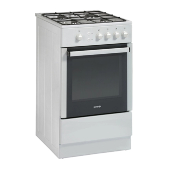
Summary of Contents for Gorenje GI 52108 A
-
Page 3: Important Precautions
Dear customer! Thank you for purchasing the appliance from our new range of gas cookers. The following information will help you understand the features of the appliance and use it safely. We hope the appliance will serve you successfully for a long period of time. IMPORTANT PRECAUTIONS ... -
Page 4: Control Panel
The manufacturer reserves the right to make minor changes in the Instructions for Use resulting from relevant technological modifications or improvements of the product. Different models are equipped with different accessories. Any additional accessories (grids, baking trays, grill pans, adjustable feet) are available in authorized GORENJE shops or our service outlets. CONTROL PANEL... -
Page 5: Oven Operation
Press the appropriate burner control knob slightly towards the appliance and turn it anti-clockwise to the „MAXIMUM POWER“ position. Then push the knob towards the panel to a limit position. Now use another hand and press the gas ignition knob on the control panel. Hold the knob pressed about 5 seconds after the flame appears to allow the flame sensor to heat up. - Page 6 A TEMPERATURE SELECTOR The gas supply to the oven burner is controlled by a temperature selector with a thermoelectric flame sensor. The power input of the oven burner as well as the temperature of the oven space can be controlled by setting the control knob to the positions 8 – 1 IGNITION OF THE OVEN BURNER ...
- Page 7 Relation between the temperature selector position and the oven temperature for different oven operations Knob position Oven temperature Kind of baked food 150 – 160° C Preservation 2 – 3 160 – 180° C Foam pastry, meringue 3 – 4 180 –...
-
Page 8: Cleaning And Maintenance
INSERTING OF GRID IN THE OVEN CLEANING AND MAINTENANCE Before attempting any cleaning or maintenance set all gas control knobs and temperature selectors to “OFF” position and let the cooker cool down completely. Keep to the following principles while cleaning or maintaining the range: ... - Page 9 OVEN procedure for cleaning of internal glass door.
-
Page 10: Bulb Replacement
BULB REPLACEMENT NOTE: Set all the control knobs to the OFF position and For oven illumination always use T 300° C, E14, 230-240V, 25W bulb. disconnect the range from the mains. Unscrew the bulb glass cover in the oven by turning Glass cover Lamp it anti-clockwise. - Page 11 INSTALLATION INSTRUCTIONS AND SETTINGS Solely company authorized to provide such activities may perform the installation of this appliance and it should be installed in compliance with local standards and regulations. All installation, servicing and maintenance work should be carried out by competent personnel, and should comply with standing regulations, standards and requirements. Installation of the appliance must be endorsed on the Certificate of Warranty.
-
Page 12: Connection To Gas Supply
CONNECTION TO GAS SUPPLY GAS SUPPLY The appliance may be connected to gas supply by only by the authorized personnel. Connection must comply with the local standards and requirements. The gas supply pipe must be fitted with the accessible gas shut-off cock, located before the coupling with the cooker. WARNING: In handling the gas line (e.g. -
Page 13: Primary Air Adjustment
HOB BURNER SETTINGS MINIMUM OUTPUT ADJUSTMENT Before starting any adjustments disconnect the appliance from the mains power supply. Adjustments must be carried out with the tap at the "SAVING" position. The minimum gas output is correctly adjusted when the inner cone of the flame arrives at the height of 3 to 4 mm. - Page 14 Thermocouple, 2. Ignition electrode, 3. Washer ADJUSTMENT OF OVEN BURNER MINIMUM POWER On completion of this operation, proceed as follows: Remove the oven bottom. Set the temperature selector control knob to position 8 and heat the oven for 15 ...
- Page 15 GRILL BURNER SETTINGS PRIMARY AIR ADJUSTMENT FLAME SENSOR ADJUSTM ENT To access the primary air adjusting screw (5), open or remove oven door and remove If the flame sensor does not operate properly, check its position according to fig. oven bottom (2). By unscrewing the adjusting screw the quantity of primary air is increase, by tightening it is reduced.
-
Page 16: Electrical Connection
ELECTRICAL CONNECTION IMPORTANT: The electrical connection must be carried out in accordance with the current standards and laws in force The wires in the mains lead on this appliance are and by a qualified electrician. coloured in accordance with the following code: Green and Yellow = Earth WARNING!! -
Page 17: Stability Chain
STABILITY CHAIN We recommend a stability chain is fitted to the cooker. The chain shown in the diagram below can be purchased from most hardware outlets and DIY shops. SECURELY ATTACH STABILITY CHAIN USING SCREW SUPPLIED Stability Hook Firmly fix chain REAR OF OVEN to rear of cooker Chain to be as... - Page 18 TECHNICAL DATA GAS COOKER GI 52108 A GI 52108 A-IE GI 52108 G Dimensions: height / width / depth (mm) Hotplates Burner input power Left front (kW) 1,00 1,00 1,00 Left rear (kW) 1,75 1,75 1,75 Right rear (kW) 2,70...
- Page 19 FICHE, REGULATION (EU) NO 65/2014 AND PRODUCT INFORMATION REGULATION (EU) NO 66/2014 Symbol Unit Value Supplier’s name or trade mark GORENJE Model identification GI52108 Energy Efficiency Index per cavity 120,5 cavity Energy efficiency class 6,69 MJ/cycle Energy consumption (gas) during a cycle in conventional mode...


Need help?
Do you have a question about the GI 52108 A and is the answer not in the manual?
Questions and answers