Imperx LYNX Series Hardware User Manual
Cameralink and gige models
Hide thumbs
Also See for LYNX Series:
- User manual (209 pages) ,
- User manual (216 pages) ,
- Software user manual (57 pages)
Table of Contents
Advertisement
Quick Links
LYNX Hardware User's Manual
LYNX
Hardware User's Manual
( CameraLink and GigE models )
HIGH-RESOLUTION, FAST, FIELD UPGRADEABLE,
PROGRAMMABLE, 8/10/12 BIT
DIGITAL CAMERAS
CONFIDENTIAL NOTICE:
These products are not intended for use in life support appliances, devices, or systems where malfunction of these
products can reasonably be expected to result in personal injury. Imperx customers using or selling these products for
use in such applications do so at their own risk and agree to fully indemnify Imperx for any damages resulting from
such improper use or sale.
Copyright © 2005, Imperx Inc. All rights reserved. All information provided in this manual is believed to be accurate
and reliable. Imperx assumes no responsibility for its use. Imperx reserves the right to make changes to this
information without notice. Redistribution of this manual in whole or in part, by any means, is prohibited without
obtaining prior permission from Imperx.
Imperx, Inc.
Rev. 11
6421 Congress Ave.
1/21/2008
Boca Raton, FL 33487
+1 (561) 989-0006
1 of 216
Advertisement
Table of Contents

Related Manuals for Imperx LYNX Series


Summary of Contents for Imperx LYNX Series
- Page 1 Imperx customers using or selling these products for use in such applications do so at their own risk and agree to fully indemnify Imperx for any damages resulting from such improper use or sale.
-
Page 2: Revision History
LYNX Hardware User’s Manual Revision History Rev. 1 12/15/05 P. Dinev Initial release. Rev. 2 1/04/06 G. Angelone Modify driver installation to select Pro1000.inf Rev. 3 1/23/06 J. Egri Updated Appendix B - LynxTerminal to reflect the addition of GigE support. Rev. -
Page 3: Table Of Contents
LYNX Hardware User’s Manual Table of Contents Chapter 1 – Introduction _______________________________________________________ 14 LYNX FAMILY ______________________________________________________ 15 GENERAL DESCRIPTION ____________________________________________ 17 LYNX TECHNICAL SPECIFICATIONS ________________________________ 19 CAMERA CONNECTIVITY ___________________________________________ 25 Camera Link Output _______________________________________________ 25 1.4.1 GigE Output ______________________________________________________ 29 1.4.2 Power Supply _____________________________________________________ 31 1.4.3... - Page 4 LYNX Hardware User’s Manual 2.4.1 Electronic Shutter__________________________________________________ 87 2.4.2 Variable Frame Rate – Programmable Integration ________________________ 87 2.4.3 Long Integration___________________________________________________ 88 EXTERNAL TRIGGER _______________________________________________ 90 Triggering Inputs __________________________________________________ 90 2.5.1 Standard Triggering - Programmable Exposure __________________________ 92 2.5.2 Fast Synchronized Triggering – Rapid Capture___________________________ 93 2.5.3 Double Exposure Triggering _________________________________________ 94 2.5.4...
- Page 5 LYNX Hardware User’s Manual Set Boot From ( ) ______________________________________________ 123 3.6.1 ‘sbf’ Get Boot From ( ) ______________________________________________ 123 3.6.2 ‘gbf’ Load From Factory ( ) ___________________________________________ 123 3.6.3 ‘lff’ Load From User ( ) _____________________________________________ 124 3.6.4 ‘lfu’ Save To Factory ( ) _____________________________________________ 124 3.6.5...
- Page 6 LYNX Hardware User’s Manual ) ___________________________________ 137 3.8.11.1 Set Noise Correction ( ‘snc’ ) ___________________________________ 137 3.8.11.2 Get Noise Correction ( ‘gnc’ Horizontal mode__________________________________________________ 138 3.8.12 ) ___________________________________ 138 3.8.12.1 Set Horizontal Mode ( ‘shm’ ) ___________________________________ 138 3.8.12.2 Get Horizontal Mode ( ‘ghm’...
- Page 7 LYNX Hardware User’s Manual Flat Field Correction ______________________________________________ 154 3.8.22 ) __________________________________ 154 3.8.22.1 Set Flatfield Correction ( ‘sfc’ )__________________________________ 154 3.8.22.2 Get Flatfield Correction ( ‘gfc’ ) ____________________________________ 154 3.8.22.3 Get Flatfield Header ( ‘gfh’ Chapter 4 – LYNX Configurator for CameraLink __________________________________ 155 Overview ___________________________________________________________ 156 Setup ______________________________________________________________ 157 Graphical User Interface______________________________________________ 159...
- Page 8 LYNX Hardware User’s Manual C.1 Overview _____________________________________________________________ 199 C.2 Using an ASCII text editor_______________________________________________ 199 C.3 Using Microsoft Excel___________________________________________________ 200 Appendix D – LYNX CameraLink Software Installation _____________________________ 201 D.1 Software Suite _________________________________________________________ 202 D.2 Software Installation from CD____________________________________________ 203 D.3 Software Upgrade from Web Site _________________________________________ 203 Appendix E –...
- Page 9 LYNX Hardware User’s Manual List of Figures Figure 1.0 - CCD Pixel Structure....................19 Figure 1.1 - Spectral response – monochrome quantum efficiency ..........20 Figure 1.2 - Spectral response – color quantum efficiency............21 Figure 1.3 - Spectral response – UV quantum efficiency ............. 21 Figure 1.4 - Camera Back Panel –...
- Page 10 LYNX Hardware User’s Manual Figure 2.1 - Single Output Mode of Operation................57 Figure 2.2 - Dual Output Mode of Operation................58 Figure 2.3 - Center columns output mode of operation ..............59 Figure 2.4 - Center Columns Output in Dual Mode of Operation ..........60 Figure 2.5 - Center Columns Output in Dual Tap Mode ..............
- Page 11 LYNX Hardware User’s Manual Figure 2.34 - Frame Rate vs. Vertical Window Size (IPX-4M15-L/G)......... 82 Figure 2.35 - Frame Rate vs. Vertical Window Size (IPX-11M5-L/G)......... 83 Figure 2.36 - Frame Rate vs. Vertical Window Size (IPX-16M3-L/G)......... 84 Figure 2.37 - Horizontal and Vertical Binning ................85 Figure 2.38 - Electronic Shutter Position..................
- Page 12 LYNX Hardware User’s Manual Figure 4.2 - Select Port dialog...................... 157 Figure 4.3 - Area of Interest Tab ....................159 Figure 4.4 - Triggering Tab......................161 Figure 4.5 - Video Amplifiers Tab....................162 Figure 4.6 - Auto Iris Tab......................163 Figure 4.7 - Exposure Tab......................
- Page 13 LYNX Hardware User’s Manual List of Tables Table 1.0 - Pixel structure for different LYNX cameras............... 20 Table 1.1 - Camera Specifications....................22 Table 1.2 - Camera Output Connector – Signal Mapping ............26 Table 1.3 - Base Camera Link bit assignment ................27 Table 1.4a - Camera Power Connector Pin Mapping –...
-
Page 14: Chapter 1 - Introduction
LYNX Hardware User’s Manual Chapter 1 – Introduction Introduction This chapter outlines the key features of the Lynx camera. 14 of 216... -
Page 15: Lynx Family
LYNX Hardware User’s Manual 1.1 LYNX FAMILY The LYNX series of cameras are built around a robust imaging platform utilizing the latest digital technology. The camera’s image processing engine is based on a 1 million gate FPGA and a 32-bit RISC processor. - Page 16 LYNX Hardware User’s Manual The LYNX-GigE family consists of the following 20 cameras with GigE output: GigE High Speed: IPX-VGA210-G 640x480 210fps monochrome IPX-VGA210-GC 640x480 210fps color GigE Mega-pixel: IPX-1M48-G 1000x1000 48fps monochrome IPX-1M48-GC 1000x1000 48fps color IPX-2M30-G 1600x1200 33fps monochrome IPX-2M30-GC 1600x1200 33fps color IPX-2M30H-G...
-
Page 17: General Description
LYNX Hardware User’s Manual 1.2 GENERAL DESCRIPTION The LYNX cameras are advanced, high-resolution, progressive scan, fully programmable and field upgradeable CCD cameras. They are built around KODAK’s line of interline transfer CCD imagers. The camera’s image processing engine is based on a 1 million gate FPGA and 32-bit RISC processor. The LYNX cameras feature programmable image resolution, frame rates, gain, offset, asynchronous external triggering with programmable exposure, fast triggering, double exposure and capture duration, electronic shutter, long time integration,... - Page 18 LYNX Hardware User’s Manual • Defective Pixel Map • Flat Field Coefficients • Highly programmable: • Resolution • Frame rate • Electronic shutter • Long integration • Strobe output • Analog gain • Analog offset • Area of interest • User LUT •...
-
Page 19: Lynx Technical Specifications
LYNX Hardware User’s Manual 1.3 LYNX TECHNICAL SPECIFICATIONS A CCD camera is an electronic device for converting light into an electrical signal. The camera contains a light sensitive element CCD (Charge Coupled Device) where an electronic representation of the image is formed. The CCD consists of a two dimensional array of sensitive elements –... -
Page 20: Figure 1.1 - Spectral Response - Monochrome Quantum Efficiency
LYNX Hardware User’s Manual IPX- IPX- IPX- IPX- IPX- IPX- IPX- Features VGA210-L/G 1M48-L/G 2M30-L/G 2M30H-L/G 4M15-L/G 11M5-L/G 16M3-L/G CCD sensor KAI-0340S/D KAI-1020 KAI-2020 KAI-2093 KAI-4021 KAI-11002 KAI-16000 Pixel size 7.4 μm 7.4 μm 7.4 μm 7.4 μm 7.4 μm 9.0 μm 7.4 μm Black rows - top... -
Page 21: Figure 1.2 - Spectral Response - Color Quantum Efficiency
LYNX Hardware User’s Manual Figure 1.2 - Spectral response – color quantum efficiency (Measured with the cover glass) Figure 1.3 - Spectral response – UV quantum efficiency (Measured without the cover glass) 21 of 216... -
Page 22: Table 1.1 - Camera Specifications
LYNX Hardware User’s Manual Specifications IPX-VGA120-L IPX-VGA210-L/G Active image pixels 640 (H) x 480 (V) 640 (H) x 480 (V) Active image area 4.74 mm x 3.55 mm 4.74 mm x 3.55 mm Pixel size 7.4 μm 7.4 μm Video output Digital, 8/10/12 bit, Digital, 8/10/12 bit, one output... -
Page 23: Specifications
LYNX Hardware User’s Manual Specifications IPX-1M48-L/G IPX-2M30-L/G IPX-2M30H-L/G Active image pixels 1000 (H) x 1000 (V) 1600 (H) x 1200 (V) 1920 (H) x 1080 (V) Active image area 7.40 mm x 7.40 mm 11.84 mm x 8.88 mm 14.21 mm x 7.99 mm Pixel size 7.4 μm 7.4 μm... - Page 24 LYNX Hardware User’s Manual Specifications IPX-4M15-L/G IPX-11M5-L/G IPX-16M3-L/G Active image pixels 2048 (H) x 2048 (V) 4000 (H) x 2672 (V) 4872 (H) x 3248 (V) Active image area 15.16 mm x 15.16 mm 36.05 mm x 24.05 mm 36.05 mm x 24.05 mm Pixel size 7.4 μm 9.0 μm...
-
Page 25: Camera Connectivity
LYNX Hardware User’s Manual 1.4 CAMERA CONNECTIVITY 1.4.1 Camera Link Output The interface between the LYNX-CL camera and outside equipment is done via two connectors and one LED, located on the back panel of the camera – Figure 1.4. Camera output – standard base Camera Link provides data, sync, control, and serial interface. -
Page 26: Table 1.2 - Camera Output Connector - Signal Mapping
LYNX Hardware User’s Manual Cable Name CL Signal Type Description Inner Shield Inner Shield Ground Cable Shield Inner Shield Inner Shield Ground Cable Shield - PAIR 1 - X 0 LVDS - Out Camera Link Channel Tx + PAIR 1 + X 0 LVDS - Out Camera Link Channel Tx... -
Page 27: Table 1.3 - Base Camera Link Bit Assignment
LYNX Hardware User’s Manual The bit assignment corresponding to the base configuration is shown in the following table. 8-bits 10-bits 12-bits Port Port/bit Tap 1, 2 Tap1, 2 Tap 1, 2 DATA 0 Port A0 DATA 1 Port A1 DATA 2 Port A2 DATA 3 Port A3... -
Page 28: Figure 1.5B - Camera Power Connector - Camera Link Output (Viewed From Rear)
LYNX Hardware User’s Manual Figure 1.5b - Camera Power Connector – Camera Link Output (viewed from rear) Signal Type Description Trigger In - TTL - Input External Trigger Input Trigger In + TTL - Input External Trigger Input Power - Input Power Ground Return Power - Input Power Ground Return... -
Page 29: Gige Output
LYNX Hardware User’s Manual 1.4.2 GigE Output The interface between the LYNX-GigE camera and outside equipment is done via two connectors and one LED, located on the back panel of the camera – Figure 1.6a. Camera output – standard RJ-45 provides data, sync, control, and serial interface. -
Page 30: Figure 1.6B - Camera Power Connector Gige Output (Viewed From Rear)
LYNX Hardware User’s Manual Figure 1.6b - Camera Power Connector GigE Output (viewed from rear) Signal Type Description - 12 V DC Power - Input Power Ground Return + 12 V DC Power - Input + 12 V Power Supply Auto Iris 1 Output Auto Iris Control 1... -
Page 31: Power Supply
Power Supply A universal desktop power supply adapter, providing +12 VDC, +/- 5%, and up to 2.5A constant DC current, is available from Imperx for the LYNX cameras. The operating input voltage ranges from 90 to 240 VAC. CAUTION NOTE... -
Page 32: Mechanical, Optical And Environmental
LYNX Hardware User’s Manual 1.5 MECHANICAL, OPTICAL and ENVIRONMENTAL 1.5.1 Mechanical The camera housing is manufactured using high quality anodized aluminum. For maximum flexibility the camera has eight 10-32 UNF mounting holes (two on each side), located towards the front. An additional plate with ¼-20 UNC (tripod mount) is shipped with each camera. -
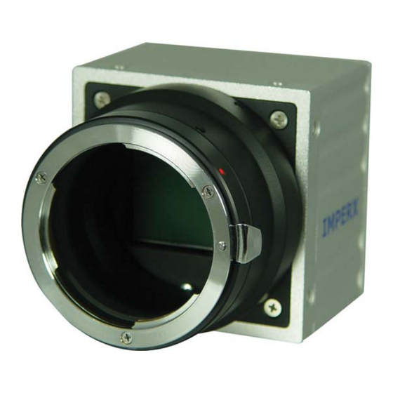
Page 33: Figure 1.8A - C-Mount Gige Cameras - Ipx-Vga-G / 1M48-G / 2M30-G / 2M30H-G
LYNX Hardware User’s Manual Figure 1.8a - C-mount GigE cameras – IPX-VGA-G / 1M48-G / 2M30-G / 2M30H-G Figure 1.8b - F-mount GigE cameras – IPX-4M15-G / 11M5-G / 16M3-G 33 of 216... -
Page 34: Figure 1.9 - Peltier Cooled Cl And Gige Cameras - Ipx-4M15T / 11M5T / 16M3T
LYNX Hardware User’s Manual Figure 1.9 – Peltier cooled CL and GigE cameras – IPX-4M15T / 11M5T / 16M3T Figures 1.10 to 1.15 show the dimensional drawings of IPX-VGA, IPX-1M48, IPX-2M30/H, IPX-4M15, IPX-11M5 and IPX-16M3 respectively. All dimensions are in millimeters. As of 10.01.06 11M5-L and all GigE models are shipped with black finned mid housing for better heat transfer. -
Page 35: Figure 1.10A - Ipx-Vga120-L And Ipx-Vga210-L Dimensional Drawings
LYNX Hardware User’s Manual IPX-VGA120-L / IPX-VGA210-L Figure 1.10a - IPX-VGA120-L and IPX-VGA210-L Dimensional Drawings. 35 of 216... -
Page 36: Figure 1.10B - Ipx-Vga210-G (Silver Body) Dimensional Drawings
LYNX Hardware User’s Manual IPX-VGA210-G Figure 1.10b - IPX-VGA210-G (Silver Body) Dimensional Drawings 36 of 216... - Page 37 LYNX Hardware User’s Manual IPX-VGA210-G Figure 1.10c - IPX-VGA210-G (Black Body) Dimensional Drawings 37 of 216...
-
Page 38: Figure 1.11A - Ipx-1M48-L Dimensional Drawings
LYNX Hardware User’s Manual IPX-1M48-L Figure 1.11a - IPX-1M48-L Dimensional Drawings 38 of 216... -
Page 39: Figure 1.11B - Ipx-1M48-G (Silver Body) Dimensional Drawings
LYNX Hardware User’s Manual IPX-1M48-G Figure 1.11b - IPX-1M48-G (Silver Body) Dimensional Drawings 39 of 216... - Page 40 LYNX Hardware User’s Manual IPX-1M48-G Figure 1.11c - IPX-1M48-G (Black Body) Dimensional Drawings 40 of 216...
-
Page 41: Figure 1.12A - Ipx-2M30-L And Ipx-2M30H-L Dimensional Drawings
LYNX Hardware User’s Manual IPX-2M30-L / IPX-2M30H-L Figure 1.12a - IPX-2M30-L and IPX-2M30H-L Dimensional Drawings 41 of 216... -
Page 42: Figure 1.12B - Ipx-2M30-G And Ipx-2M30H-G (Silver Body) Dimensional Drawings
LYNX Hardware User’s Manual IPX-2M30-G / IPX-2M30H-G Figure 1.12b - IPX-2M30-G and IPX-2M30H-G (Silver Body) Dimensional Drawings 42 of 216... -
Page 43: Figure 1.12C - Ipx-2M30-G And Ipx-2M30H-G (Black Body) Dimensional Drawings
LYNX Hardware User’s Manual IPX-2M30-G / IPX-2M30H-G Figure 1.12c - IPX-2M30-G and IPX-2M30H-G (Black Body) Dimensional Drawings 43 of 216... -
Page 44: Figure 1.13A - Ipx-4M15-L Dimensional Drawings
LYNX Hardware User’s Manual IPX-4M15-L Figure 1.13a - IPX-4M15-L Dimensional Drawings 44 of 216... -
Page 45: Figure 1.13B - Ipx-4M15-G (Silver Body) Dimensional Drawings
LYNX Hardware User’s Manual IPX-4M15-G Figure 1.13b - IPX-4M15-G (Silver Body) Dimensional Drawings 45 of 216... - Page 46 LYNX Hardware User’s Manual IPX-4M15-G Figure 1.13c - IPX-4M15-G (Black Body) Dimensional Drawings 46 of 216...
-
Page 47: Figure 1.14A - Ipx-11M5-L (Silver Body) Dimensional Drawings
LYNX Hardware User’s Manual IPX-11M5-L Figure 1.14a - IPX-11M5-L (Silver Body) Dimensional Drawings 47 of 216... -
Page 48: Figure 1.14B - Ipx-11M5-L (Black Body) Dimensional Drawings
LYNX Hardware User’s Manual IPX-11M5-L Figure 1.14b - IPX-11M5-L (Black Body) Dimensional Drawings 48 of 216... -
Page 49: Figure 1.14C - Ipx-11M5-G (Silver Body) Dimensional Drawings
LYNX Hardware User’s Manual IPX-11M5-G Figure 1.14c - IPX-11M5-G (Silver Body) Dimensional Drawings 49 of 216... -
Page 50: Figure 1.14D - Ipx-11M5-G (Black Body) Dimensional Drawings
LYNX Hardware User’s Manual IPX-11M5-G Figure 1.14d - IPX-11M5-G (Black Body) Dimensional Drawings 50 of 216... -
Page 51: Figure 1.15A - Ipx-16M3-L Dimensional Drawings
LYNX Hardware User’s Manual IPX-16M3-L Figure 1.15a - IPX-16M3-L Dimensional Drawings 51 of 216... -
Page 52: Figure 1.15B - Ipx-16M3-G Dimensional Drawings
LYNX Hardware User’s Manual IPX-16M3-G Figure 1.15b - IPX-16M3-G Dimensional Drawings 52 of 216... -
Page 53: Figure 1.16 - Ipx-4M15T/11M5T/16M3T Dimensional Drawings
LYNX Hardware User’s Manual IPX-4M15T, IPX-11M5T, IPX-16M3T Figure 1.16 – IPX-4M15T/11M5T/16M3T Dimensional Drawings 53 of 216... -
Page 54: Optical
F-mount lenses, which have a 46.5 mm back focal distance – Figure 1.17. An F-mount lens can be used with a C-mount camera via an F-mount to C-mount adapter, which can be purchased separately – refer to the Imperx web side for more information. The camera performance and signal to noise ratio depends on the illumination (amount of light) reaching the sensor and the exposure time. -
Page 55: Environmental
LYNX Hardware User’s Manual 1.5.3 Environmental The camera is designed to operate from -5 to 50 C in a dry environment. The relative humidity should not exceed 80% non-condensing. Always keep the camera as cool as possible. Always allow sufficient time for temperature equalization, if the camera was kept below 0 The camera should be stored in a dry environment with the temperature ranging from -10... -
Page 56: Chapter 2 - Camera Features
LYNX Hardware User’s Manual Chapter 2 – Camera Features Camera Features This chapter discusses the camera’s features and their use. 56 of 216... -
Page 57: Resolution And Frame Rate
LYNX Hardware User’s Manual 2.1 RESOLUTION AND FRAME RATE 2.1.1 Single Output When operating in the single output mode, all pixels are shifted out of the HCCD register towards the left video amplifier – Video L (Figure 2.1). The resulting image has a normal orientation, full resolution and a frame rate as shown in Table 2.1. -
Page 58: Dual Output
LYNX Hardware User’s Manual 2.1.2 Dual Output When operating in a dual output mode, the image is split in two equal parts, each side consisting of half of the horizontal pixels and the full vertical lines. The first (left) half of the pixels are shifted out of the HCCD register towards the left video amplifier –... -
Page 59: Center Columns Output (Ipx-Vga210-L/G Only)
LYNX Hardware User’s Manual 2.1.3 Center Columns Output (IPX-VGA210-L/G only) The ‘center columns’ output mode is only available in the IPX-VGA210-L/G. In this mode the image field has only 228 horizontal pixels located in the center of the imager – Figure 2.3. When operating in a single output mode, all 228 pixels are shifted out of the HCCD register towards the left video amplifier –... -
Page 60: Figure 2.4 - Center Columns Output In Dual Mode Of Operation
LYNX Hardware User’s Manual Figure 2.4 - Center Columns Output in Dual Mode of Operation Figure 2.5 - Center Columns Output in Dual Tap Mode 60 of 216... -
Page 61: Timing Diagrams
LYNX Hardware User’s Manual 2.1.4 Timing Diagrams IPX-VGA120-L, IPX-VGA210-L/G In the single mode each line consists of 12 empty pixels (E1 – E12), followed by 24 masked pixels used for black reference (R1 – R24), followed by 4 buffer pixels (B1 – B4), followed by 640 active data pixels (D1 –... -
Page 62: Figure 2.7 - Dual Output Line Timing (Ipx-Vga210-L/G)
LYNX Hardware User’s Manual 4 buffer 320 active 12 empty 24 dark pixels data pixels pixels pixels 300 ns 600 ns 100 ns 8000 ns DATA 1 D639 - 0 - - 0 - DATA 2 D640 - 0 - - 0 - LVAL Figure 2.7 - Dual Output Line Timing (IPX-VGA210-L/G) -
Page 63: Ipx-Vga210-L/G - Center Columns Operation
LYNX Hardware User’s Manual IPX-VGA210-L/G – Center Columns Operation In the center columns single mode, each line consists of 228 active data pixels (D1 – D228), followed by 18 dark (over-clocked) pixels (R1 – R18) – Figure 2.9. In the center columns dual mode, each line consists of 6 masked (over-clocked) pixels (R1 –... -
Page 64: Ipx-1M48-L/G
LYNX Hardware User’s Manual IPX-1M48-L/G In the single mode, each line consists of 8 empty pixels (E1 – E8), followed by 12 masked pixels used for black (dark) reference (R1 – R12), followed by 2 buffer pixels (B1, B2), followed by 1000 active pixels (D1 –... -
Page 65: Figure 2.13 - Single / Dual Output Frame Timing (Ipx-1M48-L/G)
LYNX Hardware User’s Manual 4 dark lines 2 buffer lines 2 buffer lines 1000 active lines TL HB DATA - 0 - - 0 - - 0 - - 0 - - 0 - - 0 - DL1000 - 0 - - 0 - - 0 - - 0 -... -
Page 66: Ipx-2M30-L/G
LYNX Hardware User’s Manual IPX-2M30-L/G In the single mode, each line consists of 4 empty pixels (E1 – E4), followed by 16 masked pixels used for black (dark) reference (R1 – R16), followed by 4 buffer pixels (B1 – B4), followed by 1600 active data pixels (D1 –... -
Page 67: Figure 2.16 - Single / Dual Output Frame Timing (Ipx-2M30-L/G)
LYNX Hardware User’s Manual 2 dark lines 4 buffer lines 4 dark lines 4 buffer lines 1200 active lines TL HB DATA - 0 - - 0 - - 0 - - 0 - - 0 - - 0 - DL1200 - 0 - - 0 -... -
Page 68: Ipx-2M30H-L/G
LYNX Hardware User’s Manual IPX-2M30H-L/G In the single mode, each line consists of 4 empty pixels (E1 – E4), followed by 28 masked pixels used for black (dark) reference (R1 – R28), followed by 4 buffer pixels (B1 – B4), followed by 1920 active data pixels (D1 –... -
Page 69: Figure 2.19 - Single / Dual Output Frame Timing (Ipx-2M30H-L/G)
LYNX Hardware User’s Manual 2 buffer lines 4 dark lines 4 dark lines 2 buffer lines 1080 active lines TL HB DATA - 0 - - 0 - - 0 - - 0 - - 0 - - 0 - DL1080 - 0 - - 0 -... -
Page 70: Ipx-4M15-L/G
LYNX Hardware User’s Manual IPX-4M15-L/G In single mode, each line consists of 12 empty pixels (E1 – E12), followed by 28 masked pixels used for black (dark) reference (R1 – R28), followed by 4 buffer pixels (B1 – B4), followed by 2048 active data pixels (D1 –... -
Page 71: Figure 2.22 - Single / Dual Output Frame Timing (Ipx-4M15-L/G)
LYNX Hardware User’s Manual 10 dark lines 8 buffer lines 6 buffer lines 2048 active lines TL HB DATA - 0 - - 0 - RL10 - 0 - - 0 - - 0 - - 0 - DL2048 - 0 - - 0 - - 0 - - 0 -... -
Page 72: Ipx-11M5-L/G
LYNX Hardware User’s Manual IPX-11M5-L/G In the single mode, each line consists of 4 empty pixels (E1 – E4), followed by 20 masked pixels used for black reference (R1 – R20), followed by 16 buffer pixels (B1 – B16), followed by 4000 active data pixels (D1 –... -
Page 73: Figure 2.25 - Single / Dual Output Frame Timing (Ipx-11M5-L/G)
LYNX Hardware User’s Manual 8 buffer lines 16 dark lines 2672 active lines 16 dark lines 8 buffer lines TL HB DATA - 0 - - 0 - RL16 - 0 - - 0 - BL8 - 0 - - 0 - DL2672 - 0 - - 0 -... -
Page 74: Ipx-16M3-L/G
LYNX Hardware User’s Manual IPX-16M3-L/G In the single mode, each line consists of 16 empty pixels (E1 – E16), followed by 28 masked pixels used for black reference (R1 – R28), followed by 16 buffer pixels (B1 – B16), followed by 4872 active data pixels (D1 –... -
Page 75: Figure 2.27 - Dual Output Line Timing (Ipx-16M3-L/G)
LYNX Hardware User’s Manual 16 buffer 2436 active 13 empty 28 dark pixels data pixels pixels pixels 464 ns 1000 ns 572 ns 87000 ns DATA 1 - 0 - R28 B1 - 0 - D4871 DATA 2 D4872 - 0 - - 0 - LVAL Figure 2.27 - Dual Output Line Timing (IPX-16M3-L/G) -
Page 76: Area Of Interest
LYNX Hardware User’s Manual 2.2 AREA OF INTEREST 2.2.1 Horizontal and Vertical Window Horizontal and vertical windowing (Area Of Interest) is supported in all LYNX cameras. Emphasizing a particular area of interest in horizontal direction is possible by using a horizontal window feature, where the beginning part of each line (pixel 1 to ‘Start Pixel’) and the end of each line (‘End Pixel’... -
Page 77: Calculating The Frame Rate Using Vertical Window
LYNX Hardware User’s Manual IPX- IPX- IPX- IPX- IPX- IPX- IPX- Feature VGA210-L 1M48-L 2M30-L 2M30H-L 4M15-L 11M5-L 16M3-L Start Pixel - Min. Start Pixel - Max. 1599 1919 2047 3999 4871 End Pixel - Min. End Pixel - Max. 1000 1600 1920... -
Page 78: Ipx-Vga120-L
LYNX Hardware User’s Manual IPX-VGA120-L FR [fps] = 1 / [(0.70 x 10 x (492 – WS)) + T + (WS x T (2.1a) is a constant = 35.35 x 10 sec., and T is the active line duration (T 18.38 x 10 sec). -
Page 79: Ipx-Vga210-L/G
LYNX Hardware User’s Manual IPX-VGA210-L/G FR [fps] = 1 / [(0.70 x 10 x (492 – WS)) + T + (WS x T (2.1b) is a constant (T = 35.35 x 10 for single and dual mode), and T is the active line duration (T = 18.38 x 10 for single mode, T... -
Page 80: Ipx-1M48-L/G
LYNX Hardware User’s Manual IPX-1M48-L/G FR [fps] = 1 / [(7.2 x 10 x (1010 – WS)) + T + (WS x T (2.1c) is a constant (T = 60.90 x 10 for single and dual mode), and T is the active line duration (T = 33.1 x 10 for single mode, and T... -
Page 81: Ipx-2M30-L/G
LYNX Hardware User’s Manual IPX-2M30-L/G FR [fps] = 1 / [(4.00 x 10 x (1214 – WS)) + T + (WS x T (2.1d) is a constant (T = 82 x 10 for single mode, and T = 62 x 10 dual mode), and T is the active line duration (T = 45.18 x 10... -
Page 82: Ipx-4M15-L/G
LYNX Hardware User’s Manual IPX-4M15-L/G FR [fps] = 1 / [(4.00 x 10 x (2072 – WS)) + T + (WS x T (2.1e) is a constant (T = 122.1 x 10 for single mode, and T = 95.7 x 10 for dual mode), and T is the active line duration (T = 57.38 x 10... -
Page 83: Ipx-11M5-L/G
Note: The minimum vertical window size for the IPX-11M5 is 400 lines. you require support for less than 400 lines then please contact Imperx. Figure 2.35 - Frame Rate vs. Vertical Window Size (IPX-11M5-L/G) 83 of 216... -
Page 84: Ipx-16M3-L/G
Note: The minimum vertical window size for the IPX-16M3 is 400 lines. If you require support for less than 400 lines then please contact Imperx. Figure 2.36 - Frame Rate vs. Vertical Window Size (IPX-16M3-L/G) 84 of 216... -
Page 85: Binning
LYNX Hardware User’s Manual 2.3 BINNING Binning uses the CCD sensor to combine adjacent pixels in both directions to effectively create larger pixels and less resolution. In 2:1 horizontal binning mode, two adjacent pixels in each line are summed together (in the horizontal direction), for example, pixels 1+2, 3+4, 5+6, …... - Page 86 LYNX Hardware User’s Manual CAUTION NOTE Horizontal or vertical binning used alone changes the aspect ratio of the image in the vertical or horizontal direction. To correct this, use horizontal and vertical binning simultaneously. The frame-grabber vertical and horizontal resolution should be changed to reflect the actual number of active pixels and lines.
-
Page 87: Exposure Control
LYNX Hardware User’s Manual 2.4 EXPOSURE CONTROL 2.4.1 Electronic Shutter During normal camera operation, the exposure time is fixed and determined by the frame rate. The electronic shutter can be used to precisely control the image exposure time under bright light conditions. The electronic shutter does not affect the frame rate, it only reduces the amount of electrons collected. -
Page 88: Long Integration
LYNX Hardware User’s Manual the camera frame rate from 2 fps (0.5 s integration time) up to the nominal camera speed – refer to Table 2.1, with a precision of 1.0 fps. Optionally, the user can enter the desired frame rate in units of time instead of units of fps. When the user the desired frame rate, the camera will calculate the corresponding integration time. -
Page 89: Figure 2.40 - Long Integration
LYNX Hardware User’s Manual be calculated using formula 4.2. This mode is displayed on the LED by slow pulsation with a 2 second interval – refer to Status LED section. Frame rate [fps] = 1 / long integration time [sec] (4.2) Long Integration Time Standard Frame Time... -
Page 90: External Trigger
LYNX Hardware User’s Manual 2.5 EXTERNAL TRIGGER 2.5.1 Triggering Inputs In the normal mode of operation, the camera is free running. Using the external trigger mode allows the camera to be synchronized to an external timing pulse. There are two general modes available for external triggering – software and hardware. -
Page 91: Figure 2.41B - Hardware Trigger Electrical Connection - Gige Output
LYNX Hardware User’s Manual LYNX Cameras with GigE Output In hardware triggering mode the camera receives the trigger signal coming from the connector located on the back of the camera. The hardware trigger input in LYNX with GigE output is directly connected to the camera hardware –... -
Page 92: Standard Triggering - Programmable Exposure
LYNX Hardware User’s Manual 2.5.2 Standard Triggering - Programmable Exposure When the standard triggering mode is enabled, the camera idles and waits for a trigger signal. Upon receiving the external trigger signal, the camera clears the horizontal and vertical registers, sends one 5 microseconds shutter pulse to clear the pixels and starts integration. -
Page 93: Fast Synchronized Triggering - Rapid Capture
LYNX Hardware User’s Manual TRIGGER SHUTTER EXPOSURE First Frame Exposure VCCD FVAL DATA DATA Out STROBE Only if the strobe is enabled Figure 2.42 - Standard Triggering Timing 2.5.3 Fast Synchronized Triggering – Rapid Capture Fast synchronized triggering (a.k.a. rapid capture) provides the ability to run the camera in a slave mode, allowing several cameras to be synchronized with an external master trigger signal. -
Page 94: Double Exposure Triggering
LYNX Hardware User’s Manual TRIGGER EXPOSURE Exposure N+2 Exposure N-1 Exposure N Exposure N+1 Exposure N+3 DATA DATA N-2 DATA N-1 DATA N DATA N+1 DATA N+2 STROBE Only if the strobe is enabled Figure 2.43 - Fast Synchronized Triggering - Rapid Capture 2.5.4 Double Exposure Triggering Double exposure allows two events (two images) to be captured in rapid... -
Page 95: Figure 2.44 - Double Exposure Triggering
LYNX Hardware User’s Manual CAUTION NOTE It is recommended that the minimum time duration between the events is greater then the vertical transfer pulse duration: a. 5 microseconds for VGA, 1M48, 2M30, 2M30H and 4M15. b. 10 microseconds for 11M5 and 16M3. TRIGGER SHUTTER EXPOSURE... -
Page 96: Strobe Output
LYNX Hardware User’s Manual 2.6 STROBE OUTPUT 2.6.1 Strobe Positioning The strobe output is used to synchronize an external light source with the camera timing, and thus to maximize the camera efficiency in low light level conditions. The optimal strobe signal position is achieved by the positioning of a short pulse, STROBE, (duration 200 μs) with respect to the vertical transfer pulse VCCD - Figure 2.45. -
Page 97: Figure 2.46A - Strobe Output Electrical Connection (Internal) - Camera Link
LYNX Hardware User’s Manual CAUTION NOTE The maximum voltage difference between the strobe outputs is 8 volts! The maximum output current must not exceed 40mA! + STROBE OUT + 5.0V 2N3904 1.0K - STROBE OUT FROM CAMERA C A M E R A Figure 2.46a - Strobe Output Electrical Connection (Internal) –... -
Page 98: Strobe Electrical Connectivity - Lynx With Gige Output
LYNX Hardware User’s Manual 2.6.3 Strobe Electrical Connectivity – LYNX with GigE Output The strobe output is directly connected to the camera hardware and is 3.3 V LVTTL compatible signal. The maximum output current MUST NOT exceed 8 mA. Figure 2.47 - Strobe Output Electrical Connection (Internal) - GigE Termination: 200 Ω... -
Page 99: Gain And Offset
LYNX Hardware User’s Manual 2.7 GAIN and OFFSET The camera has dual analog signal processors (or Analog Front End – AFE), one per channel. It features two independent 12 bit 40 MHz processors, each containing a differential input sample-and-hold amplifier (SHA), digitally controlled variable gain amplifier (VGA), black level clamp and a 12-bit ADC. -
Page 100: Data Output Format
LYNX Hardware User’s Manual 2.8 DATA OUTPUT FORMAT The internal camera processing of the CCD data is performed in 12 bits. The camera can output the data in 12, 10 or 8 bit format. During this standard bit reduction process, the least significant bits are truncated – Figure 2.49. If the 12 bit original camera data is D0 (LSB) to D11 (MSB), and 12 bit output: camera is set to output 12 bit data, the 12 output bits are mapped... -
Page 101: Transfer Function Correction - User Lut
LYNX Hardware User’s Manual 2.9 TRANSFER FUNCTION CORRECTION – USER LUT The user defined LUT (Lookup Table) feature allows the user to modify and transform the original video data into any arbitrary value – Figure 2.50. Any 12-bit value can be transformed into any other 12-bit value. The camera supports two separate lookup tables, each consisting of 2048 entries, with each entry being 12 bits wide. -
Page 102: User Defined Lut - Examples
LYNX Hardware User’s Manual Figure 2.51 - Gamma Corrected Video Signal 2.9.2 User Defined LUT - Examples The user can define any 12-bit to 12-bit transformation as a user LUT and can upload it to the camera using the configuration utility software. If the camera resolution is set to 8 or 10 bit, the camera will truncate the corresponding LSB’s (see section 2.8). -
Page 103: Figure 2.52 - Custom Lut
LYNX Hardware User’s Manual Modified TF Original TF Input signal Figure 2.52 - Custom LUT Example 2 – Knee correction In this example only 2 knee points have been introduced, the first one is at (400H) and the second at (A00H). The number of knee points is not limited. Modified TF Original TF Input signal... -
Page 104: Figure 2.54 - Contrast Correction
LYNX Hardware User’s Manual Example 3 – Contrast Correction Modified TF Original TF Input signal Figure 2.54 - Contrast Correction Example 4 – Negative Image Modified TF Original TF Input signal Figure 2.55 - Negative Image 104 of 216... - Page 105 LYNX Hardware User’s Manual Example 5 – Digital Shift The “Digital Shift” feature allows the user to change the group of bits sent to the camera output and therefore manipulate the camera brightness and contrast. The internal camera processing of the data is 12 bits. If the camera is set to output 10 bits of data then the two least significant bits are truncated.
- Page 106 LYNX Hardware User’s Manual Example C. Performing a non-standard 12 to 10 bit conversion: The original camera data is D0 (LSB) to D11 (MSB) Input Data - 12 bit Create a LUT, which truncates the 2 most significant bits (bits are shifted with two to the right).
-
Page 107: Dynamic Signal-To-Noise Correction
LYNX Hardware User’s Manual 2.10 DYNAMIC SIGNAL-TO-NOISE CORRECTION As was described in the section 2.7 (Gain and Offset), the reference black level on each CCD output fluctuates around 0V – Figure 2.56. The AFE offset correction works on the entire image and if there are noise fluctuations on a line level, the AFE is not capable of correcting them. -
Page 108: Image Reversal
LYNX Hardware User’s Manual 2.11 IMAGE REVERSAL When operating in the image reversal mode, all pixels are shifted to the output in the reverse order. The resultant image appears left/right mirrored in the horizontal direction – Figure 2.57. This feature could be useful if the camera receives a mirrored image (i.e. -
Page 109: Negative Image
LYNX Hardware User’s Manual 2.12 NEGATIVE IMAGE When operating in the negative image mode, the value of each pixel is inverted. The resultant image appears negative – Figure 2.58. This feature could be useful if the camera receives a negative image (i.e. image from microfilms, prints or slides). In this mode the image has a normal vertical and horizontal orientation and full resolution. -
Page 110: Camera Interface
LYNX Hardware User’s Manual 2.13 CAMERA INTERFACE 2.13.1 Status LED The camera has a green LED, located on the back panel, which indicates the camera status and mode of operation. • LED is steady ON – Normal operation. The user is expected to see a normal image coming out of the camera. -
Page 111: Integration Time Monitor
LYNX Hardware User’s Manual the LED on the back of the camera starts to blink rapidly. The alarm is for indication only and does not prevent the camera from continue to operate normally. 2.13.3 Integration Time Monitor The camera has a built in integration time monitor. In any mode of operation ( i.e. -
Page 112: Test Mode
LYNX Hardware User’s Manual 2.14 TEST MODE The camera can output three test images (two fixed and one moving), which can be used to verify the camera’s general performance and connectivity to the frame grabber. This ensures that all the major modules in the hardware are working properly and that the connection between the frame grabber and the camera is synchronized (i.e., the camera parameters: # pixels, # lines, # bits, output mode, communication rate, etc. -
Page 113: Automatic Iris Control
LYNX Hardware User’s Manual 2.15 AUTOMATIC IRIS CONTROL The camera has an optional auto iris control feature. If enabled, the camera calculates the average image brightness within the frame and compares it to a user specified threshold level – refer to the ‘sai’ command. If the calculated brightness level is less then the threshold, the camera sends a signal to open the lens iris. -
Page 114: Flat Field Correction
‘sfc on’ ( Set Flatfield Correction – On ) command. Each Imperx camera is shipped with the Flat Field Correction file that was created for that camera during factory final testing. Users may wish, however, to create their own Flat Field Correction file because of the uniqueness of their operating environment ( i.e. -
Page 115: Figure 2.61 - Original Image Showing 'Shading' Effect
LYNX Hardware User’s Manual Figure 2.61 – Original image showing ‘shading’ effect Figure 2.62 – Flat Field Corrected image 115 of 216... -
Page 116: Thermo-Electric Cooling ( Tec )
Imperx “TEC Nitrogen-check/purge/refill” application note for details. The camera should not be exposed to extreme pressure and temperature changes to prevent the loss of Nitrogen from the CCD chamber. Consult Imperx for details TEC cooled cameras require between 1A and 3A of current at 12Vdc depending on camera model and operating mode/condition which has to be considered when camera is not powered from the supplied AC/DC adapter. -
Page 117: Chapter 3 - Camera Configuration
LYNX Hardware User’s Manual Chapter 3 – Camera Configuration Camera Configuration This chapter discusses how to configure the camera’s operating parameters. 117 of 216... -
Page 118: Overview
LYNX Hardware User’s Manual 3.1 Overview The Lynx series of cameras are highly programmable and flexible. All of the camera’s features and operating parameters can be controlled by the user. The user communicates with the camera using simple ASCII commands via the Camera Link’s serial interface. -
Page 119: Configuration Memory
LYNX Hardware User’s Manual 3.2 Configuration Memory The camera has a built-in configuration memory divided into 4 segments: ‘work- space’, ‘factory-space’, ‘user-space #1’ and ‘user-space #2’. The ‘work-space’ segment contains the current camera settings while the camera is powered-up and operational. -
Page 120: Command Format
LYNX Hardware User’s Manual 3.3 Command Format Command strings consist of a command token followed by up to two parameters. The format of the command string is: <command> <parm1> <parm2><cr> In response to the receipt of a command string, the camera will perform the intended operation and return a response string. -
Page 121: Command Help
LYNX Hardware User’s Manual 3.4 Command Help The camera will return a list of available commands when the user enters the ‘h’ command. For command specific help, enter , and the camera will display the ‘h <cmd>’ command definition and syntax. For example, entering yields: ‘h svw’... -
Page 122: Startup Procedure
LYNX Hardware User’s Manual 3.5 Startup procedure Upon power on or receipt of an command, the camera performs the following ‘rc’ steps: The RISC processor runs and executes code from internal read only memory. The boot loader code sends the string: “Boot loader version x.y running…”... -
Page 123: Saving And Restoring Settings
LYNX Hardware User’s Manual 3.6 Saving and Restoring Settings Operational settings for the camera may be stored for later retrieval in its non- volatile memory. Three separate configuration spaces exist for storing these settings: ‘factory’ space, ‘user #1’ space and ‘user #2’ space. The factory space is pre-programmed by factory personnel during the manufacturing process. -
Page 124: Load From User ( )
LYNX Hardware User’s Manual 3.6.4 Load From User ( ‘lfu’ command instructs the camera to load its workspace from one of ‘lfu’ the two user spaces. All current workspace settings will be replaced with the contents of the selected user space. Syntax: lfu <1|2>... -
Page 125: Retrieving Manufacturing Data
LYNX Hardware User’s Manual 3.7 Retrieving Manufacturing Data The camera contains non-volatile memory that stores manufacturing related information. This information is programmed in the factory during the manufacturing process. 3.7.1 Get Manufacturing Data ( ‘gmd’ command returns a listing of all manufacturing data. ‘gmd’... -
Page 126: Get Software Version
LYNX Hardware User’s Manual 3.7.5 Get Software Version ( ‘gsv’ command returns the camera’s software version. ‘gsv’ Syntax: Response: Camera responds with its software version, bootloader version and customer ID ( for custom software ). Example: SW v1.0 BL v2.0 CUST 4 126 of 216... -
Page 127: Command Description
LYNX Hardware User’s Manual 3.8 Command Description 3.8.1 Horizontal Window 3.8.1.1 Set Horizontal Window ( ‘shw’ command sets the horizontal area of interest. The camera will ‘shw’ deliver to the Camera Link interface, per line, only the range of pixels specified by this command. -
Page 128: Vertical Window
LYNX Hardware User’s Manual 3.8.2 Vertical Window 3.8.2.1 Set Vertical Window ( ‘svw’ command sets the vertical area of interest. The camera will ‘svw’ deliver to the Camera Link interface, per frame, only the range of lines specified by this command. Using this command increases the effective frame rate of the camera and also reduces the automatic exposure time ( when shutter is disabled ). -
Page 129: Shutter Time
LYNX Hardware User’s Manual 3.8.3 Shutter Time 3.8.3.1 Set Shutter Time ( ‘sst’ command sets the shutter timing. ‘sst’ Syntax: sst <off|i> Parameter: Disables the shutter mode. The shutter time in units of uSeconds. Range: min=50 max=the lesser of 500,000 or 1/frame rate Example: Sets the shutter time to 80 uSeconds. -
Page 130: Long Integration
LYNX Hardware User’s Manual 3.8.4 Long Integration 3.8.4.1 Set Long Integration ( ‘sli’ command sets the long integration timing. ‘sli’ Syntax: sli <off|i> Parameter: Disables the long integration mode. The long integration time in units of mSeconds. Range: min=10 max=10,000 Example: Sets the long integration time to 750 sli 750... -
Page 131: Strobe Position
LYNX Hardware User’s Manual 3.8.5 Strobe Position 3.8.5.1 Set Strobe Position ( ‘ssp’ command sets the position of the strobe pulse output. The ‘ssp’ strobe pulse position is set relative to the end of the frame. Syntax: ssp <off|i> Parameter: Disables the strobe. -
Page 132: Analog Gain
LYNX Hardware User’s Manual 3.8.6 Analog Gain 3.8.6.1 Set Analog Gain ( ‘sag’ command sets the analog gain of the camera. ‘sag’ Syntax: sag <0|1|2> <i> <j> Parameter #1: Sets both taps to the same gain or to different gains. Selects tap #1. -
Page 133: Analog Offset
LYNX Hardware User’s Manual 3.8.7 Analog Offset 3.8.7.1 Set Analog Offset ( ‘sao’ command sets the analog offset of the camera. ‘sao’ Syntax: sao <0|1|2> <i> <j> Parameter #1: Sets both taps to the same offset or to different offsets. Selects tap #1. -
Page 134: Dual Tap Mode
LYNX Hardware User’s Manual 3.8.8 Dual Tap mode 3.8.8.1 Set Dual Mode ( ‘sdm’ command sets the camera to operate in either single or dual ‘sdm’ tap mode. Syntax: sdm <on|off> Parameter: Selects dual tap operation. Selects single tap opertion. Example: Enables dual tap operation. -
Page 135: Bit Depth
LYNX Hardware User’s Manual 3.8.9 Bit Depth 3.8.9.1 Set Bit Depth ( ‘sbd’ command sets the bit depth of the camera. ‘sbd’ Syntax: sbd <8|10|12> Parameter: Selects 8 bit operation. Selects 10 bit operation. Selects 12 bit operation. Example: Enables 10 bit operation. sbd 10 3.8.9.2 Get Bit Depth (... -
Page 136: Lookup Table Operation
‘glh’ lookup table. Syntax: glh <1|2> Response: Lookup table header text Example: User enters command. glh 1 Camera responds Function is Gamma 0.45 with LUT header Created by Imperx, Inc. text. Date 3/19/05 136 of 216... -
Page 137: Noise Correction Processing
LYNX Hardware User’s Manual 3.8.11 Noise Correction processing 3.8.11.1 Set Noise Correction ( ‘snc’ command instructs the camera to perform noise correction ‘snc’ processing on all incoming pixels. During this process, the camera averages the leading dark pixels in each line and determines what the average noise level is. -
Page 138: Horizontal Mode
LYNX Hardware User’s Manual 3.8.12 Horizontal mode 3.8.12.1 Set Horizontal Mode ( ‘shm’ command configures the camera to operate in the normal, ‘shm’ window, binning or center modes. The normal mode turns off window, binning and center modes. In the windowing mode of operation, the horizontal area of interest is defined by the command. -
Page 139: Vertical Mode
LYNX Hardware User’s Manual 3.8.13 Vertical Mode 3.8.13.1 Set Vertical Mode ( ‘svm’ command configures the camera to operate in either the ‘svm’ normal, windowing or binning modes. The normal mode turns off both windowing and binning. In the windowing mode of operation, the vertical area of interest is defined by the command. -
Page 140: Test Pattern Generation
LYNX Hardware User’s Manual 3.8.14 Test Pattern generation 3.8.14.1 Set Test Mode ( ‘gtm’ command instructs the camera to enter a test mode and ‘stm’ deliver a test pattern to the Camera Link interface. This command is useful during frame grabber configuration and when troubleshooting the camera to frame grabber interface. -
Page 141: Image Reversal Mode
LYNX Hardware User’s Manual 3.8.15 Image Reversal mode 3.8.15.1 Set Image Reversal ( ‘sir’ command instructs the camera to perform image reversal. ‘sir’ During image reversal the camera will deliver pixels, to the Camera Link interface, in the reverse order from which they were received by the CCD sensor resulting in a mirror image being displayed. -
Page 142: Trigger Operation
LYNX Hardware User’s Manual 3.8.16 Trigger operation 3.8.16.1 Set Trigger ( ‘str’ command instructs the camera to exit the free running mode ‘str’ of operation and to enter into a trigger mode. In the trigger mode, the camera will idle and wait for a trigger event to occur. When the trigger event occurs, the camera will begin processing images and deliver them to the Camera Link interface. -
Page 143: Set Trigger Duration
LYNX Hardware User’s Manual 3.8.16.3 Set Trigger Duration ( ‘std’ command sets the number of frames to be transmitted after a ‘std’ trigger event occurs. Syntax: std <i> Parameter: The number of frames to be transmitted after the trigger. A value between 250 and 255 indicates that the camera should free run after the trigger. -
Page 144: Set Pre-Exposure
LYNX Hardware User’s Manual 3.8.16.7 Set Pre-Exposure ( ‘spe’ command sets the exposure time for the first frame after a ‘spe’ trigger event when the trigger is in the ‘standard’ mode.. The first frame after a trigger will be exposed for the length of time specified. All subsequent frames will be exposed per the shutter setting ( set by the command ). - Page 145 LYNX Hardware User’s Manual 3.8.16.9 Set Double Exposure ( ‘sde’ command sets the exposure time for the first frame after a ‘sde’ trigger event when the trigger is in the ‘double’ mode. The first frame after a trigger will be exposed for the length of time specified. All subsequent frames will be exposed per the shutter setting ( set by the command ).
-
Page 146: Negative Image Mode
LYNX Hardware User’s Manual 3.8.17 Negative Image mode 3.8.17.1 Set Negative Image ( ‘sni’ command instructs the camera to perform image inversion. ‘sni’ During image inversion, the camera will perform a one’s compliment on all pixels before delivering them to the Camera Link interface resulting in a negative image being displayed. -
Page 147: Temperature Monitoring
LYNX Hardware User’s Manual 3.8.18 Temperature Monitoring 3.8.18.1 Get Current Temperature ( ‘gct’ command returns the current temperature of the camera. The ‘gct’ temperature is in increments of .25 degrees C. Syntax: Response: Camera temperature in degrees centigrade Example: User enters command. Camera responds with current 42.00 temperature. -
Page 148: Set Temperature Threshold
LYNX Hardware User’s Manual 3.8.18.4 Set Temperature Threshold ( ‘stt’ command defines the ‘on’ and ‘off’ temperature thresholds ‘stt’ that will trigger the camera to send temperature warnings. The thresholds are in increments of 1 degrees C. If the camera’s ambient temperature exceeds the ‘on’... -
Page 149: Programmable Frame Rate
LYNX Hardware User’s Manual 3.8.19 Programmable Frame Rate 3.8.19.1 Set Frame Rate ( ‘sfr’ command instructs the camera to throttle the camera frame ‘sfr’ rate from the current free-running rate to a slower rate. This command is useful when the user wishes to reduce the amount of bandwidth required on the Camera Link interface. -
Page 150: Sft' )
LYNX Hardware User’s Manual 3.8.19.3 Set Frame Time ( ‘sft’ command instructs the camera to throttle the camera frame ‘sft’ rate from the current free-running rate to a slower rate. This command is useful when the user wishes to reduce the amount of bandwidth required on the Camera Link interface. -
Page 151: Set Frame Time
LYNX Hardware User’s Manual 3.8.20 Current Speed and Exposure 3.8.20.1 Get Camera Speed ( ‘gcs’ command returns the measured operating speed ( frame rate ) ‘gcs’ of the camera. The current operating speed is determined by a number of settings ( see note below ). The camera is capable of measuring the current frame rate in all modes of operation. - Page 152 LYNX Hardware User’s Manual 3.8.20.2 Get Camera Exposure ( ‘gce’ command returns the measured exposure ( integration ) time of ‘gce’ the camera. The current exposure time is determined by a number of settings ( see note below ). The camera is capable of measuring the current exposure time in all modes of operation.
-
Page 153: Defective Pixel Correction
LYNX Hardware User’s Manual 3.8.21 Defective Pixel Correction 3.8.21.1 Set Defect Correction ( ‘sdc’ command instructs the camera to perform defective pixel ‘sdc’ correction processing on the entire frame. During this process, as the camera process each pixel it looks up the pixel’s location in the on-board Defective Pixel Map ( stored in non-volatile memory ). -
Page 154: Flat Field Correction
LYNX Hardware User’s Manual 3.8.22 Flat Field Correction 3.8.22.1 Set Flatfield Correction ( ‘sfc’ command instructs the camera to perform the Flat Field ‘sfc’ correction procedure. During this procedure, the camera reads a set of Flat Field coefficients from on-board non-volatile memory. It uses these coefficients to compensate for any variations in the pixel responsivity. -
Page 155: Chapter 4 - Lynx Configurator For Cameralink
LYNX Hardware User’s Manual Chapter 4 – LYNX Configurator for CameraLink LYNX Configurator for CameraLink This chapter provides a quick reference to using the Lynx Configurator camera configuration utility for the Camera Link series of Lynx cameras. 155 of 216... -
Page 156: Overview
The configuration utility includes an interactive help file, which will guide you through the camera setup. Lynx CameraLink Frame Grabber Software Software provided by Frame Grabber vendor to display/capture images LynxConfigurator LynxTerminal ImperX ImperX camera configuration camera download utility utility Figure 4.1 - LYNX CameraLink Interface 156 of 216... -
Page 157: Setup
COM port installed on the PC. It will then communicate with each port (.DLL and COM) and attempt to query the attached camera (if any). If it finds an attached Imperx camera, it will read the ‘camera type’ information from the camera. It will then display a list box, which includes all DLLs, ports and cameras that it discovered. - Page 158 LYNX Hardware User’s Manual After having selected the desired camera, the main LYNX Configurator dialog will appear. The graphical user interface is very intuitive and self-explanatory. The configuration utility includes an interactive help file, which will guide you through the GUI controls and camera settings. The user can also reveal a small ‘Terminal Dialog’...
-
Page 159: Graphical User Interface
LYNX Hardware User’s Manual Graphical User Interface The LYNX Configurator is a graphical user interface (GUI) containing six main panels (tabs): • AOI (Area Of Interest) • Trigger • Video Amp • Exposure • Strobe • Auto Iris This section gives a brief description of the different panels and highlights the main camera configuration options. - Page 160 LYNX Hardware User’s Manual When enabled, the center (fast) mode is activated. This Center: feature is only available on the IPX-VGA210L/G. VERTICAL AOI When enabled, the imager has full vertical resolution. Normal: When enabled, the user can set the vertical resolution using Window: the sliders or by entering the desired start and end values.
-
Page 161: Trigger Tab
LYNX Hardware User’s Manual 4.3.2 Trigger Tab The Trigger tab, shown in Figure 4.4, is used to set the different triggering modes. Figure 4.4 - Triggering Tab TRIGGER – selects the trigger source. When enabled, the camera is free running. Off: When enabled, the camera is set to triggering mode, and is External:... -
Page 162: Video Amp Tab
LYNX Hardware User’s Manual CC EXPOSURE CONTROL - CC Exposure control is active only if the camera is set to “CC trigger”. When enabled, the user can also set the exposure time for the Camera: first frame via the “First Frame Exp. – Standard” slider. When enabled, the exposure for the first frame is determined Computer: by the duration (active high) of the trigger pulse. -
Page 163: Auto Iris Tab
LYNX Hardware User’s Manual 4.3.4 Auto Iris Tab Auto Iris Tab controls the auto iris feature – Figure 4.6 Figure 4.6 - Auto Iris Tab Iris Threshold: When enabled, the user can set the iris threshold (brightness of the image) via the slider or by entering the desired value. 4.3.5 Exposure Tab Exposure Tab controls the camera exposure –... -
Page 164: Strobe Tab
LYNX Hardware User’s Manual When enabled, the user can set the camera to Long Long Integration mode. The integration time can be programmed Integration: via the slider or by entering the desired value. This feature is used to extend the camera integration. Programmable When enabled, the user can set the camera frame rate in units of frames/sec via the Frame Rate slider or by entering Frame Rate:... -
Page 165: Common Controls
LYNX Hardware User’s Manual 4.3.7 Common Controls All panels in the LYNX Configurator share the same general control options and menus for “File”, “Boot”, “Test Mode” and “Help” – Figure 4.9. Figure 4.9 – LYNX Configurator main dialog. 165 of 216... - Page 166 LYNX Hardware User’s Manual FILE MENU Loads the camera registers from a saved configuration Load from File: file. Loads the LYNX Configurator GUI with the current Load from status of the camera registers. Workspace: Loads the camera registers and LYNX Configurator Load from GUI with the original (factory) settings.
-
Page 167: Figure 4.10 - Lynx Terminal Dialog Window
LYNX Hardware User’s Manual TEST MODE MENU – This menu select the test pattern generator. Selects the fixed test pattern 1. Fixed pattern 1: Selects the fixed test pattern 2. Fixed pattern 2: Selects the moving test pattern. Moving pattern: HELP MENU This command displays the help file. - Page 168 LYNX Hardware User’s Manual COMMON CONTROLS and DISPLAYS Taps - Selects the camera output format. Sets the camera to a single output mode. Single: Sets the camera to a dual output mode Dual: Depth - Selects the output bit depth. Sets the output to 8 bit 8 bit : 10 bit :...
-
Page 169: Chapter 5 - Lynx Interface Application For Gige
LYNX Hardware User’s Manual Chapter 5 – LYNX Interface Application for GigE LYNX Interface Application for GigE This chapter discusses the LYNX GigE interface software. 169 of 216... -
Page 170: Overview
“Intel Pro1000 NIC” cards. For more information on GigE software installation, refer to Appendix E of this manual. Lynx GigE Lynx GigE Interface Application ImperX software to display/capture images ( includes embedded LynxConfigurator ) LynxTerminal... -
Page 171: Setup
LYNX Hardware User’s Manual Setup Make sure that LYNX GigE Application and LYNX GigE high performance driver are properly installed. For more information on GigE software and driver installation, refer to Appendix E of this manual. Make sure that camera is powered on (the green LED on the back is lit) and that the cable is connected. -
Page 172: Graphical User Interface
LYNX Hardware User’s Manual Graphical User Interface For a detailed description of the LYNX GigE Interface Application’s graphical user interface ( GUI ) please refer to the “LYNX GigE Software User’s Manual”. For software installation instructions, refer to Appendix E of this manual. 172 of 216... -
Page 173: Chapter 6 - Warranty And Support
LYNX Hardware User’s Manual Chapter 6 – Warranty and Support Lynx Warranty and Support This chapter discusses the camera’s warranty and support. 173 of 216... -
Page 174: Ordering Information
LYNX Hardware User’s Manual ORDERING INFORMATION NOTE: For any other custom camera configurations, please contact Imperx, Inc. 174 of 216... -
Page 175: Technical Support
If you still have problems with the camera operation, please contact technical support at: techsupport@imperx.com Email: Toll Free (866) 849-1662 or (+1) 561-989-0006 Fax: (+1) 561-989-0045 www.imperx.com... -
Page 176: Warranty
Copyright © 2005 Imperx Inc. All rights reserved. All information provided in this manual is believed to be accurate and reliable. No responsibility is assumed by Imperx for its use. Imperx reserves the right to make changes to this information without notice. Redistribution of this manual in whole or in part, by any means, is prohibited without obtaining prior permission from Imperx. -
Page 177: Appendix A - Camera Configuration Reference
LYNX Hardware User’s Manual Appendix A – Camera Configuration Reference Camera Configuration Reference This appendix provides a quick reference to the camera configuration commands and responses. 177 of 216... -
Page 178: General Commands
LYNX Hardware User’s Manual A.1 General Commands Command Syntax Parm String Description returned Help Displays a list of all commands. Help specific Displays the description and syntax for the specified command. Get Work various Returns a listing of all camera parameters. Space d=returns debug listing Reset camera... -
Page 179: Retrieving Manufacturing Data
LYNX Hardware User’s Manual A.2 Retrieving Manufacturing Data Command Syntax String Description returned Get Manufacturing Data various Returns all MFG Data. Get Model Number various Returns camera model number. Get Assembly Number various Returns the camera assembly number. Get Firmware Version various Returns FPGA firmware version number. -
Page 180: Restricted Commands
LYNX Hardware User’s Manual A.4 Restricted Commands ( Note: these are only available in supervisor mode ) Command Syntax Parm#1 Parm#2 String Description Returned Save to Factory Camera writes workspace registers to EEPROM factory space. Note1 Programs the MFG data area of the camera. Manufacturing Data Poke... -
Page 181: Configuring Workspace Settings
LYNX Hardware User’s Manual A.5 Configuring Workspace Settings Operating Modes Command Syntax Parm#1 Parm#2 Description Set Bit Depth 8|10|12 Sets the camera bit depth Set Dual Mode on|off Enables dual tap operation: off = single tap mode on = dual tap mode Set Lookup Table off|1|2 Enables lookup table processing:... - Page 182 LYNX Hardware User’s Manual Area of Interest Command Syntax Parm#1 Parm#2 Description Set Horizontal Window Sets the horizontal window. The first parameter, x1, is the starting pixel number and the second parameter, x2, is the ending pixel number. Set Vertical Window Sets the vertical window.
-
Page 183: Trigger Control
LYNX Hardware User’s Manual Trigger Control Command Syntax Parm#1 Parm#2 Description Set Trigger off|cc|et s|f|d Sets the trigger mode: off = disabled cc = CC1 et = external s = standard f = fast d = double Set Trigger Duration Sets the number for frames to be transmitted after a trigger event has occurred. -
Page 184: Table A.5 - Workspace 'Set' Commands
LYNX Hardware User’s Manual Strobe Control Command Syntax Parm#1 Parm#2 Description Set Strobe Position off|i Sets the strobe position: off = disabled i = strobe position in uSeconds Auto Iris Control Command Syntax Parm#1 Parm#2 Description Set Auto Iris off|i Sets the auto iris operation: off = disabled i = auto-iris threshold... -
Page 185: Retrieving Workspace Settings
LYNX Hardware User’s Manual A.6 Retrieving workspace settings Operating Modes Command Syntax Parm#1 String Description returned Get Bit Depth 8|10|12 Returns the current bit depth. Get Dual Mode on|off Returns the current dual mode setting: off = single tap mode on = dual tap mode Get Lookup Table off|1|2 Returns the current lookup table setting:... - Page 186 LYNX Hardware User’s Manual Area of Interest Command Syntax Parm#1 String Description returned Get Horizontal Window x1 x2 Returns the current horizontal window settings where ‘x1’ is the starting pixel number and ‘x2’ is the ending pixel number. Get Vertical Window y1 y2 Returns the current vertical window settings where ‘y1’...
- Page 187 LYNX Hardware User’s Manual Trigger Control Command Syntax Parm#1 String Description returned Get Trigger off|cc|et Returns the current trigger mode setting: off = disabled cc = CC1 et = external s|f|d s = standard f = fast d = double Get Trigger Duration Returns the current number of frames to be transmitted after a trigger event has...
-
Page 188: Table A.6 - Workspace 'Get' Commands
LYNX Hardware User’s Manual Strobe Control Command Syntax Parm#1 String Description returned Get Strobe Position off|i Returns the current strobe position: off = disabled i = strobe position in uSeconds Auto Iris Control Command Syntax Parm#1 String Description returned Get Auto Iris off|i Returns the current auto-iris setting: off = disabled... -
Page 189: Appendix B - Lynx Terminal
LYNX Hardware User’s Manual Appendix B – Lynx Terminal Lynx Terminal This appendix provides a quick reference to using the Lynx camera download and console utility. This utility is used by both the Camera Link and GigE cameras. 189 of 216... -
Page 190: Overview
LYNX Hardware User’s Manual B.1 Overview Camera download and terminal utility software, the Lynx Terminal, is provided with each camera. After installing the program, the user has access to a ‘terminal’ console and a ‘download’ utility. The terminal console provides a command line interface allowing the user to send commands and receive responses from the camera. -
Page 191: Figure B.2 - Plug-Ins Panel
LYNX Hardware User’s Manual Plug-ins Panel: Clicking on the ‘Plug-ins’ tab reveals the following panel. Figure B.2 – Plug-ins panel Select all of the plug-ins by checking the boxes listed. The next step is to click on the ‘Properties’ tab. 191 of 216... -
Page 192: Figure B.3 - Camera Link Transport Properties Panel
LYNX Hardware User’s Manual Properties Panel: Click on the ‘Properties’ tab to reveals the following panel. You may select either the ‘Camera Link’, ‘GigE’ or ‘Serial Transport’ options. Select the ‘Camera Link’ option if the computer is connected to the camera using a Camera Link compliant serial interface. -
Page 193: Figure B.4 - Gige Transport Properties Panel
LYNX Hardware User’s Manual Figure B.4 – GigE Transport Properties panel If you have selected ‘GigE’, then the program will display the Imperx clserilg.dll serial interface driver used to connect to GigE cameras. The next step is to click on the ‘Transport’... -
Page 194: Figure B.5 - Serial Transport Properties Panel
LYNX Hardware User’s Manual Figure B.5 – Serial Transport Properties panel If you have selected ‘Serial Transport’, then you must choose the COM port in the Serial pull-down menu and configure its operating parameters ( i.e. ‘Bits per second’, ‘Data Bits’, etc. ). The next step is to click on the ‘Transport’ tab. 194 of 216... -
Page 195: Figure B.5 - Transport Dialog
LYNX Hardware User’s Manual Transport Panel: Clicking on the ‘Transport’ tab reveals the following panel. Figure B.5 – Transport dialog Select the desired interface, Camera Link, GigE or Serial Transport, and click the ‘OK’ button. All of the above settings will be saved in the registry and will automatically be recalled the next time you invoke the Lynx Terminal program. -
Page 196: Download Utility
LYNX Hardware User’s Manual B.3 Download Utility Selecting the ‘Loader View’ reveals the following screen. Figure B.6 – Loader View dialog The user can select to download either new Camera Software, Camera BootLoader, Camera Firmware, a Lookup Table, a Defect Correction table or a Flat Field Correction table by selecting the appropriate button. -
Page 197: Terminal Utility
LYNX Hardware User’s Manual B.4 Terminal Utility Selecting the ‘Terminal View’ reveals the following screen. Figure B.7 –Terminal View dialog The Terminal View is a text console, which the user can use to communicate with the camera. Camera commands ( refer to Appendix A ) entered into this console will be sent to the camera using the transport method chosen during the Lynx Terminal setup. -
Page 198: Appendix C - Creating Look Up Tables
LYNX Hardware User’s Manual Appendix C – Creating Look Up Tables Creating Look Up Tables This appendix provides a reference on how to create a lookup table using both an ASCII editor and an Excel spreadsheet. 198 of 216... -
Page 199: Overview
LYNX Hardware User’s Manual C.1 Overview The Lookup Table file can be created using any standard ASCII text editor or by using Microsoft Excel. Additionally, any spreadsheet or mathematical program capable of generating a comma delimited file can be used. C.2 Using an ASCII text editor A custom LUT (lookup table) can be prepared using any ASCII text editor. -
Page 200: Using Microsoft Excel
LYNX Hardware User’s Manual C.3 Using Microsoft Excel The .LUT file can be created in Excel as follows: 1 - create the spreadsheet as shown below ( note that 4096 rows are required in the table ). 2 - add the necessary equations into the output cells to generate the transfer function required. -
Page 201: Appendix D - Lynx Cameralink Software Installation
LYNX Hardware User’s Manual Appendix D – LYNX CameraLink Software Installation LYNX CameraLink Software Installation This appendix explains how to install the LYNX CameraLink software. 201 of 216... -
Page 202: Software Suite
LYNX Hardware User’s Manual D.1 Software Suite The LYNX software suite consists of the following files: Windows XP and 2000 application files: ( located in c:\Program_Files\ImperX\LYNX\ ) LYNX_Configurator.exe - LYNX Configurator application LYNX_Terminal.exe - LYNX Terminal main executable CameraLinkPlugin.dll - Camera Link plugin module LoaderViewPlugin.dll... -
Page 203: Software Installation From Cd
LYNX camera. You can retrieve these updates by visiting the download page of our web site at http://www.imperx.com/support/downloads.php. Use the following steps to install newly released application software: Uninstall all application and driver files by following the instructions in step 1. - Page 204 LYNX Hardware User’s Manual Download the LYNX_Installer_x_x_x_x.exe file (x represents the revision) from the Imperx web site to a new folder on your PC (we will use the folder C:\new_LYNX as an example). Left mouse click on “Start”, “Run” then enter or browse to “C:\new_LYNX\ LYNX_Installer_x_x_x_x.exe”.
-
Page 205: Appendix E - Lynx Gige Software Installation
LYNX Hardware User’s Manual Appendix E – LYNX GigE Software Installation LYNX GigE Software Installation This appendix explains how to install the LYNX GigE software. 205 of 216... -
Page 206: Software Suite
LYNX Hardware User’s Manual E.1 Software Suite The LYNX GigE software suite consists of the following files and folders: Windows XP and 2000 application files: ( located in C:\Program_Files\Imperx\LYNX GigE\Binaries ) LYNX Terminal executable files: (located in C:\Program_Files\Imperx\LYNX GigE\LYNX Terminal ) Documentation files:... - Page 207 2.5.7 A new window will open. Select “Don’t search. I will choose the driver to install”. Click “Next”. 2.5.8 In the next window select “Have Disk” and point to the driver location: “C Program Files Imperx LYNX GigE Drivers Windows 2000 Pro1000.inf . Click “Open”, then “Next”.
-
Page 208: Software Upgrade From Web Site
1. of the ‘Software Installation from CD’ section. Download the LYNX_GigE_x_x_x.exe file (x represents the revision) from the Imperx web site to a new folder on your PC (we will use the folder C:\new_LYNX.GigE as an example). Left mouse click on “Start”, “Run” then enter or browse to “C:\new_LYNX GigE\ LYNX_GigE_x_x_x.exe”. -
Page 209: Driver, Software And Sdk Documentation
LYNX Hardware User’s Manual When finished two new icons will appear on the desktop, one for “LYNX GigE Application” and one for “LYNX Terminal”. E.4 Driver, Software and SDK Documentation For a detailed description of the high performance driver and driver installation, please refer to “LYNX GigE Driver Manual”... -
Page 210: Appendix F - Lynx Tec Operating Manual
LYNX Hardware User’s Manual Appendix F – LYNX TEC Operating Manual LYNX TEC Operating Manual This appendix explains how to operate and maintain LYNX TEC cameras. NOTE: TEC cameras contain pressurized nitrogen in a special front-end assembly, and should never be opened in the field. Only factory-serviceable parts exist within the camera housing. -
Page 211: Introduction
LYNX Hardware User’s Manual F.1 Introduction Lynx thermal electric cooled (TEC) cameras extend dynamic range by reducing CCD sensor temperature and related dark current and thermal noise. The front- housing (CCD chamber) is filled with pure/dry nitrogen to prevent condensation from forming on the CCD. -
Page 212: Constant Power Mode
LYNX Hardware User’s Manual Cooling Selection Status Button Buttons and Window Constant Power/ Temperature Power/Temp Setting Mode Buttons Windows and Sliders Read Power/ Temp Continous Power/Temp Readback Button Windows and Sliders Read Power/ Temp One-Time Button Figure F.1 –TEC Control Tab F.3 Constant Power Mode Constant power mode has the advantage of a fixed stable camera current and is not likely to go into thermal shutdown or protection mode. -
Page 213: Constant Temperature Mode
LYNX Hardware User’s Manual F.4 Constant Temperature Mode Constant temperature mode has the advantage of keeping the CCD temperature stable within a tight +/-.5 degC window but the cooler operates at a variable current with higher peak values. Therefore, the cooler efficiency is decreased and heat dissipation increases. - Page 214 LYNX Hardware User’s Manual Wait for ~30 seconds. Sample TEC temp for a comparison reading (comparison-temp-sample). If (baseline-temp-sample - comparison_temp_sample) ≥ Delta_Temp °C then BIST test passes. Otherwise the BIST test fails, and the TEC cooler is shutdown. The Delta_Temp value is determined from the initial baseline temperature reading: (i) For baseline_temp_reading ≥...
-
Page 215: Commands
LYNX Hardware User’s Manual F.6 Commands Command Syntax Parm String Description Name Returned Set TEC Set TEC operating mode to constant Mode temperature (t) or constant power (p). Get TEC Returns TEC constant power or temperature Mode mode setting. Set TEC n|f|l Set TEC limits to natural convection (n), fan- Limits... -
Page 216: Configuration Settings
Checking the nitrogen level requires a pressure manometer (EXTECH model# 406800 or equivalent) and a supply of pure dry nitrogen because some charge will be lost during the checking process. If either one is not available return camera to IMPERX or local distributor for service. 216 of 216...
Need help?
Do you have a question about the LYNX Series and is the answer not in the manual?
Questions and answers