Table of Contents
Advertisement
Quick Links
BOBCAT Hardware User's Manual
BOBCAT HD-SDI Hardware User's Manual
INTELLIGENT, HIGH-RESOLUTION, FIELD
UPGRADEABLE, PROGRAMMABLE, DIGITAL CAMERAS
CONFIDENTIAL NOTICE:
These products are not intended for use in life support appliances, devices, or systems where malfunction of
these products can reasonably be expected to result in personal injury. Imperx customers using or selling these
products for use in such applications do so at their own risk and agree to fully indemnify Imperx for any damages
resulting from such improper use or sale.
Copyright © 2012, Imperx Inc. All rights reserved. All information provided in this manual is believed to be
accurate and reliable. Imperx assumes no responsibility for its use. Imperx reserves the right to make changes to
this information without notice. Redistribution of this manual in whole or in part, by any means, is prohibited
without obtaining prior permission from Imperx.
Imperx, Inc.
Rev. 1.4
6421 Congress Ave.
6/2/2014
Boca Raton, FL 33487
+1 (561) 989-0006
1 of 175
Advertisement
Table of Contents

Related Manuals for Imperx bobcat hd-sdi


Summary of Contents for Imperx bobcat hd-sdi
- Page 1 Imperx customers using or selling these products for use in such applications do so at their own risk and agree to fully indemnify Imperx for any damages resulting from such improper use or sale.
-
Page 2: Revision History
BOBCAT HD-SDI Hardware User’s Manual Revision History Rev 1.0 08/23/13 A.Moreno Initial Pre-Release Rev 1.1 04/05/13 A.Moreno Added Tri-Level Sync input/output connection diagram Rev 1.2 02/05/14 A.Moreno Added SDI_B1923 Rev 1.3 04/11/14 A.Moreno Added Control Register data for the New Color Matrix, Color Saturation, and AWB with Tracking Rev 1.4... -
Page 3: Table Of Contents
BOBCAT HD-SDI Hardware User’s Manual Table of Contents CHAPTER 1 – INTRODUCTION 1.1. BOBCAT HD-SDI FAMILY 1.2. GENERAL DESCRIPTION 1.3. BOBCAT HD-SDI SPECIFICATIONS 1.3.1. General Information ....................16 1.3.2. Spectral Response ......................18 1.3.3. Bayer Pattern Information ..................20 1.3.4. - Page 4 BOBCAT HD-SDI Hardware User’s Manual 2.5. STROBE OUTPUT 2.6. GAIN and OFFSET 2.6.1. Analog Domain – manual control ................46 2.6.2. Digital Domain – manual control ................47 2.6.3. Automatic Gain Control (AGC) ................. 47 2.7. DATA OUTPUT FORMAT 2.8.
- Page 5 BOBCAT HD-SDI Hardware User’s Manual 2.17. LENS CONTROLLER CHAPTER 3 – DIGITAL IMAGE PROCESSING 3.1. OVERVIEW 3.2. IMAGE ENHANCEMENT 3.2.1. Threshold Operation ....................64 3.2.2. Multi Point Correction ....................67 3.3. CONVOLUTION CHAPTER 4 – CAMERA CONFIGURATION 4.1. OVERVIEW 4.2.
- Page 6 BOBCAT HD-SDI Hardware User’s Manual 4.4.2. Convolution register ....................109 4.5. LENS CONTROLLER REGISTER DESCRIPTION 4.5.1. Lens Controller Workspace Registers ..............111 CHAPTER 5 – BOBCAT CONFIGURATOR 5.1. OVERVIEW 5.2. DISCOVERY PROCEDURE 5.3. GRAPHICAL USER INTERFACE 5.4. MAIN GUI MENU 5.5.
- Page 7 BOBCAT HD-SDI Hardware User’s Manual ABBREVIATIONS SAVING AND RESTORING REGISTERS CAMERA INFORMATION REGISTERS IMAGE SIZE (AOI) REGISTERS EXPOSURE CONTROL REGISTERS VIDEO REGISTERS AEC, AGC, AIC REGISTERS TRIGGER REGISTERS PULSE GENERATOR REGISTERS TEST PATTERN REGISTERS A.10 STROBE REGISTERS A.11 INPUT AND OUTPUT REGISTERS A.12 OUTPUT DATA FORMAT REGISTERS...
- Page 8 USING AN ASCII TEXT EDITOR USING AN IPXTOOLKIT DPC/HPC UTILITY APPENDIX D – SOFTWARE INSTALLATION APPENDIX E – FIRMWARE UPGRADE OVERVIEW BOBCAT HD-SDI UPGRADE BOBCAT HD-SDI UPGRADE USING BOBCAT UPLOAD MANAGER APPENDIX G – POWER SUPPLIES Imperx, Inc. Rev. 1.4 6421 Congress Ave. 6/2/2014...
- Page 9 BOBCAT HD-SDI Hardware User’s Manual FIGURES Figure 1.1– Interline CCD Pixel Structure. Figure 1.2 – KAI (TRUESENSE) CCD typical mono spectral response (Monochrome with the cover glass). Figure 1.3 – KAI (TRUESENSE) CCD typical UV spectral response. (UV quantum efficiency measured without cover glass and micro-lenses).
- Page 10 BOBCAT HD-SDI Hardware User’s Manual Figure 2.13 – LUT data path. Figure 2.14 – Gamma corrected video signal. Figure 2.15 – Custom LUT. Figure 2.16 – Original image showing ‘shading’ effect. Figure 2.17 – Flat field corrected image. Figure 3.1 – Original and processed image with single threshold.
- Page 11 Figure 5.20 – Lens Control window. TABLES Table 1.1– BOBCAT HD-SDI Family List. Table 1.2 – Pixel structure for different BOBCAT HD-SDI cameras. Table 1.3 – HD-SDI B1320, and B1920. Table 1.4 – HD-SDI B1921, and B1922. Table 1.5 – HD-SDI B1923.
-
Page 12: Chapter 1 - Introduction
BOBCAT HD-SDI Hardware User’s Manual 1. Chapter 1 – Introduction Introduction Key features of the BOBCAT HD-SDI cameras. Imperx, Inc. Rev. 1.4 6421 Congress Ave. 6/2/2014 Boca Raton, FL 33487 +1 (561) 989-0006 12 of 175... -
Page 13: Bobcat Hd-Sdi Family
Hardware User’s Manual 1.1. BOBCAT HD-SDI FAMILY The BOBCAT HD-SDI series of cameras are built around a robust imaging platform utilizing the latest digital technology and components. BOBCAT HD-SDI camera series is designed around 5 different CCD imaging sensors, featuring different resolutions and frame rates. - Page 14 BOBCAT HD-SDI Hardware User’s Manual metrology high-definition imaging and surveillance, medical and scientific imaging, intelligent transportation systems, character recognition, document processing and many more and with a MTBF of > 660,000 hrs. It the most feature packed versatile camera line produced.
- Page 15 BOBCAT HD-SDI Hardware User’s Manual MAIN BOBCAT HD-SDI FEATURES • 1080P/720P Mono and Color 24p, 25p, 50i, 30p(29.97), 60p(59.94) • Color - 3x10-bit (YCrCb) data with auto white balance • RS232/RS485 serial communication • Analog and digital gain and offset control •...
-
Page 16: Bobcat Hd-Sdi Specifications
Green for TRUESENSE CCDs and Red for SONY CCDs, but it varies from CCD to CCD. Figure 1.1 shows the CCD pixel structure. Table 1.2 shows the individual pixel structure for different BOBCAT HD-SDI cameras. Effective pixels image consists of Active and Buffer pixels. Figures 1.2-6 show the camera’s spectral response. -
Page 17: Figure 1.1- Interline Ccd Pixel Structure
4.54 μm sq. B1922 1920 1080 ICX-674 7.4 μm sq. B1923 1920 1080 KAI-02170 Table 1.2 – Pixel structure for different BOBCAT HD-SDI cameras. Imperx, Inc. Rev. 1.4 6421 Congress Ave. 6/2/2014 Boca Raton, FL 33487 +1 (561) 989-0006 17 of 175... -
Page 18: Spectral Response
BOBCAT HD-SDI Hardware User’s Manual 1.3.2. Spectral Response Figure 1.2 – KAI (TRUESENSE) CCD typical mono spectral response (Monochrome with the cover glass). Figure 1.3 – KAI (TRUESENSE) CCD typical UV spectral response. (UV quantum efficiency measured without cover glass and micro-lenses). -
Page 19: Figure 1.4 - Kai (Truesense) Ccd Typical Color Spectral Response
BOBCAT HD-SDI Hardware User’s Manual Figure 1.4 – KAI (TRUESENSE) CCD typical color spectral response. (Color with the cover glass). Figure 1.5 – ICX (SONY) CCD typical mono spectral response. (Monochrome with the cover glass). Imperx, Inc. Rev. 1.4 6421 Congress Ave. -
Page 20: Bayer Pattern Information
BOBCAT HD-SDI Hardware User’s Manual Figure 1.6– ICX (Sony) CCD typical color spectral response. (Color with the cover glass). 1.3.3. Bayer Pattern Information Bobcat is available with Monochrome or Color CCD imager. To generate a color image a set of color filters (Red, Green, and Blue) arranged in a “Bayer”... -
Page 21: Technical Specifications
BOBCAT HD-SDI Hardware User’s Manual 1.3.4. Technical Specifications Table 1.3, 1.4, and 1.5 on the following pages illustrate and describe features and specifications for all current Bobcat HD-SDI models. Specifications SDI-B1320 SDI-B1920 Active image resolution 1280 (H) x 720 (V) -
Page 22: Table 1.3 - Hd-Sdi B1320, And B1920
BOBCAT HD-SDI Hardware User’s Manual Specifications SDI-B1320 SDI-B1920 Camera Size (W x H x L) 46 x 46 x 65.85mm 46 x 46 x 58.25 MTBF 660,000Hrs @ 40C 660,000Hrs @ 40C Weight 224g 208g Min. illumination 1.0 Lux, f=1.4 1.0 Lux, f=1.4... - Page 23 BOBCAT HD-SDI Hardware User’s Manual Specifications SDI-B1921 SDI-B1922 Active image resolution 1920 (H) x 1080 (V) 1920 (H) x 1080 (V) Active image area (H,V) mm 10.56 (H) X 5.94 (V) 8.716 (H) X 4.903 (V) Pixel size 5.50 μm 4.54 μm...
-
Page 24: Table 1.4 - Hd-Sdi B1921, And B1922
BOBCAT HD-SDI Hardware User’s Manual Specifications SDI-B1921 SDI-B1922 Camera Size (W x H x L) 46 x 46 x 69.85mm 46 x 46 x 69.85mm MTBF 660,000Hrs @ 40C 660,000Hrs @ 40C Weight 222g 228g Min. illumination 1.0 Lux, f=1.4 1.0 Lux, f=1.4... - Page 25 BOBCAT HD-SDI Hardware User’s Manual Specifications SDI-B1923 Active image 1920 (H) x 1080 (V) resolution Active image area (H,V) mm 10.56 (H) X 5.94 (V) Pixel size 5.50 μm Video output Digital, 10 bit Output structure YUV422 Data clock 37.08789/37.125 MHz...
-
Page 26: Table 1.5 - Hd-Sdi B1923
BOBCAT HD-SDI Hardware User’s Manual Specifications SDI-B1923 Camera Size (W x H x L) 46 x 46 x 69.85mm MTBF 660,000Hrs @ 40C Weight 222g Min. illumination 1.0 Lux, f=1.4 Lens Mount C mount, 2/3” format CCD Power 6.0W, 500mA steady, 1.5 A inrush... -
Page 27: Table 1.6 - Hd-Sdi B1320, B1920, B1921, B1922, And B1923 Specifications
BOBCAT HD-SDI Hardware User’s Manual Note: 1) SDI cameras operate in MAOI mode only. Only slave AOI and processing AOI are available to the user. 2) SDI cameras have 1 tri-level sync input and 2 outputs. The camera provides 2 strobe outputs. -
Page 28: Camera Connectivity
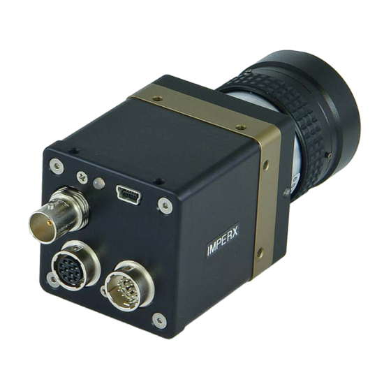
CAMERA CONNECTIVITY 1.4.1. HD-SDI Output The interface between the BOBCAT HD-SDI camera and outside equipment is done via 3 connectors and one LED, located on the back panel of the camera – Figure 1.8. 1. Camera output – standard HD-SDI BNC output 2. -
Page 29: Figure 1.9 - Hd-Sdi Camera Power Connector Pin-Outs (Rear View)
BOBCAT HD-SDI Hardware User’s Manual the external trigger input (black) and strobe output (white). BNC pin mapping is shown in Table 1.7. Signal Cable color Description Case In 1 Return User Selectable Input 1 Return BNC Black Signal In 1 Active... -
Page 30: Figure 1.10 - Hd-Sdi Camera Serial/Lens Control Pin-Outs (Rear View)
BOBCAT HD-SDI Hardware User’s Manual The female 12-pin HIROSE connector provides Camera Control via an RS232 serial interface and outputs Lens Control signals for Zoom, Focus, and Iris for a standard Type 1 (6V) or Type 5 (12V) C-Mount motorized lens. Refer to Fig 1.10 for connector pin-outs. -
Page 31: Power Supply
Hardware User’s Manual 1.4.2. Power Supply The Bobcat HD-SDI camera can be powered using a universal desktop power supply adapter providing +12VDC, ± 10%, and up to 2.5A constant DC current. A universal power supply adapter is available (for an additional price) from Imperx for all Bobcat HD-SDI camera models. -
Page 32: Mechanical, Optical And Environmental
BOBCAT HD-SDI Hardware User’s Manual 1.5. MECHANICAL, OPTICAL and ENVIRONMENTAL 1.5.1. Mechanical The camera housing is manufactured using high quality zinc-aluminum alloy and anodized aluminum. For maximum flexibility the camera has twelve (12) M3X0.5mm mounting, located towards the front and the back. An additional plate with ¼-20 UNC (tripod mount) and hardware is shipped with each... -
Page 33: Figure 1.12 - Dimensional Drawings For The Sdi-B1920M, B1920C
BOBCAT HD-SDI Hardware User’s Manual Figure 1.12 – Dimensional drawings for the SDI-B1920M, B1920C. Imperx, Inc. Rev. 1.4 6421 Congress Ave. 6/2/2014 Boca Raton, FL 33487 +1 (561) 989-0006 33 of 175... - Page 34 BOBCAT HD-SDI Hardware User’s Manual Figure 1.13 – Dimensional drawings for SDI-B1320M, B1320C, B1921M, B1921C, B1922M, B1922C, B1923M, B1923C. Imperx, Inc. Rev. 1.4 6421 Congress Ave. 6/2/2014 Boca Raton, FL 33487 +1 (561) 989-0006 34 of 175...
-
Page 35: Optical
– illustrated in Figure 1.15 and Figure 1.16. An F-mount lens can be used with a C-mount camera via an F-mount to C-mount adapter, which can be purchased separately – refer to the Imperx web site for more information. The camera performance and signal to noise ratio depends on the illumination (amount of light) reaching the sensor and the exposure time. -
Page 36: Figure 1.15 - Optical Plane Position For The Sdi-B1920M, B1920C
BOBCAT HD-SDI Hardware User’s Manual 1. Avoid direct exposure to a high intensity light source (such as a laser beam). This may damage the camera optical sensor! 2. Avoid foreign particles on the surface of the imager. Figure 1.15 – Optical plane position for the SDI-B1920M, B1920C. -
Page 37: Figure 1.16 - Optical Plane Position For The Sdi-B1320M, B1320C, B1921M, B1921C, B1922M, B1922C, B1923M, B1923C
BOBCAT HD-SDI Hardware User’s Manual Figure 1.16 – Optical plane position for the SDI-B1320M, B1320C, B1921M, B1921C, B1922M, B1922C, B1923M, B1923C. Note: DATUM “A” REFERS TO THE IMAGING PLANE (TOP OF IMAGING OF SENSORS: KAI- 2150/1150) Imperx, Inc. Rev. 1.4 6421 Congress Ave. -
Page 38: Environmental
BOBCAT HD-SDI Hardware User’s Manual 1.5.3. Environmental The camera is designed to operate from -40 to 85 C in a dry environment. The relative humidity should not exceed 80% non-condensing. Always keep the camera as cool as possible. Always allow sufficient time for temperature... -
Page 39: Chapter 2 - Camera Features
BOBCAT HD-SDI Hardware User’s Manual 2. Chapter 2 – Camera Features Camera Features This chapter discusses the camera’s features and their use. Imperx, Inc. Rev. 1.4 6421 Congress Ave. 6/2/2014 Boca Raton, FL 33487 +1 (561) 989-0006 39 of 175... -
Page 40: Normal Mode - Dual Output
BOBCAT HD-SDI Hardware User’s Manual Normal Mode – Dual Output 2.1. When operating in a dual output mode, the image is split in two equal parts, each side consisting of half of the horizontal pixels and the full vertical lines. -
Page 41: External Frame Time Control
BOBCAT HD-SDI Hardware User’s Manual Frame rate [fps] = 1 / read-out time [sec] (1.1) The user can program the camera to run slower than the nominal speed preserving the camera full resolution. The user can independently extend the camera frame time (the time required to read the entire frame out of the CCD imager). -
Page 42: Figure 2.2 - Horizontal And Vertical Window Positioning
BOBCAT HD-SDI Hardware User’s Manual Figure 2.2 – Horizontal and vertical window positioning. Slave AOIs AOI1 to AOI6 are assigned as slave AOIs and they MUST be selected so they are completely inside MAOI. All slave AOIs can be set independently with no restrictions for overlapping and order –... -
Page 43: Exposure Control
BOBCAT HD-SDI Hardware User’s Manual Processing AOI (PAOI) All AOIs are functionally equal except PAOI. PAOI can be enabled as LUT or image processing Region of Interest (ROI). When enabled as LUT ROI, the LUT function will apply only to the selected ROI, all data outside of the region will not be processed with the LUT function. -
Page 44: Programmable Frame Time
BOBCAT HD-SDI Hardware User’s Manual Frame Time Exposure VCCD SHUTTER Figure 2.5 – Electronic shutter position. 2.4.2. Programmable Frame Time Variable frame time mode provides the ability to run the camera in full resolution but at a slower frame rate than the nominal camera frame resulting in increased exposure time for the frame. -
Page 45: Automatic Exposure Control (Aec)
BOBCAT HD-SDI Hardware User’s Manual 2.4.3. Automatic Exposure Control (AEC) The camera can be set to automatic exposure (and gain) control in order to keep the same image brightness during changing light conditions. Both modes – automatic exposure and automatic gain can be enabled simultaneously. In this mode the user sets the image brightness (luminance) to be maintained, and the camera adjusts the exposure accordingly. -
Page 46: Gain And Offset
BOBCAT HD-SDI Hardware User’s Manual camera timing has a flag for odd and even frames. Each strobe can be assigned to every frame, only odd frames, only even frames, or the strobe can be disabled. The actual strobe signal can be mapped to the corresponding camera outputs – please refer to the “I/O Control”... -
Page 47: Digital Domain - Manual Control
BOBCAT HD-SDI Hardware User’s Manual signal output level and gain/offset. Theoretically, the black level should reside at 0 volts and the gain changes should only lead to increasing the amplitude of the video signal. Since the camera has two separate video outputs coming out of the CCD, there is always some offset misbalance between the video outputs. -
Page 48: Data Output Format
BOBCAT HD-SDI Hardware User’s Manual the preset by the user min-max limits. If one of the gain limits has been reached, the camera indicates the limit has been reached and keeps the value until the light condition change. The speed of convergence (how fast the camera stabilizes after change), can be preset by the user (four possible options are available). -
Page 49: Pulse Generator
BOBCAT HD-SDI Hardware User’s Manual 2.8. PULSE GENERATOR The camera has a built in pulse generator. The user can program the camera to generate a discrete sequence of pulse or a continuous trail – Figure 2.9. The pulse generator can be used as a trigger signal, or can be mapped to one of the outputs –... -
Page 50: I/O Control
Odd/Even Frame Flag Pulse Generator Strobe One Strobe Two Table 1.12 – BOBCAT HD-SDI Output Mapping. Imperx, Inc. Rev. 1.4 6421 Congress Ave. 6/2/2014 Boca Raton, FL 33487 +1 (561) 989-0006 50 of 175... -
Page 51: Electrical Connectivity
Electrical Connectivity Inputs IN1 The external inputs in BOBCAT HD-SDI cameras are directly connected to the camera hardware – Figure 2.10 and Figure 2.11. The input signals “Signal” and “Return” are used to connect to an external Input to the outside source. For IN1 the signal level (voltage difference between the inputs “Signal”... -
Page 52: Test Image Patterns
BOBCAT HD-SDI Hardware User’s Manual Lens Control Output for Iris, Focus, and Zoom The external Lens Control outputs in BOBCAT HD-SDI cameras are directly connected to the camera hardware, and operate in 6 or 12 volts. The maximum average output current... -
Page 53: Image Superimposition
BOBCAT HD-SDI Hardware User’s Manual configured. Please note that the test image patterns do not exercise and verify the CCD’s functionality. The following test images are available: Black – displays black image (value x0000) Gray – displays an uniform dark gray image (value x2000) White –... -
Page 54: White Balance
BOBCAT HD-SDI Hardware User’s Manual 2.11. WHITE BALANCE 2.11.1. White Balance The color representation in the image depends on the color temperature of the light source. Bobcat has built in algorithm to compensate for this. When white balance correction is enabled, the camera collects the luminance data for each of the primary colors R, G and B, analyzes it, and adjusts the color setting in order to preserve the original colors and make white objects to appear white. -
Page 55: Transfer Function Correction - Lut
BOBCAT HD-SDI Hardware User’s Manual reached. The selection to use static or dynamic balancing depends on the application. Please note, that if AGC is enabled, it is strongly recommended to use static balancing, because the dynamic balancing can interfere with the AGC algorithm. -
Page 56: User Defined Lut
BOBCAT HD-SDI Hardware User’s Manual same is valid if the brightness is increased. This is because the display has a nonlinear transfer function and a brightness dynamic range much lower than the camera. The camera has a built-in 8 transfer function to compensate for this non-linearity, which is called gamma correction –... -
Page 57: Defective Pixel Correction
BOBCAT HD-SDI Hardware User’s Manual Modified TF Original TF Input signal Figure 2.15 – Custom LUT. 2.14. DEFECTIVE PIXEL CORRECTION A CCD imager is composed of a two-dimensional array of light sensitive pixels. In general, the majority of the pixels have similar sensitivity. Unfortunately, there are some pixels which sensitivity deviates from the average pixel sensitivity. -
Page 58: Static Pixel Correction
BOBCAT HD-SDI Hardware User’s Manual 2.14.1. Static Pixel Correction Static Defective and Hot pixel correction works with predetermined and preloaded Defective and Hot pixel maps. During factory final testing, our manufacturing engineers run a program specially designed to identify these ‘defective’... -
Page 59: Figure 2.16 - Original Image Showing 'Shading' Effect
When Flat Field Correction is enabled, the camera will use the Flat Field Correction coefficients to compensate for the shading effect. Each Imperx camera is shipped with the Flat Field Correction file that was created for that camera during factory final testing. Users may wish, however, to create their own Flat Field Correction file because of the uniqueness of their operating environment (i.e. -
Page 60: Figure 2.17 - Flat Field Corrected Image
BOBCAT HD-SDI Hardware User’s Manual Figure 2.17 – Flat field corrected image. Imperx, Inc. Rev. 1.4 6421 Congress Ave. 6/2/2014 Boca Raton, FL 33487 +1 (561) 989-0006 60 of 175... -
Page 61: Camera Interface
BOBCAT HD-SDI Hardware User’s Manual 2.16. CAMERA INTERFACE 2.16.1. Status LED The camera has a dual red-green LED, located on the back panel. The LED color and light pattern indicate the camera status and mode of operation: • GREEN is steady ON – Normal operation. The user is expected to see a normal image coming out of the camera. -
Page 62: Current Image Size
BOBCAT HD-SDI Hardware User’s Manual issuing a command – refer to the Exposure Control section. The current camera speed in units of frames per second will be returned. 2.16.5. Current image size The camera image size can change based on a camera feature selected. In any mode of operation (i.e. -
Page 63: Chapter 3 - Digital Image Processing
BOBCAT HD-SDI Hardware User’s Manual 3. Chapter 3 – Digital Image Processing Digital Image Processing This chapter discusses built in Digital Image Processing algorithm in the camera and their implementation and use. Imperx, Inc. Rev. 1.4 6421 Congress Ave. 6/2/2014... -
Page 64: Overview
3.1. OVERVIEW The camera has built-in several basic image processing functions. More functions will be added later. Please contact Imperx for more information. 3.2. IMAGE ENHANCEMENT In many imaging applications the user will have a dark object on a bright background, many dark and bright spots or shadows, or the light will not be sufficient, so the resulting image will have a low contrast, and/or a very low dynamic range. -
Page 65: Figure 3.1 - Original And Processed Image With Single Threshold
BOBCAT HD-SDI Hardware User’s Manual 3.2.1.2. Dual Threshold Binary If the image has a low contrast and does not have well defined dark and bright regions, the simple threshold operation does not yield good results. In such cases a dual (known also as interval or window) thresholding technique has to be implemented –... -
Page 66: Figure 3.2 - Original And Processed Image With Double Threshold
BOBCAT HD-SDI Hardware User’s Manual Figure 3.2 – Original and processed image with double threshold. 3.2.1.3. Dual Threshold with Gray Scale In some low contrast imaging applications, the simple threshold operation along with a superimposed gray scale image might yield a good result. -
Page 67: Multi Point Correction
BOBCAT HD-SDI Hardware User’s Manual if (input signal ≤ X1) Output signal => “BLACK” “Full Gray Scale” if (X1 < input signal < X2) if (input signal ≥ X2) “WHITE” (3.4) Figure 3.3 – Original and processed image with threshold and gray scale stretch. -
Page 68: Figure 3.4 - Single Point Tf Correction
BOBCAT HD-SDI Hardware User’s Manual Input signal Figure 3.4 – Single point TF correction. 3.2.2.2. Multi Point Correction If the image brightness is weighted towards two particular region – dark and bright, and in the same time mid region has a low dynamic range a multi point correction will produce much better results compare to the single point correction. -
Page 69: Figure 3.5 - Multi Point Tf Correction
Figure 3.6 – Multi point image correction (a – original, b – processed). CAUTION NOTE Due to space limitations in the camera FPGA, the “Image processing” module is disabled for the color Bobcat cameras. For more information please contact Imperx. Imperx, Inc. Rev. 1.4 6421 Congress Ave. -
Page 70: Convolution
BOBCAT HD-SDI Hardware User’s Manual 3.3. CONVOLUTION Monochrome Cameras applies a 3 x 3 area filter for the RAW output. Color cameras apply a 3 x 3 area filter for the RGB output. The center pixel and eight surrounding pixels are multiplied by the corresponding filter coefficient, and added together. The result is brightness of the central pixels. -
Page 71: Chapter 4 - Camera Configuration
BOBCAT HD-SDI Hardware User’s Manual 4. Chapter 4 – Camera Configuration Camera Configuration This chapter discusses how to communicate with the camera and configure the camera’s operating parameters. Imperx, Inc. Rev. 1.4 6421 Congress Ave. 6/2/2014 Boca Raton, FL 33487... -
Page 72: Overview
Hardware User’s Manual 4.1. OVERVIEW The Bobcat HD-SDI series of cameras are highly programmable and flexible. All of the cameras resources (internal registers, video amplifiers and parameter FLASH) can be controlled by the user. The user communicates with the camera using a simple, register-based, command protocol via the Camera’s RS-232 serial interface. -
Page 73: Camera Serial Protocol
BOBCAT HD-SDI Hardware User’s Manual 4.2.2. Camera Serial Protocol In order to access the camera registers and resources a sequence of bytes needs to be transmitted to the camera via the Camera’s RS-232 serial interface. This is an RS-232, asynchronous, full-duplex, serial protocol, with 1 start bit, 8 data bits, 1 stop bit, no hand shake, and no parity –... -
Page 74: Figure 4.2 - Normal Write Cycle
BOBCAT HD-SDI Hardware User’s Manual Wr_Cmd Data Addr Figure 4.2 – Normal write cycle. Write Not-acknowledge (2 Bytes): <Nak> <Error Code> byte: 0x15 (Not-acknowledge) byte: <XX> (Nck Error Code. See Error Code Description section) These characters are dropped * * * *... -
Page 75: Figure 4.5 - Normal Read Cycle
BOBCAT HD-SDI Hardware User’s Manual In order to read from any given camera register, a sequence of 3 bytes should be sent to the camera. If there is no error the camera returns 5 bytes – one byte acknowledge for the read command <Ack> and four bytes of data <DD>... -
Page 76: Camera Configuration Register Description
BOBCAT HD-SDI Hardware User’s Manual x01 – Invalid command. An invalid command (not 52 or 57) has been sent to the camera. x02 – Time-out. x03 – Checksum error x04 – Value less then minimum x05 – Value higher than maximum x06 –... - Page 77 BOBCAT HD-SDI Hardware User’s Manual ‘boot from’ value from non-volatile memory and loads the appropriate configuration space. Address 0x6000 Data (1- 0) 00 – Boot from Factory 01 – Boot from User #1 10 – Boot from User #2 Data (31- 2) 4.3.2.2.
-
Page 78: Retrieving Manufacturing Data
BOBCAT HD-SDI Hardware User’s Manual Address 0x6074 4.3.2.7. Save to User #2 command instructs the camera to save its ‘Save To User #2’ workspace to the user #2 space. All current workspace settings will be saved to the user #2 space. This is a command, not a register. The act of writing to this location initiates the save to user #2 space. - Page 79 BOBCAT HD-SDI Hardware User’s Manual Data (31:28) : <FW image> Data (27:24) : <CCD Type> Data (23:0) : <FW revision> I/O FW revision Address : 0xE004 Data (31:28) : <I/O FW image> Data (27:24) : Reserved Data (23:0) : <I/O FW revision>...
-
Page 80: Camera Information Registers
BOBCAT HD-SDI Hardware User’s Manual This register returns the camera date of manufacture – The complete date of manufacture is 2 registers. Address 0x7024, 0x7028 Data <Date of Manufacture> 4.3.3.7. Camera Type This register returns the camera type – The complete assembly is 4 registers. - Page 81 BOBCAT HD-SDI Hardware User’s Manual Data (15:0) Data (31- 16) <Minimum Line Time> 4.3.4.5. Current Minimum Exposure This register returns the current minimum possible camera exposure time in Address 0x6094 Data (23:0) <Minimum Camera Exposure> Data (31:24) 4.3.4.6. Current Maximum Exposure This register returns the current camera maximum exposure time in us.
-
Page 82: Table 1.13 - Current Camera Temperature Values
BOBCAT HD-SDI Hardware User’s Manual This register returns the current analog gain and the current average image luminance during normal, AGC and Tap Balance operation. The Current Analog Gain (register bits D11:D0) displays: The current slider gain for tap 1 during normal operation. -
Page 83: Image Size (Aoi) Workspace Registers
BOBCAT HD-SDI Hardware User’s Manual 4.3.4.12. Tri-Level sync detected format This register returns the detected HD Tri-Level sync format. Address 0x0618 Data (3:0) 0x0 – 1080p@23.98 0x1 – 1080p@24 0x2 – 1080p@25 0x3 – 1080p@29.97 0x4 – 1080p@30 0x5 – 1080i@50 0x6 –... - Page 84 BOBCAT HD-SDI Hardware User’s Manual Data (11:0) <value> AOI 1 offset in horizontal direction Data (31:12) AOI 1 Horizontal Width Address 0x022C Data (11:0) <value> AOI 1 width in horizontal direction Data (31:12) AOI 1 Vertical Offset Address 0x028C Data (11:0) <value>...
- Page 85 BOBCAT HD-SDI Hardware User’s Manual Data (11:0) <value> AOI 2 offset in vertical direction Data (31:12) AOI 2 Vertical Height Address 0x0270 Data (11:0) <value> AOI 2 height in vertical direction Data (31:12) 4.3.5.4. AOI 3 This set of register enables AOI #3 and sets the appropriate window size and offset in horizontal and vertical direction.
- Page 86 BOBCAT HD-SDI Hardware User’s Manual This set of register enables AOI #4 and sets the appropriate window size and offset in horizontal and vertical direction. AOI 4 Enable Address 0x0218 Data (1:0) 00 – AOI 4 disable 01 – AOI 4 include 10 –...
- Page 87 BOBCAT HD-SDI Hardware User’s Manual Data (31:2) AOI 5 Horizontal Offset Address 0x025C Data (11:0) <value> AOI 5 offset in horizontal direction Data (31:12) AOI 5 Horizontal Width Address 0x023C Data (11:0) <value> AOI 5 width in horizontal direction Data (31:12)
-
Page 88: Exposure Control Workspace Registers
BOBCAT HD-SDI Hardware User’s Manual Data (31:12) AOI 6 Vertical Offset Address 0x02A0 Data (11:0) <value> AOI 6 offset in vertical direction Data (31:12) AOI 6 Vertical Height Address 0x0280 Data (11:0) <value> AOI 6 height in vertical direction Data (31:12) 4.3.6. -
Page 89: Aec, Agc, Aic Workspace Registers
BOBCAT HD-SDI Hardware User’s Manual This register sets the actual frame time in microseconds. Address 0x0558 Data (23:0) <value> – actual frame time in micro seconds. Data (31:24) 4.3.7. AEC, AGC, AIC Workspace Registers 4.3.7.1. Auto Exposure Control (AEC) This register enables the auto exposure control. - Page 90 BOBCAT HD-SDI Hardware User’s Manual 11 – 4x speed – fast Data (31:2) 4.3.7.5. Auto Gain Control (AGC) This register enables the auto gain control. Address 0x0154 Data (0) 0 – disable auto gain control 1 – enable auto gain control Data (31:1) 4.3.7.6.
- Page 91 BOBCAT HD-SDI Hardware User’s Manual 4.3.7.9. Luminance Level Threshold This register sets the desired luminance level to be maintained during AEC or AGC process. Address 0x0158 Data (11:0) <value> – desired luminance level Data (31:12) 4.3.7.10. Luminance Type Selection This register sets the luminance mode to be used during AEC or AGC process.
-
Page 92: Video Amp, Gain And Offset Workspace Registers
BOBCAT HD-SDI Hardware User’s Manual Data (11:0) <value> AOI height in vertical direction Data (31:12) 4.3.7.12. Auto Iris Control (AIC) This register enables the auto iris control. Address 0x014C Data (0) 0 – disable auto iris control 1 – enable auto iris control... - Page 93 BOBCAT HD-SDI Hardware User’s Manual 01 – 0.0 dB pre-amplifier gain channel 2 10 – +3.0 dB pre-amplifier gain channel 2 11 – +6.0 dB pre-amplifier gain channel 2 Data (31:2) 4.3.8.5. Analog Gain – Channel 2 This register sets the main analog gain for channel 2.
-
Page 94: Pulse Generator Workspace Registers
BOBCAT HD-SDI Hardware User’s Manual This register enables the tap balance. If the “Tap balance once” is to be used, the register has to be set every time from “00” to “10”. Address 0x0110 Data (1:0) 00 – no tap balance 01 –... -
Page 95: 4.3.1 Test Pattern Workspace Registers
BOBCAT HD-SDI Hardware User’s Manual Data (16) 1 – continuous pulse generation Data (31:17) 4.3.9.5. Pulse Generator Enable This register enables the pulse generator. Address 0x0540 Data (0) 0 – disable pulse generator operation 1 – enable pulse generator operation Data (31:1) 4.3.1 Test Pattern Workspace Registers... - Page 96 BOBCAT HD-SDI Hardware User’s Manual Address 0x0138 Data (11:0) <value> – H1 line position Data (31:12) 4.3.9.8. H2 Superimposed Line Position This register set the position of the horizontal line H2 (bottom) position. Address 0x013C Data (11:0) <value> – H2 line position Data (31:12) 4.3.9.9.
-
Page 97: Input/Output Workspace Registers
BOBCAT HD-SDI Hardware User’s Manual Data (0) 0 – disable Y histogram 1 – enable Y histogram Data (1) 0 – disable RGB histogram 1 – enable RGB histogram Data (2) 0 – disable Frame number 1 – enable Frame number Data (3) 0 –... - Page 98 BOBCAT HD-SDI Hardware User’s Manual 1110 – Software (Bit Toggle) Others – reserved Data (31:4) 4.3.10.3. OUT2 Output Polarity This register sets the polarity (active Low or High) for the OUT2 output. Address 0x0598 Data (0) 0 – active LOW 1 –...
- Page 99 BOBCAT HD-SDI Hardware User’s Manual 11 – enable Strobe #1 even frames only Data (31:2) 4.3.10.6. Strobe #1 Position This register sets the position of the strobe #1 pulse with respect of the end of the frame. Address 0x0568 Data (23:0) <value>...
-
Page 100: Output Data Format
BOBCAT HD-SDI Hardware User’s Manual Data (23:0) <value> – strobe pulse duration in microseconds Data (31:24) 4.3.11. Output Data Format 4.3.11.1. Negative Image Enable This register inverts the image from positive to negative. Address 0x0188 Data (0) 0 – positive image 1 –... -
Page 101: White Balance Workspace Registers
BOBCAT HD-SDI Hardware User’s Manual 0x9 – 720p@59.94 0xA – 720p@60 others - reserved Data (31:4) 4.3.11.4. Tri-Level sync mode This register selects Tri-Level sync mode. Address 0x0614 Data (0) 0x0 – disable 0x1 – genlock Data (31:1) 4.3.11.5. Tri-Level sync shift... - Page 102 BOBCAT HD-SDI Hardware User’s Manual This register selects which auto white balance tracking speed will be used – 1x, 2x, 3x, 4x, and 5x. Address 0x0340 Data (2:0) 000 – 1x; slowest 001 – 2x 010 – 3x 011 – 4x 100 –...
-
Page 103: Color Correction Workspace Registers
BOBCAT HD-SDI Hardware User’s Manual Data (31:12) 4.3.13. Color Correction Workspace Registers 4.3.13.1. Color Matrix Coefficients Crr This register sets the digital gain for Crr. Address 0x0310 Data (0:01) <value>; 000h….7FFh; 1 step 1/256; range – 4.000 … + 3.996... - Page 104 BOBCAT HD-SDI Hardware User’s Manual Color matrix coefficient Cbg This register sets the digital gain for Cbg. Address 0x0330 Data (0:11) <value>; 000h….7FFh; 1 step 1/256; range – 4.000 … + 3.996 Data (31:12) Color matrix coefficient Crb This register sets the digital gain for Crb.
-
Page 105: Data Correction Workspace Registers
BOBCAT HD-SDI Hardware User’s Manual Data (31:11) 4.3.13.4. Offset Blue This register sets the digital offset for Blue. Address 0x0324 Data (10:0) <value>; 000h….7FFh; – 1024 … + 1023 Data (31:11) 4.3.14. Data Correction Workspace Registers 4.3.14.1. User LUT Select This register selects which User LUT will be used. - Page 106 BOBCAT HD-SDI Hardware User’s Manual 001 – Gamma Y = 1.6 010 – Gamma Y = 1.9 100 – Gamma Y = 2.2 101 – Gamma Y = 1/1.3 110 – Gamma Y = 1/1.6 111 – Gamma Y = 1/2.2 Data (31:3) 4.3.14.4.
-
Page 107: Data Processing Register Description
BOBCAT HD-SDI Hardware User’s Manual Address 0x0128 Data (0) 0 – FFC disable 1 – FFC enable Data (31:1) 4.4. DATA PROCESSING REGISTER DESCRIPTION 4.4.1. Image Enhancement Workspace Registers 4.4.1.1. Enhancement Mode Selector This register selects the image enhancement mode of operation. - Page 108 BOBCAT HD-SDI Hardware User’s Manual 4.4.1.5. Point Y2 Position This register selects the position value for point Y2. Address 0x0410 Data (11:0) <value> – point Y2 position value Data (31:12) 4.4.1.6. Processing and LUT AOI (PAOI) This set of register enables the processing and/or LUT AOI and sets the appropriate window size and offset in horizontal and vertical direction.
-
Page 109: Convolution Register
BOBCAT HD-SDI Hardware User’s Manual 4.4.2. Convolution register This set of registers enables the convolution and sets the digital gain for Cxy coefficients. Convolution Enable Address 0x0430 Data (0) 0 – Disable 1 - Enable Data (31:1) C00 coefficient Address... - Page 110 BOBCAT HD-SDI Hardware User’s Manual C12 coefficient Address 0x0448 Data (11:0) <value>; 000h….FFFh; 1 step 1/64; range -32 … + 31.984 Data (31:12) C20 coefficient Address 0x044C Data (11:0) <value>; 000h….FFFh; 1 step 1/64; range -32 … + 31.984 Data (31:12)
-
Page 111: Lens Controller Register Description
BOBCAT HD-SDI Hardware User’s Manual 4.5. LENS CONTROLLER REGISTER DESCRIPTION 4.5.1. Lens Controller Workspace Registers 4.5.1.1. Pulse Width This register sets the lens controller motor pulse width. Address 0x042C Data (3:0) 0x0 – 1 ms 0x1 – 2 ms 0x2 – 4 ms 0x3 –... - Page 112 BOBCAT HD-SDI Hardware User’s Manual 0xFF – maximum speed (GUI, SPD) Data (31:8) 4.5.1.5. Focus Travel Distance This register sets the number of motor control pulses to control focus travel distance. Address 0x041C Data (11:0) 0x001 – min travel distance (GUI,Near) 0xFFF –...
- Page 113 BOBCAT HD-SDI Hardware User’s Manual 4.5.1.8. Iris Speed This register sets the distance between pulses to control iris speed. Address 0x0418 Data (7:0) 0x01 – minimum speed (GUI, SPD) 0xFF – maximum speed (GUI, SPD) Data (31:8) Imperx, Inc. Rev. 1.4 6421 Congress Ave.
-
Page 114: Chapter 5 – Bobcat Configurator
BOBCAT HD-SDI Hardware User’s Manual 5. CHAPTER 5 – Bobcat Configurator BOBCAT Configurator This chapter provides a quick reference to using the BOBCAT HD-SDI Configurator camera configuration utility for BOBCAT HD-SDI series cameras. Imperx, Inc. Rev. 1.4 6421 Congress Ave. -
Page 115: Figure 5.1- Discovery Procedure - Select Port
‘discovering’ and ‘searching’ all available UART components in your PC and allowing the user to select the one that is connected to the Bobcat HD-SDI camera. The Bobcat search engine will search for any available COM port installed on the PC as well. -
Page 116: Figure 5.2 - Hd-Sdi Camconfig Main Gui Window
BOBCAT HD-SDI Hardware User’s Manual 5.3. GRAPHICAL USER INTERFACE After having selected the desired camera, the Bobcat CamConfig Graphical User Interface (GUI) main window will appear – illustrated in Figure 5.2. The GUI Interface is very intuitive and self-explanatory. The basic features are: 1. -
Page 117: Figure 5.3 - Main Menu
If the connection between the camera and the computer is lost a red cross will appear above the connection icon. 5.4. MAIN GUI MENU All panels in the Bobcat HD-SDI CamConfig share the same general control options and menus for “File”, “View” and “Help” – Figure 5.3. Figure 5.3 – Main Menu. Run Application: Select and starts other executable file (Frame-Grabber application, etc.…) that user normally uses. - Page 118 BOBCAT HD-SDI Hardware User’s Manual File – loads the camera registers from a saved configuration file Workspace – updates the GUI with the current camera workspace settings Factory – loads the camera registers with the original (factory) settings. User Space #1 – loads the camera registers with a saved camera settings in the user space 1.
-
Page 119: Figure 5.4 - Defective Pixel Map
BOBCAT HD-SDI Hardware User’s Manual Figure 5.4 – Defective pixel map. Dead Pixels – pixels with sensitivity that deviates more than 15% due to fluctuations in the CCD manufacturing process. Hot Pixels – pixels that during normal camera operation are normal, but in long integration modes (programmable frame time) behave as high-intensity bright pixels. -
Page 120: Figure 5.5 - Command Terminal
BOBCAT HD-SDI Hardware User’s Manual Figure 5.5 – Command terminal. Download Terminal – One of the great features in Bobcat configuration utility is download terminal. User can upgrade the camera firmware and up-load to the camera any custom LUT, DPM or FFC – Figure 5.6. -
Page 121: Figure 5.6 - Download Terminal
BOBCAT HD-SDI Hardware User’s Manual Figure 5.6 – Download terminal. Download Procedure: 1. Select correct ‘File Type” before downloading. Several options are possible: DPM, HPM, LUT1, LUT2, Application FW, Application FW 1/O, Register space. 2. Type in or select the correct data file of this feature in ‘File Path’... -
Page 122: Figure 5.7 - View Gui Windows
BOBCAT HD-SDI Hardware User’s Manual 5.5. VIEW GUI WINDOWS The ‘View’ menu allows the user to select which camera parameter window to be displayed on the main CamConfig GUI window – Figure 5.7. Figure 5.7 – View GUI Windows Video Amplifier: Controls the camera analog and digital gain and offset, tap balancing, black level correction. -
Page 123: Figure 5.8 - Help Menu
BOBCAT HD-SDI Hardware User’s Manual Processing: Enables the built-in basic image processing functions. Color: Sets the gain and offset for the primary R G B colors. Sets the white balance mode. Displays WBC values. Data Out (Settings): Sets for the data format – output format, DPC, HPC, FFC controls. -
Page 124: Figure 5.9 - About Camconfig
BOBCAT HD-SDI Hardware User’s Manual Figure 5.9 – About CamConfig. 5.7. PARAMETER WINDOWS Bobcat Cameras have many features that can easily be programmed using the Bobcat graphical user interface (GUI) or via simple register commands using the Command Terminal. The main parameter windows are described below. -
Page 125: Figure 5.11- I/O Control Parameter Window
BOBCAT HD-SDI Hardware User’s Manual Analog: The user can set the desired analog gain (0 to 36 dB, 1024 discrete values) and offset (0 to 1023, 1 step increment) for each channel via the sliders or by entering the desired values. - Page 126 BOBCAT HD-SDI Hardware User’s Manual Output: The user can map each of the camera outputs to OUT1, OUT2. 11 signals are available for mapping. For each input the user can set the signal level to active “High” or active “Low”.
-
Page 127: Figure 5.12 - Pulse Generator Window
BOBCAT HD-SDI Hardware User’s Manual 5.7.3. Pulse Generator In this window the user can configure the parameters of the Internal Pulse Generator – Figure 5.12. Figure 5.12 – Pulse generator window. Granularity: Sets the granularity for the internal counters. Granularity can be set to 1x, 10x, 100x or 1000x. -
Page 128: Figure 5.13 - Exposure Control Window
BOBCAT HD-SDI Hardware User’s Manual 5.7.4. Exposure This window controls the camera exposure, line and frame time, AEC, AGC and AIC modes of operation – Figure 5.13. Figure 5.13 – Exposure control window. Exposure Control: Sets the camera exposure: 1. Off – no exposure control. - Page 129 BOBCAT HD-SDI Hardware User’s Manual 5. Exposure Wheel Degrees slider – sets the actual camera exposure in degres exposure in microseconds. The minimum exposure in degrees. The minimum exposure adjusts accordingly, based on the camera mode of operation. The slider can only be used when “Manual” mode is enabled.
-
Page 130: Test Image
BOBCAT HD-SDI Hardware User’s Manual 1. Average – the average value of the image luminance will be used in the comparison algorithm. 2. Peak – the peak luminance value (maximum luminance level) will be used in the comparison algorithm. Exposure – sets the maximum/minium exposure time, which can be reached in the AEC mode in order to avoid motion smear if a fast moving object is monitored. -
Page 131: Figure 5.14 - Test Image Window
BOBCAT HD-SDI Hardware User’s Manual 9. Vertical Bars – displays a set of 8 vertical gray bars with different gray levels. 10. Y/RGB Histogram – displays separate Y,RGB histogram image. 11. SMPTE Color Bars – displays and HD SMPTE color bar test pattern image. -
Page 132: Figure 5.15 - Aoi Window
BOBCAT HD-SDI Hardware User’s Manual H&V Lines – superimposes a pair of H and/or V lines. Dual sliders are available to select the horizontal and vertical position of the lines. Each line location will be visible in the gray square window. The sliders range from 1 to the maximum number of pixels/lines available on the sensor. -
Page 133: Figure 5.16 - Strobe Control Window
BOBCAT HD-SDI Hardware User’s Manual desired window size by typing the numbers directly, or by selecting the desired size in the provided gray square window. To do this enable the window first, press the corresponding numerical number on the keyboard, and then draw the window with the mouse in the gray square. - Page 134 BOBCAT HD-SDI Hardware User’s Manual a strobe pulse associated with rising edge of the trigger pulse. Standard Strobe: Controls the strobe position and pulse duration for Strobe 1 and Strobe 2. The user can set the individual strobe position relative to the beginning of the frame, via the slider or by entering the desired value.
- Page 135 BOBCAT HD-SDI Hardware User’s Manual Matrix: User sets RGB gain, and offset coefficients. Parameters: Color Matrix slider control of Brightness, Contrast, Saturation, and Hue. White Balance: Sets the White Balance mode of operation. 1. “Off” – No white balance is performed.
-
Page 136: Processing
This window controls the image processing features implemented into the camera. Currently only one Image Enhancement is implemented – Figure 5.18. More features will be added later. Please contact Imperx for more information. This window will be disabled for the color cameras. -
Page 137: Figure 5.18- Processing Window
BOBCAT HD-SDI Hardware User’s Manual Enhancement: are available: Figure 5.18– Processing window. Disable – no enhancement operation will be performed. Single Threshold Binary – single point threshold operation will be performed. Set the desired threshold level X1 using the horizontal (bottom) slider (left portion). -
Page 138: Figure 5.19 - Data Output Window
BOBCAT HD-SDI Hardware User’s Manual using the horizontal (bottom) slider (left portion). Set the desired Y1-point level using the vertical (side) slider (bottom portion). Two Point Correction – two-point image enhancement operation will be performed. Set the desired X1-point level using the horizontal (bottom) slider (left portion), and X2- point –... -
Page 139: Figure 5.20 - Lens Control Window
BOBCAT HD-SDI Hardware User’s Manual DPC – enables Defective Pixel Correction (DPC). Each HD-SDI camera comes with a built-in Defective Pixel Map (DPM) to correct for defective pixels. The user can upload a custom DPM. HPC – enables Hot Pixel Correction (HPC). Each HD-SDI camera comes with a built-in Hot Pixel Map (HPM) to correct for hot pixels. - Page 140 BOBCAT HD-SDI Hardware User’s Manual Zoom Buttons: << Sets full travel (4095 pulses) in Wide direction. >> Sets full travel (4095 pulses) in Narrow direction. < Sets Entry Window value in Wide direction > Sets Entry Window value in Narrow direction.
-
Page 141: Congress Ave. 6/2/2014 Boca Raton, Fl
BOBCAT HD-SDI Hardware User’s Manual Voltage: Sets motor driver pulse voltage to 6 or 12 volts. Imperx, Inc. Rev. 1.4 6421 Congress Ave. 6/2/2014 Boca Raton, FL 33487 +1 (561) 989-0006 141 of 175... -
Page 142: Chapter 6 – Bobcat Warranty And Support
BOBCAT HD-SDI Hardware User’s Manual 6. Chapter 6 – Bobcat Warranty and Support Warranty BOBCAT and Support This chapter discusses the camera’s warranty and support. Imperx, Inc. Rev. 1.4 6421 Congress Ave. 6/2/2014 Boca Raton, FL 33487 +1 (561) 989-0006... -
Page 143: Ordering Information
Visit our Web Site: www.imperx.com 6.3. WARRANTY Imperx warrants performance of its products and related software to the specifications applicable at the time of sale in accordance with Imperx’s standard warranty, which is 2 (two) Imperx, Inc. Rev. 1.4 6421 Congress Ave. 6/2/2014... -
Page 144: Imperx, Inc. Rev. 1.4
This camera has been tested and complies with the limits of Class A digital device, pursuant to part 15 of the FCC rules. Copyright © 2013 Imperx Inc. All rights reserved. All information provided in this manual is believed to be accurate and reliable. No responsibility is assumed by Imperx for its use. -
Page 145: Appendix A – Camera Configuration Reference
BOBCAT HD-SDI Hardware User’s Manual Appendix A – Camera Configuration Reference Camera Configuration Reference This appendix provides a quick reference to the camera configuration workspace registers. Imperx, Inc. Rev. 1.4 6421 Congress Ave. 6/2/2014 Boca Raton, FL 33487 +1 (561) 989-0006... -
Page 146: A.0 Abbreviations
BOBCAT HD-SDI Hardware User’s Manual ABBREVIATIONS RW – read/write, RO – read only, WO – write only – Max. and Min. horizontal image size – camera MAX_HRZ_SZE, MIN_HRZ_SZE dependent – Max. and Min. vertical image size – camera MAX_VER_SZE, MIN_VER_SZE dependent Minimum Line time –... -
Page 147: A.3 Image Size (Aoi) Registers
BOBCAT HD-SDI Hardware User’s Manual 0x6084 Vertical Frame Size <MAX_VER_SZE, MIN_VER_SZE> 0x6088 Current Minimum Frame Time <FRM_TIM_MIN> 0x608C Current Minimum Line Time <LIN_TIM_MIN> , <CLK_PER_PSC> 0x6090 Current Maximum Exposure <FRM_TIM_ACT> 0x6094 Current Minimum Exposure <FRR_EXP_MIN> 0x6098 Current Frame Number <Current Frame Number>... -
Page 148: A.4 Exposure Control Registers
BOBCAT HD-SDI Hardware User’s Manual 0x0254 AOI 3 Horizontal Offset <Offset Value> 0x00000000 MAX_HRZ_SZE - 1 0x0258 AOI 4 Horizontal Offset <Offset Value> 0x00000000 MAX_HRZ_SZE - 1 0x025C AOI 5 Horizontal Offset <Offset Value> 0x00000000 MAX_HRZ_SZE - 1 0x0260 AOI 6 Horizontal Offset <Offset Value>... -
Page 149: A.6 Aec, Agc, Aic Registers
BOBCAT HD-SDI Hardware User’s Manual 00 - -3dB, 01 - 0dB, 0x0010 PreAmp Gain Ch. 2 0x00000000 0x00000003 10 - +3db, 11 - +6db 0x0014 Analog Gain Ch. 2 <Analog Gain Value> 0x00000000 0x000003FF 0x0018 Analog Offset Ch. 2 <Analog Offset Value>... -
Page 150: A.7 Trigger Registers
BOBCAT HD-SDI Hardware User’s Manual TRIGGER REGISTERS Register Name Type Usage MIN Value MAX Value Address 0x00 - Off, 0x10 – Tri-Level 0x0584 Tri-Level sync mode 0x00000000 0x00000010 mode 0x0528 Tri-Level sync shift <Tri-Level sync shift of PCLK> 0x00000000 0x000003FF... -
Page 151: A.10 Strobe Registers
BOBCAT HD-SDI Hardware User’s Manual A.10 STROBE REGISTERS Address Register Name Type Usage MIN Value MAX Value 00 - Off, 01 - Each, 0x055C Strobe 1 mode selector 0x00000000 0x00000003 10 - Odd, 11 - Even 00 - Off, 01 - Each,... -
Page 152: A.13 Wb And Color Correction Registers
BOBCAT HD-SDI Hardware User’s Manual A.13 WB AND COLOR CORRECTION REGISTERS Address Register Name Type Usage MIN Value MAX Value 0x0300 Auto White Balance 00 - Off, 01 - Once, 0x00000000 0x00000005 Mode 10 - Auto, 11 – Manual, 100 – Indoor 3200K, 101 –... -
Page 153: A.15 Processing Registers
BOBCAT HD-SDI Hardware User’s Manual 1/2.2 0x0120 Defective Pixel Correction RW 1 - Enable, 0 - Disable 0x00000000 0x00000001 00 – Disable, 01 – Static, 0x0124 Hot Pixel Correction 0x00000000 0x00000003 10 – Dynamic, 11 - All 00 – Disable, 01 – Static,... -
Page 154: A.17 Enhancement 3 X 3 Filter Registers
BOBCAT HD-SDI Hardware User’s Manual 0x0418 Iris Speed Slider Control Iris Speed 0x00000001 0x000000FF 0x041C Focus Travel Slider Focus Near/Far 0x00000001 0x00000FFF 0x041C Focus Near Focus Near 0x00010001 0x00010FFF 0x041C Focus Far Focus Far 0x00020001 0x00020FFF 0x041C Focus Near Full... -
Page 155: A.18 Manufacturing Data Registers
BOBCAT HD-SDI Hardware User’s Manual A.18 MANUFACTURING DATA REGISTERS Register Name Type Value Address 0x7004 Assembly Part Number <Assembly Part Number_1> 0x7008 Assembly Part Number <Assembly Part Number_2> 0x700C Assembly Part Number <Assembly Part Number_3> 0x7010 Assembly Part Number <Assembly Part Number_4>... -
Page 156: Appendix B – Creating Look Up Tables
BOBCAT HD-SDI Hardware User’s Manual Appendix B – Creating Look Up Tables Creating Look Up Tables This appendix provides a reference on how to create a lookup table using the ASCII editor, Excel spreadsheet, and IpxToolkit: Lut Manager SW. Imperx, Inc. -
Page 157: B.1 Overview
BOBCAT HD-SDI Hardware User’s Manual OVERVIEW The Lookup Table file can be created using any standard ASCII text editor or by using Microsoft Excel. Additionally, any spreadsheet or mathematical program capable of generating a comma delimited (.csv) file can be used. - Page 158 BOBCAT HD-SDI Hardware User’s Manual The format of the .LUT file for color camera is as follows: -- Look Up Table input file example, -- lines beginning with two dashes are comments, -- and are ignored by parser, :Header, -- this is the text that will get displayed with a 'glh'...
-
Page 159: B.3 Using Microsoft Excel
BOBCAT HD-SDI Hardware User’s Manual USING MICROSOFT EXCEL The .LUT file can be created in Excel as follows: 1 - create the spreadsheet as shown below (note that 1024 (1024*3) rows are required in the table). 2 - add the necessary equations into the output cells to generate the transfer function required. - Page 160 BOBCAT HD-SDI Hardware User’s Manual USING LUT Manager The .LUT file can be created in LUT Manager. The LUT manager is a plugin Of IpxToolkit SW. Please refer to the IpxToolkit documentation. Imperx, Inc. Rev. 1.4 6421 Congress Ave. 6/2/2014...
- Page 161 BOBCAT HD-SDI Hardware User’s Manual Appendix C – Creating DPC and HPC Tables Creating DPC and HPC Tables This appendix provides a reference on how to create a DPC and HPC table using an ASCII editor, and the IpxToolkit DPC/HPC Utility.
- Page 162 BOBCAT HD-SDI Hardware User’s Manual OVERVIEW The Defective Pixel Map (DPM) and Hot Pixel Map (HPM) are provided with each camera. If the user wants to create its own DPM or HPM file, he/she can use any standard ASCII text editor or Microsoft Excel. Additionally, any spreadsheet or mathematical program capable of generating a comma delimited (.csv) file can be...
- Page 163 BOBCAT HD-SDI Hardware User’s Manual USING AN IPXTOOLKIT DPC/HPC UTILITY The .dpm/.hpm files can be created in IpxToolkit DPC/HPC Utility. Please refer to the IpxToolKit documentation. Imperx, Inc. Rev. 1.4 6421 Congress Ave. 6/2/2014 Boca Raton, FL 33487 +1 (561) 989-0006...
-
Page 164: Congress Ave. 6/2/2014 Boca Raton, Fl
BOBCAT HD-SDI Hardware User’s Manual Appendix D – Software Installation Software Installation This appendix explains how to install the Bobcat CamConfig software. Imperx, Inc. Rev. 1.4 6421 Congress Ave. 6/2/2014 Boca Raton, FL 33487 +1 (561) 989-0006 164 of 175... - Page 165 BOBCAT HD-SDI Hardware User’s Manual Use the following steps to install the BobCat Configurator software supplied on a CD. Note that ‘click’ refers to the left mouse button. 1. If a version of BobCat Configurator was previously installed on this machine, then you...
-
Page 166: Firmware Upgrade
BOBCAT HD-SDI Hardware User’s Manual Appendix E – Firmware Upgrade Firmware Upgrade This appendix explains how to upgrade the Bobcat Firmware, DPH, HPM, FFC, LUT and camera registers for Bobcat HDSDI cameras. Imperx, Inc. Rev. 1.4 6421 Congress Ave. 6/2/2014... - Page 167 To receive the latest FW and RGS files, please contact Imperx. The FW of HD-SDI camera consists of two parts: Application Firmware and I/O Application Firmware.
- Page 168 BOBCAT HD-SDI Hardware User’s Manual RGS Upgrade: When you select the appropriate Factory Space file for this particular camera you have to press button “Load File” and wait to finish the process of uploading. This could take few minutes. When everything is done you should get the message “Uploading is finished successfully”.
-
Page 169: Imperx, Inc. Rev. 1.4
BOBCAT HD-SDI Hardware User’s Manual Figure E.3 Figure E.4 Imperx, Inc. Rev. 1.4 6421 Congress Ave. 6/2/2014 Boca Raton, FL 33487 +1 (561) 989-0006 169 of 175... - Page 170 BOBCAT HD-SDI Hardware User’s Manual BOBCAT HD-SDI UPGRADE USING BOBCAT UPLOAD MANAGER The user can upload FW, LUT, HPC, DPC, FFC by Bobcat Upload Manager. Please refer to the Bobcat Upload Manager documentation. Imperx, Inc. Rev. 1.4 6421 Congress Ave.
-
Page 171: Imperx, Inc. Rev. 1.4
If the upgrade process cannot be completed, the camera will power with the default Factory Firmware so you can start the upgrade process again. If you need more information, please contact Imperx. If the user selects to upgrade camera firmware and camera factory register space, the camera firmware must be upgraded first. - Page 172 BOBCAT HD-SDI Hardware User’s Manual Appendix G – Power Supplies Powers Supply This appendix has power supply models and cameras for Bobcat HD-SDI series cameras. Imperx, Inc. Rev. 1.4 6421 Congress Ave. 6/2/2014 Boca Raton, FL 33487 +1 (561) 989-0006...
-
Page 173: Imperx, Inc. Rev. 1.4
BOBCAT HD-SDI Hardware User’s Manual Model: PS12V04 Bobcat standard power supply ordered separately. Trigger & Strobe pigtail with Male BNC connectors Imperx, Inc. Rev. 1.4 6421 Congress Ave. 6/2/2014 Boca Raton, FL 33487 +1 (561) 989-0006 173 of 175... -
Page 174: Table 1.14 - Auto Iris 4 Pin Mini Plug E4-191J
BOBCAT HD-SDI Hardware User’s Manual Model: PS12V05 Auto Iris 4 pin Video Type Option power supply ordered separately. P4 CON4PF: 4 pin MINI plug E4-191J Signal Type Cable Description IRIS + 12 VDC Power + 12 VDC Main Power @ 1A Max... -
Page 175: Imperx, Inc. Rev. 1.4
BOBCAT HD-SDI Hardware User’s Manual Power Supply Specs: Cable length: Supplied AC power input cable (IEC): 1.8m (6’) 100 - 240 Vac, 50 - 60Hz 1A Power supply Output (+12V): 3m (10’) ± 15cm (6”) connector HIROSE #HR10A-10P-12S Strobe & Trigger: 10cm (4”) ± 1cm (0.5”) connector BNC male Auto Iris Option: 18cm (7”) ±...
Need help?
Do you have a question about the bobcat hd-sdi and is the answer not in the manual?
Questions and answers