Sign In
Upload
Manuals
Brands
Imperx Manuals
Digital Camera
LYNX
Imperx LYNX Manuals
Manuals and User Guides for Imperx LYNX. We have
4
Imperx LYNX manuals available for free PDF download: User Manual, Hardware User Manual, Software User Manual
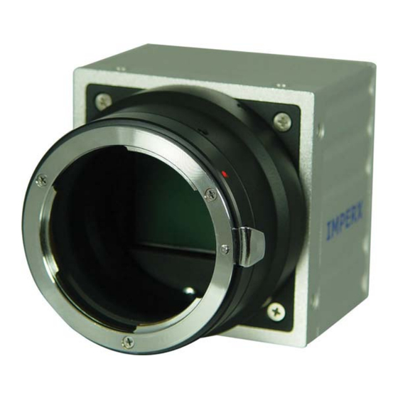
Imperx LYNX User Manual (216 pages)
HIGH-RESOLUTION, FAST, FIELD PGRADEABLE, PROGRAMMABLE, 8/10/12 BIT DIGITAL CAMERAS
Brand:
Imperx
| Category:
Security Camera
| Size: 4.4 MB
Table of Contents
Revision History
2
Table of Contents
3
Chapter 1 - Introduction
14
Lynx Family
15
General Description
17
Lynx Technical Specifications
19
Figure 1.0 - CCD Pixel Structure
19
Figure 1.1 - Spectral Response - Monochrome Quantum Efficiency
20
Table 1.0 - Pixel Structure for Different LYNX Cameras
20
Figure 1.2 - Spectral Response - Color Quantum Efficiency
21
Figure 1.3 - Spectral Response - UV Quantum Efficiency
21
Table 1.1 - Camera Specifications
22
Specifications
23
Camera Connectivity
25
Camera Link Output
25
Figure 1.4 - Camera Back Panel - Camera Link Output
25
Figure 1.5A - Camera Output Connector
25
Table 1.2 - Camera Output Connector - Signal Mapping
26
Table 1.3 - Base Camera Link Bit Assignment
27
Figure 1.5B - Camera Power Connector - Camera Link Output (Viewed from Rear)
28
Table 1.4A - Camera Power Connector Pin Mapping - Camera Link Output
28
Table 1.4B - BNC Connectors Pin Mapping
28
Gige Output
29
Figure 1.6A - Camera Back Panel - Gige Output
29
Figure 1.6B - Camera Power Connector Gige Output (Viewed from Rear)
30
Table 1.5A - Camera Power Connector Pin Mapping - Gige Output
30
Table 1.5B - BNC Connectors Pin Mapping
30
Power Supply
31
MECHANICAL, OPTICAL and ENVIRONMENTAL
32
Mechanical
32
Figure 1.7A - C-Mount Camera Link Cameras - IPX-VGA-L / 1M48-L / 2M30-L / 2M30H -L
32
Figure 1.7B - F-Mount Camera Link Cameras - IPX-4M15-L / 11M5-L / IPX-16M3-L
32
Figure 1.8A - C-Mount Gige Cameras - IPX-VGA-G / 1M48-G / 2M30-G / 2M30H-G
33
Figure 1.8B - F-Mount Gige Cameras - IPX-4M15-G / 11M5-G / 16M3-G
33
Figure 1.9 - Peltier Cooled CL and Gige Cameras - IPX-4M15T / 11M5T / 16M3T
34
Figure 1.10A - IPX-VGA120-L and IPX-VGA210-L Dimensional Drawings
35
Figure 1.10B - IPX-VGA210-G (Silver Body) Dimensional Drawings
36
Figure 1.11A - IPX-1M48-L Dimensional Drawings
38
Figure 1.11B - IPX-1M48-G (Silver Body) Dimensional Drawings
39
Figure 1.12A - IPX-2M30-L and IPX-2M30H-L Dimensional Drawings
41
Figure 1.12B - IPX-2M30-G and IPX-2M30H-G (Silver Body) Dimensional Drawings
42
Figure 1.12C - IPX-2M30-G and IPX-2M30H-G (Black Body) Dimensional Drawings
43
Figure 1.13A - IPX-4M15-L Dimensional Drawings
44
Figure 1.13B - IPX-4M15-G (Silver Body) Dimensional Drawings
45
Figure 1.14A - IPX-11M5-L (Silver Body) Dimensional Drawings
47
Figure 1.14B - IPX-11M5-L (Black Body) Dimensional Drawings
48
Figure 1.14C - IPX-11M5-G (Silver Body) Dimensional Drawings
49
Figure 1.14D - IPX-11M5-G (Black Body) Dimensional Drawings
50
Figure 1.15A - IPX-16M3-L Dimensional Drawings
51
Figure 1.15B - IPX-16M3-G Dimensional Drawings
52
Figure 1.16 - IPX-4M15T/11M5T/16M3T Dimensional Drawings
53
Optical
54
Figure 1.17 - C-Mount and F-Mount Adapter
54
Environmental
55
Chapter 2 - Camera Features
56
Resolution and Frame Rate
57
Single Output
57
Figure 2.1 - Single Output Mode of Operation
57
Table 2.1 - Pixel Structure and Frame Rates
57
Dual Output
58
Figure 2.2 - Dual Output Mode of Operation
58
Center Columns Output (IPX-VGA210-L/G Only)
59
Figure 2.3 - Center Columns Output Mode of Operation
59
Figure 2.4 - Center Columns Output in Dual Mode of Operation
60
Figure 2.5 - Center Columns Output in Dual Tap Mode
60
Timing Diagrams
61
Ipx-Vga120-L, Ipx-Vga210-L/G
61
Figure 2.6 - Single Output Line Timing (IPX-VGA120/210-L and IPX-210-G)
61
Figure 2.7 - Dual Output Line Timing (IPX-VGA210-L/G)
62
Figure 2.8 - Single / Dual (Center) Output Frame Timing (IPX-VGA210-L/G)
62
IPX-VGA210-L/G - Center Columns Operation
63
Figure 2.9 - Center Columns Single Output Line Timing (IPX-VGA210-L/G)
63
Figure 2.10 - Center Columns Dual Output Line Timing (IPX-VGA210-L/G)
63
Ipx-1M48-L/G
64
Figure 2.11 - Single Output Line Timing (IPX-1M48-L/G)
64
Figure 2.12 - Dual Output Line Timing (IPX-1M48-L/G)
64
Figure 2.13 - Single / Dual Output Frame Timing (IPX-1M48-L/G)
65
Ipx-2M30-L/G
66
Figure 2.14 - Single Output Line Timing (IPX-2M30-L/G)
66
Figure 2.15 - Dual Output Line Timing (IPX-2M30-L/G)
66
Figure 2.16 - Single / Dual Output Frame Timing (IPX-2M30-L/G)
67
Ipx-2M30H-L/G
68
Figure 2.17 - Single Output Line Timing (IPX-2M30H-L/G)
68
Figure 2.18 - Dual Output Line Timing (IPX-2M30H-L/G)
68
Figure 2.19 - Single / Dual Output Frame Timing (IPX-2M30H-L/G)
69
Ipx-4M15-L/G
70
Figure 2.20 - Single Output Line Timing (IPX-4M15-L/G)
70
Figure 2.21 - Dual Output Line Timing (IPX-4M15-L/G)
70
Figure 2.22 - Single / Dual Output Frame Timing (IPX-4M15-L/G)
71
Ipx-11M5-L/G
72
Figure 2.23 - Single Output Line Timing (IPX-11M5-L/G)
72
Figure 2.24 - Dual Output Line Timing (IPX-11M5-L/G)
72
Figure 2.25 - Single / Dual Output Frame Timing (IPX-11M5-L/G)
73
Ipx-16M3-L/G
74
Figure 2.26 - Single Output Line Timing (IPX-16M3-L/G)
74
Figure 2.27 - Dual Output Line Timing (IPX-16M3-L/G)
75
Figure 2.28 - Single / Dual Output Frame Timing (IPX-16M3-L/G)
75
Area of Interest
76
Horizontal and Vertical Window
76
Figure 2.29 - Horizontal and Vertical Window Positioning
76
Calculating the Frame Rate Using Vertical Window
77
Table 2.2 - Allowable Horizontal and Window Sizes
77
Figure 2.30 - Frame Rate Vs. Vertical Window Size (IPX-VGA120-L)
78
Ipx-Vga120-L
78
Figure 2.31 - Frame Rate Vs. Vertical Window Size (IPX-VGA210-L/G)
79
Ipx-Vga210-L/G
79
Figure 2.32 - Frame Rate Vs. Vertical Window Size (IPX-1M48-L/G)
80
Ipx-1M48-L/G
80
Figure 2.33 - Frame Rate Vs. Vertical Window Size (IPX-2M30-L/G)
81
Ipx-2M30-L/G
81
Figure 2.34 - Frame Rate Vs. Vertical Window Size (IPX-4M15-L/G)
82
Ipx-4M15-L/G
82
Figure 2.35 - Frame Rate Vs. Vertical Window Size (IPX-11M5-L/G)
83
Ipx-11M5-L/G
83
Figure 2.36 - Frame Rate Vs. Vertical Window Size (IPX-16M3-L/G)
84
Ipx-16M3-L/G
84
Binning
85
Figure 2.37 - Horizontal and Vertical Binning
85
Exposure Control
87
Electronic Shutter
87
Variable Frame Rate - Programmable Integration
87
Figure 2.38 - Electronic Shutter Position
87
Long Integration
88
Figure 2.39 - Programmable Frame Rate
88
Figure 2.40 - Long Integration
89
External Trigger
90
Triggering Inputs
90
Figure 2.41A - Hardware Trigger Electrical Connection - Camera Link Output
90
Figure 2.41B - Hardware Trigger Electrical Connection - Gige Output
91
Standard Triggering - Programmable Exposure
92
Fast Synchronized Triggering - Rapid Capture
93
Figure 2.42 - Standard Triggering Timing
93
Double Exposure Triggering
94
Figure 2.43 - Fast Synchronized Triggering - Rapid Capture
94
Figure 2.44 - Double Exposure Triggering
95
Strobe Output
96
Strobe Positioning
96
Strobe Electrical Connectivity - LYNX with Camera Link Output
96
Figure 2.45 - Strobe Pulse Positioning
96
Figure 2.46A - Strobe Output Electrical Connection (Internal) - Camera Link
97
Figure 2.46B - Recommended External Strobe Output Electrical Connection
97
Camera Link
97
Strobe Electrical Connectivity - LYNX with Gige Output
98
Figure 2.47 - Strobe Output Electrical Connection (Internal) - Gige
98
GAIN and OFFSET
99
Figure 2.48 - AFE Gain and Offset
99
Data Output Format
100
Figure 2.49 - Data Output Format
100
Transfer Function Correction - User Lut
101
Standard Gamma Correction
101
Figure 2.50 - Look up Table
101
User Defined LUT - Examples
102
Figure 2.51 - Gamma Corrected Video Signal
102
Figure 2.52 - Custom LUT
103
Figure 2.53 - Knee Correction
103
Figure 2.54 - Contrast Correction
104
Figure 2.55 - Negative Image
104
Dynamic Signal-To-Noise Correction
107
Figure 2.56 - Dynamic Signal-To-Noise Correction
107
Image Reversal
108
Figure 2.57 - Normal and Mirror Image
108
Negative Image
109
Figure 2.58 - Normal and Negative Image
109
Camera Interface
110
Status LED
110
Temperature Monitor
110
Integration Time Monitor
111
Frame Rate Monitor
111
Test Mode
112
Figure 2.59 - Fixed Pattern #1: Single and Dual Modes
112
Figure 2.60 - Fixed Pattern #2: Single and Dual Modes
112
Automatic Iris Control
113
Defective Pixel Correction
113
Flat Field Correction
114
Figure 2.61 - Original Image Showing 'Shading' Effect
115
Figure 2.62 - Flat Field Corrected Image
115
Thermo-Electric Cooling ( Tec )
116
Chapter 3 - Camera Configuration
117
Overview
118
Configuration Memory
119
Command Format
120
Command Help
121
Startup Procedure
122
Saving and Restoring Settings
123
Set Boot from ( 'Sbf' )
123
Get Boot from ( 'Gbf' )
123
Load from Factory ( 'Lff' )
123
Load from User ( )
124
Save to Factory ( 'Stf' )
124
Save to User ( 'Stu' )
124
Retrieving Manufacturing Data
125
Get Manufacturing Data ( 'Gmd' )
125
Get Assembly Number ( 'Gan' )
125
Get Model Number ( 'Gmn' )
125
Get Firmware Version ( 'Gfv' )
125
Get Software Version
126
Command Description
127
Horizontal Window
127
Vertical Window
128
Shutter Time
129
Long Integration
130
Strobe Position
131
Analog Gain
132
Analog Offset
133
Sao' )
133
Get Analog Offset ( 'Gao' )
133
Dual Tap Mode
134
Set Dual Mode ( 'Sdm' )
134
Get Dual Mode ( 'Gdm' )
134
Bit Depth
135
Get Bit Depth ( 'Gbd' )
135
Lookup Table Operation
136
Set Lookup Table
136
Noise Correction Processing
137
Set Noise Correction
137
Get Noise Correction
137
Horizontal Mode
138
Set Horizontal Mode
138
Get Horizontal Mode
138
Vertical Mode
139
Set Vertical Mode
139
Get Vertical Mode
139
Test Pattern Generation
140
Set Test Mode ( 'Gtm' )
140
Get Test Mode ( 'Gtm' )
140
Image Reversal Mode
141
Set Image Reversal
141
Get Image Reversal
141
Trigger Operation
142
Get Trigger
142
Set Trigger Duration
143
Std' )
143
Get Trigger Duration
143
Set CC Integration
143
Get CC Integration
143
Set Pre-Exposure
144
Get Pre-Exposure
144
Negative Image Mode
146
Set Negative Image
146
Get Negative Image
146
Temperature Monitoring
147
Get Current Temperature
147
Set Temperature Alarm
147
Get Temperature Alarm
147
Set Temperature Threshold
148
Get Temperature Threshold
148
Gtt
148
Programmable Frame Rate
149
Set Frame Rate
149
Get Frame Rate
149
Sft' )
150
Get Frame Time
150
Set Frame Time
151
Current Speed and Exposure
151
Get Camera Speed ( 'Gcs' )
151
Defective Pixel Correction
153
Set Defect Correction
153
Get Defect Correction
153
Dump Pixel Map
153
Flat Field Correction
154
Set Flatfield Correction
154
Get Flatfield Correction
154
Chapter 4 - LYNX Configurator for Cameralink
155
Overview
156
Figure 4.1 - LYNX Cameralink Interface
156
Setup
157
Figure 4.2 - Select Port Dialog
157
Graphical User Interface
159
Area of Interest (AOI) Tab
159
Figure 4.3 - Area of Interest Tab
159
Trigger Tab
161
Figure 4.4 - Triggering Tab
161
Video Amp Tab
162
Figure 4.5 - Video Amplifiers Tab
162
Auto Iris Tab
163
Exposure Tab
163
Figure 4.6 - Auto Iris Tab
163
Figure 4.7 - Exposure Tab
163
Strobe Tab
164
Figure 4.8 - Strobe Tab
164
Common Controls
165
Figure 4.9 - LYNX Configurator Main Dialog
165
Figure 4.10 - LYNX Terminal Dialog Window
167
Advertisement
Imperx LYNX Hardware User Manual (216 pages)
CameraLink and GigE models
Brand:
Imperx
| Category:
Digital Camera
| Size: 4.84 MB
Table of Contents
Revision History
2
Table of Contents
3
Chapter 1 - Introduction
14
Lynx Family
15
General Description
17
Lynx Technical Specifications
19
Figure 1.0 - CCD Pixel Structure
19
Figure 1.1 - Spectral Response - Monochrome Quantum Efficiency
20
Table 1.0 - Pixel Structure for Different LYNX Cameras
20
Figure 1.2 - Spectral Response - Color Quantum Efficiency
21
Figure 1.3 - Spectral Response - UV Quantum Efficiency
21
Table 1.1 - Camera Specifications
22
Specifications
23
Camera Connectivity
25
Camera Link Output
25
Figure 1.4 - Camera Back Panel - Camera Link Output
25
Figure 1.5A - Camera Output Connector
25
Table 1.2 - Camera Output Connector - Signal Mapping
26
Table 1.3 - Base Camera Link Bit Assignment
27
Figure 1.5B - Camera Power Connector - Camera Link Output (Viewed from Rear)
28
Table 1.4A - Camera Power Connector Pin Mapping - Camera Link Output
28
Table 1.4B - BNC Connectors Pin Mapping
28
Gige Output
29
Figure 1.6A - Camera Back Panel - Gige Output
29
Figure 1.6B - Camera Power Connector Gige Output (Viewed from Rear)
30
Table 1.5A - Camera Power Connector Pin Mapping - Gige Output
30
Table 1.5B - BNC Connectors Pin Mapping
30
Power Supply
31
MECHANICAL, OPTICAL and ENVIRONMENTAL
32
Mechanical
32
Figure 1.7A - C-Mount Camera Link Cameras - IPX-VGA-L / 1M48-L / 2M30-L / 2M30H -L
32
Figure 1.7B - F-Mount Camera Link Cameras - IPX-4M15-L / 11M5-L / IPX-16M3-L
32
Figure 1.8A - C-Mount Gige Cameras - IPX-VGA-G / 1M48-G / 2M30-G / 2M30H-G
33
Figure 1.8B - F-Mount Gige Cameras - IPX-4M15-G / 11M5-G / 16M3-G
33
Figure 1.9 - Peltier Cooled CL and Gige Cameras - IPX-4M15T / 11M5T / 16M3T
34
Figure 1.10A - IPX-VGA120-L and IPX-VGA210-L Dimensional Drawings
35
Figure 1.10B - IPX-VGA210-G (Silver Body) Dimensional Drawings
36
Figure 1.11A - IPX-1M48-L Dimensional Drawings
38
Figure 1.11B - IPX-1M48-G (Silver Body) Dimensional Drawings
39
Figure 1.12A - IPX-2M30-L and IPX-2M30H-L Dimensional Drawings
41
Figure 1.12B - IPX-2M30-G and IPX-2M30H-G (Silver Body) Dimensional Drawings
42
Figure 1.12C - IPX-2M30-G and IPX-2M30H-G (Black Body) Dimensional Drawings
43
Figure 1.13A - IPX-4M15-L Dimensional Drawings
44
Figure 1.13B - IPX-4M15-G (Silver Body) Dimensional Drawings
45
Figure 1.14A - IPX-11M5-L (Silver Body) Dimensional Drawings
47
Figure 1.14B - IPX-11M5-L (Black Body) Dimensional Drawings
48
Figure 1.14C - IPX-11M5-G (Silver Body) Dimensional Drawings
49
Figure 1.14D - IPX-11M5-G (Black Body) Dimensional Drawings
50
Figure 1.15A - IPX-16M3-L Dimensional Drawings
51
Figure 1.15B - IPX-16M3-G Dimensional Drawings
52
Figure 1.16 - IPX-4M15T/11M5T/16M3T Dimensional Drawings
53
Optical
54
Figure 1.17 - C-Mount and F-Mount Adapter
54
Environmental
55
Chapter 2 - Camera Features
56
Resolution and Frame Rate
57
Single Output
57
Figure 2.1 - Single Output Mode of Operation
57
Table 2.1 - Pixel Structure and Frame Rates
57
Dual Output
58
Figure 2.2 - Dual Output Mode of Operation
58
Center Columns Output (IPX-VGA210-L/G Only)
59
Figure 2.3 - Center Columns Output Mode of Operation
59
Figure 2.4 - Center Columns Output in Dual Mode of Operation
60
Figure 2.5 - Center Columns Output in Dual Tap Mode
60
Timing Diagrams
61
Ipx-Vga120-L, Ipx-Vga210-L/G
61
Figure 2.6 - Single Output Line Timing (IPX-VGA120/210-L and IPX-210-G)
61
Figure 2.7 - Dual Output Line Timing (IPX-VGA210-L/G)
62
Figure 2.8 - Single / Dual (Center) Output Frame Timing (IPX-VGA210-L/G)
62
IPX-VGA210-L/G - Center Columns Operation
63
Figure 2.9 - Center Columns Single Output Line Timing (IPX-VGA210-L/G)
63
Figure 2.10 - Center Columns Dual Output Line Timing (IPX-VGA210-L/G)
63
Ipx-1M48-L/G
64
Figure 2.11 - Single Output Line Timing (IPX-1M48-L/G)
64
Figure 2.12 - Dual Output Line Timing (IPX-1M48-L/G)
64
Figure 2.13 - Single / Dual Output Frame Timing (IPX-1M48-L/G)
65
Ipx-2M30-L/G
66
Figure 2.14 - Single Output Line Timing (IPX-2M30-L/G)
66
Figure 2.15 - Dual Output Line Timing (IPX-2M30-L/G)
66
Figure 2.16 - Single / Dual Output Frame Timing (IPX-2M30-L/G)
67
Ipx-2M30H-L/G
68
Figure 2.17 - Single Output Line Timing (IPX-2M30H-L/G)
68
Figure 2.18 - Dual Output Line Timing (IPX-2M30H-L/G)
68
Figure 2.19 - Single / Dual Output Frame Timing (IPX-2M30H-L/G)
69
Ipx-4M15-L/G
70
Figure 2.20 - Single Output Line Timing (IPX-4M15-L/G)
70
Figure 2.21 - Dual Output Line Timing (IPX-4M15-L/G)
70
Figure 2.22 - Single / Dual Output Frame Timing (IPX-4M15-L/G)
71
Ipx-11M5-L/G
72
Figure 2.23 - Single Output Line Timing (IPX-11M5-L/G)
72
Figure 2.24 - Dual Output Line Timing (IPX-11M5-L/G)
72
Figure 2.25 - Single / Dual Output Frame Timing (IPX-11M5-L/G)
73
Ipx-16M3-L/G
74
Figure 2.26 - Single Output Line Timing (IPX-16M3-L/G)
74
Figure 2.27 - Dual Output Line Timing (IPX-16M3-L/G)
75
Figure 2.28 - Single / Dual Output Frame Timing (IPX-16M3-L/G)
75
Area of Interest
76
Horizontal and Vertical Window
76
Figure 2.29 - Horizontal and Vertical Window Positioning
76
Calculating the Frame Rate Using Vertical Window
77
Table 2.2 - Allowable Horizontal and Window Sizes
77
Figure 2.30 - Frame Rate Vs. Vertical Window Size (IPX-VGA120-L)
78
Ipx-Vga120-L
78
Figure 2.31 - Frame Rate Vs. Vertical Window Size (IPX-VGA210-L/G)
79
Ipx-Vga210-L/G
79
Figure 2.32 - Frame Rate Vs. Vertical Window Size (IPX-1M48-L/G)
80
Ipx-1M48-L/G
80
Figure 2.33 - Frame Rate Vs. Vertical Window Size (IPX-2M30-L/G)
81
Ipx-2M30-L/G
81
Figure 2.34 - Frame Rate Vs. Vertical Window Size (IPX-4M15-L/G)
82
Ipx-4M15-L/G
82
Figure 2.35 - Frame Rate Vs. Vertical Window Size (IPX-11M5-L/G)
83
Ipx-11M5-L/G
83
Figure 2.36 - Frame Rate Vs. Vertical Window Size (IPX-16M3-L/G)
84
Ipx-16M3-L/G
84
Binning
85
Figure 2.37 - Horizontal and Vertical Binning
85
Exposure Control
87
Electronic Shutter
87
Variable Frame Rate - Programmable Integration
87
Figure 2.38 - Electronic Shutter Position
87
Long Integration
88
Figure 2.39 - Programmable Frame Rate
88
Figure 2.40 - Long Integration
89
External Trigger
90
Triggering Inputs
90
Figure 2.41A - Hardware Trigger Electrical Connection - Camera Link Output
90
Figure 2.41B - Hardware Trigger Electrical Connection - Gige Output
91
Standard Triggering - Programmable Exposure
92
Fast Synchronized Triggering - Rapid Capture
93
Figure 2.42 - Standard Triggering Timing
93
Double Exposure Triggering
94
Figure 2.43 - Fast Synchronized Triggering - Rapid Capture
94
Figure 2.44 - Double Exposure Triggering
95
Strobe Output
96
Strobe Positioning
96
Strobe Electrical Connectivity - LYNX with Camera Link Output
96
Figure 2.45 - Strobe Pulse Positioning
96
Figure 2.46A - Strobe Output Electrical Connection (Internal) - Camera Link
97
Figure 2.46B - Recommended External Strobe Output Electrical Connection
97
Camera Link
97
Strobe Electrical Connectivity - LYNX with Gige Output
98
Figure 2.47 - Strobe Output Electrical Connection (Internal) - Gige
98
GAIN and OFFSET
99
Figure 2.48 - AFE Gain and Offset
99
Data Output Format
100
Figure 2.49 - Data Output Format
100
Transfer Function Correction - User Lut
101
Standard Gamma Correction
101
Figure 2.50 - Look up Table
101
User Defined LUT - Examples
102
Figure 2.51 - Gamma Corrected Video Signal
102
Figure 2.52 - Custom LUT
103
Figure 2.53 - Knee Correction
103
Figure 2.54 - Contrast Correction
104
Figure 2.55 - Negative Image
104
Dynamic Signal-To-Noise Correction
107
Figure 2.56 - Dynamic Signal-To-Noise Correction
107
Image Reversal
108
Figure 2.57 - Normal and Mirror Image
108
Negative Image
109
Figure 2.58 - Normal and Negative Image
109
Camera Interface
110
Status LED
110
Temperature Monitor
110
Integration Time Monitor
111
Frame Rate Monitor
111
Test Mode
112
Figure 2.59 - Fixed Pattern #1: Single and Dual Modes
112
Figure 2.60 - Fixed Pattern #2: Single and Dual Modes
112
Automatic Iris Control
113
Defective Pixel Correction
113
Flat Field Correction
114
Figure 2.61 - Original Image Showing 'Shading' Effect
115
Figure 2.62 - Flat Field Corrected Image
115
Thermo-Electric Cooling ( Tec )
116
Chapter 3 - Camera Configuration
117
Overview
118
Configuration Memory
119
Command Format
120
Command Help
121
Startup Procedure
122
Saving and Restoring Settings
123
Set Boot from ( 'Sbf' )
123
Get Boot from ( 'Gbf' )
123
Load from Factory ( 'Lff' )
123
Load from User ( )
124
Save to Factory ( 'Stf' )
124
Save to User ( 'Stu' )
124
Retrieving Manufacturing Data
125
Get Manufacturing Data ( 'Gmd' )
125
Get Assembly Number ( 'Gan' )
125
Get Model Number ( 'Gmn' )
125
Get Firmware Version ( 'Gfv' )
125
Get Software Version
126
Command Description
127
Horizontal Window
127
Vertical Window
128
Shutter Time
129
Long Integration
130
Strobe Position
131
Analog Gain
132
Analog Offset
133
Sao' )
133
Get Analog Offset ( 'Gao' )
133
Dual Tap Mode
134
Set Dual Mode ( 'Sdm' )
134
Get Dual Mode ( 'Gdm' )
134
Bit Depth
135
Get Bit Depth ( 'Gbd' )
135
Lookup Table Operation
136
Set Lookup Table
136
Noise Correction Processing
137
Set Noise Correction
137
Get Noise Correction
137
Horizontal Mode
138
Set Horizontal Mode
138
Get Horizontal Mode
138
Vertical Mode
139
Set Vertical Mode
139
Get Vertical Mode
139
Test Pattern Generation
140
Set Test Mode ( 'Gtm' )
140
Get Test Mode ( 'Gtm' )
140
Image Reversal Mode
141
Set Image Reversal
141
Get Image Reversal
141
Trigger Operation
142
Get Trigger
142
Set Trigger Duration
143
Std' )
143
Get Trigger Duration
143
Set CC Integration
143
Get CC Integration
143
Set Pre-Exposure
144
Get Pre-Exposure
144
Negative Image Mode
146
Set Negative Image
146
Get Negative Image
146
Temperature Monitoring
147
Get Current Temperature
147
Set Temperature Alarm
147
Get Temperature Alarm
147
Set Temperature Threshold
148
Get Temperature Threshold
148
Gtt
148
Programmable Frame Rate
149
Set Frame Rate
149
Get Frame Rate
149
Sft' )
150
Get Frame Time
150
Set Frame Time
151
Current Speed and Exposure
151
Get Camera Speed ( 'Gcs' )
151
Defective Pixel Correction
153
Set Defect Correction
153
Get Defect Correction
153
Dump Pixel Map
153
Flat Field Correction
154
Set Flatfield Correction
154
Get Flatfield Correction
154
Chapter 4 - LYNX Configurator for Cameralink
155
Overview
156
Figure 4.1 - LYNX Cameralink Interface
156
Setup
157
Figure 4.2 - Select Port Dialog
157
Graphical User Interface
159
Area of Interest (AOI) Tab
159
Figure 4.3 - Area of Interest Tab
159
Trigger Tab
161
Figure 4.4 - Triggering Tab
161
Video Amp Tab
162
Figure 4.5 - Video Amplifiers Tab
162
Auto Iris Tab
163
Exposure Tab
163
Figure 4.6 - Auto Iris Tab
163
Figure 4.7 - Exposure Tab
163
Strobe Tab
164
Figure 4.8 - Strobe Tab
164
Common Controls
165
Figure 4.9 - LYNX Configurator Main Dialog
165
Figure 4.10 - LYNX Terminal Dialog Window
167
Imperx LYNX User Manual (209 pages)
HIGH-RESOLUTION, FAST, FIELD UPGRADEABLE, PROGRAMMABLE, 8/10/12 BIT DIGITAL CAMERAS CameraLink and GigE models
Brand:
Imperx
| Category:
Digital Camera
| Size: 5.3 MB
Table of Contents
Revision History
2
Table of Contents
3
Chapter 1 - Introduction
14
Lynx Family
15
General Description
17
Lynx Technical Specifications
19
Figure 1.0 - CCD Pixel Structure
19
Figure 1.1 - Spectral Response - Monochrome Quantum Efficiency
20
Table 1.0 - Pixel Structure for Different LYNX Cameras
20
Figure 1.2 - Spectral Response - Color Quantum Efficiency
21
Figure 1.3 - Spectral Response - UV Quantum Efficiency
21
Table 1.1 - Camera Specifications
22
Specifications
24
Camera Connectivity
25
Camera Link Output
25
Figure 1.4 - Camera Back Panel - Camera Link Output
25
Figure 1.5A - Camera Output Connector
25
Table 1.2 - Camera Output Connector - Signal Mapping
26
Table 1.3 - Base Camera Link Bit Assignment
27
Figure 1.5B - Camera Power Connector - Camera Link Output (Viewed from Rear)
28
Table 1.4A - Camera Power Connector Pin Mapping - Camera Link Output
28
Table 1.4B - BNC Connectors Pin Mapping
28
Gige Output
29
Figure 1.6A - Camera Back Panel - Gige Output
29
Figure 1.6B - Camera Power Connector Gige Output (Viewed from Rear)
30
Table 1.5A - Camera Power Connector Pin Mapping - Gige Output
30
Table 1.5B - BNC Connectors Pin Mapping
30
Power Supply
31
MECHANICAL, OPTICAL and ENVIRONMENTAL
32
Mechanical
32
Figure 1.7A - C-Mount Camera Link Cameras - IPX-VGA-L / 1M48-L / 2M30-L / 2M30H -L
32
Figure 1.7B - F-Mount Camera Link Cameras - IPX-4M15-L / 11M5-L / IPX-16M3-L
32
Figure 1.8A - C-Mount Gige Cameras - IPX-VGA-G / 1M48-G / 2M30-G / 2M30H-G
33
Figure 1.8B - F-Mount Gige Cameras - IPX-4M15-G / 11M5-G / 16M3-G
33
Figure 1.9 - Peltier Cooled CL and Gige Cameras - IPX-4M15T / 11M5T / 16M3T
34
Figure 1.10A - IPX-VGA120-L and IPX-VGA210-L Dimensional Drawings
35
Figure 1.10B - IPX-VGA210-G (Silver Body) Dimensional Drawings
36
Figure 1.11A - IPX-1M48-L Dimensional Drawings
38
Figure 1.11B - IPX-1M48-G (Silver Body) Dimensional Drawings
39
Figure 1.12A - IPX-2M30-L and IPX-2M30H-L Dimensional Drawings
41
Figure 1.12B - IPX-2M30-G and IPX-2M30H-G (Silver Body) Dimensional Drawings
42
Figure 1.12C - IPX-2M30-G and IPX-2M30H-G (Black Body) Dimensional Drawings
43
Figure 1.13A - IPX-4M15-L Dimensional Drawings
44
Figure 1.13B - IPX-4M15-G (Silver Body) Dimensional Drawings
45
Figure 1.14A - IPX-11M5-L (Silver Body) Dimensional Drawings
47
Figure 1.14B - IPX-11M5-L (Black Body) Dimensional Drawings
48
Figure 1.14C - IPX-11M5-G (Silver Body) Dimensional Drawings
49
Figure 1.14D - IPX-11M5-G (Black Body) Dimensional Drawings
50
Figure 1.15A - IPX-16M3-L Dimensional Drawings
51
Figure 1.15B - IPX-16M3-G Dimensional Drawings
52
Figure 1.16 - IPX-4M15T/11M5T/16M3T Dimensional Drawings
53
Optical
54
Figure 1.17 - C-Mount and F-Mount Adapter
54
Environmental
55
Chapter 2 - Camera Features
56
Resolution and Frame Rate
57
Single Output
57
Figure 2.1 - Single Output Mode of Operation
57
Table 2.1 - Pixel Structure and Frame Rates
57
Dual Output
58
Figure 2.2 - Dual Output Mode of Operation
58
Center Columns Output (IPX-VGA210-L/G Only)
59
Figure 2.3 - Center Columns Output Mode of Operation
59
Figure 2.4 - Center Columns Output in Dual Mode of Operation
60
Figure 2.5 - Center Columns Output in Dual Tap Mode
60
Timing Diagrams
61
Figure 2.6 - Single Output Line Timing (IPX-VGA120/210-L and IPX-210-G)
61
Ipx-Vga120-L, Ipx-Vga210-L/G
61
Figure 2.7 - Dual Output Line Timing (IPX-VGA210-L/G)
62
Figure 2.8 - Single / Dual (Center) Output Frame Timing (IPX-VGA210-L/G)
62
Figure 2.10 - Center Columns Dual Output Line Timing (IPX-VGA210-L/G)
63
Figure 2.9 - Center Columns Single Output Line Timing (IPX-VGA210-L/G)
63
IPX-VGA210-L/G - Center Columns Operation
63
Figure 2.11 - Single Output Line Timing (IPX-1M48-L/G)
64
Figure 2.12 - Dual Output Line Timing (IPX-1M48-L/G)
64
Ipx-1M48-L/G
64
Figure 2.13 - Single / Dual Output Frame Timing (IPX-1M48-L/G)
65
Figure 2.14 - Single Output Line Timing (IPX-2M30-L/G)
66
Figure 2.15 - Dual Output Line Timing (IPX-2M30-L/G)
66
Ipx-2M30-L/G
66
Figure 2.16 - Single / Dual Output Frame Timing (IPX-2M30-L/G)
67
Figure 2.17 - Single Output Line Timing (IPX-2M30H-L/G)
68
Figure 2.18 - Dual Output Line Timing (IPX-2M30H-L/G)
68
Ipx-2M30H-L/G
68
Figure 2.19 - Single / Dual Output Frame Timing (IPX-2M30H-L/G)
69
Figure 2.20 - Single Output Line Timing (IPX-4M15-L/G)
70
Figure 2.21 - Dual Output Line Timing (IPX-4M15-L/G)
70
Ipx-4M15-L/G
70
Figure 2.22 - Single / Dual Output Frame Timing (IPX-4M15-L/G)
71
Figure 2.23 - Single Output Line Timing (IPX-11M5-L/G)
72
Figure 2.24 - Dual Output Line Timing (IPX-11M5-L/G)
72
Ipx-11M5-L/G
72
Figure 2.25 - Single / Dual Output Frame Timing (IPX-11M5-L/G)
73
Figure 2.26 - Single Output Line Timing (IPX-16M3-L/G)
74
Ipx-16M3-L/G
74
Figure 2.27 - Dual Output Line Timing (IPX-16M3-L/G)
75
Figure 2.28 - Single / Dual Output Frame Timing (IPX-16M3-L/G)
75
Area of Interest
76
Horizontal and Vertical Window
76
Figure 2.29 - Horizontal and Vertical Window Positioning
76
Calculating the Frame Rate Using Vertical Window
77
Table 2.2 - Allowable Horizontal and Window Sizes
77
Figure 2.30 - Frame Rate Vs. Vertical Window Size (IPX-VGA120-L)
78
Ipx-Vga120-L
78
Figure 2.31 - Frame Rate Vs. Vertical Window Size (IPX-VGA210-L/G)
79
Ipx-Vga210-L/G
79
Figure 2.32 - Frame Rate Vs. Vertical Window Size (IPX-1M48-L/G)
80
Ipx-1M48-L/G
80
Figure 2.33 - Frame Rate Vs. Vertical Window Size (IPX-2M30-L/G)
81
Ipx-2M30-L/G
81
Figure 2.34 - Frame Rate Vs. Vertical Window Size (IPX-4M15-L/G)
82
Ipx-4M15-L/G
82
Figure 2.35 - Frame Rate Vs. Vertical Window Size (IPX-11M5-L/G)
83
Ipx-11M5-L/G
83
Figure 2.36 - Frame Rate Vs. Vertical Window Size (IPX-16M3-L/G)
84
Ipx-16M3-L/G
84
Binning
85
Figure 2.37 - Horizontal and Vertical Binning
85
Exposure Control
87
Electronic Shutter
87
Variable Frame Rate - Programmable Integration
87
Figure 2.38 - Electronic Shutter Position
87
Long Integration
88
Figure 2.39 - Programmable Frame Rate
88
Figure 2.40 - Long Integration
89
External Trigger
90
Triggering Inputs
90
Figure 2.41A - Hardware Trigger Electrical Connection - Camera Link Output
90
Figure 2.41B - Hardware Trigger Electrical Connection - Gige Output
91
Standard Triggering - Programmable Exposure
92
Fast Synchronized Triggering - Rapid Capture
93
Figure 2.42 - Standard Triggering Timing
93
Double Exposure Triggering
94
Figure 2.43 - Fast Synchronized Triggering - Rapid Capture
94
Figure 2.44 - Double Exposure Triggering
95
Strobe Output
96
Strobe Positioning
96
Strobe Electrical Connectivity - LYNX with Camera Link Output
96
Figure 2.45 - Strobe Pulse Positioning
96
Figure 2.46A - Strobe Output Electrical Connection (Internal) - Camera Link
97
Figure 2.46B - Recommended External Strobe Output Electrical Connection
97
Strobe Electrical Connectivity - LYNX with Gige Output
98
Figure 2.47 - Strobe Output Electrical Connection (Internal) - Gige
98
GAIN and OFFSET
99
Figure 2.48 - AFE Gain and Offset
99
Data Output Format
100
Figure 2.49 - Data Output Format
100
Transfer Function Correction - User Lut
101
Standard Gamma Correction
101
Figure 2.50 - Look up Table
101
User Defined LUT - Examples
102
Figure 2.51 - Gamma Corrected Video Signal
102
Figure 2.52 - Custom LUT
103
Figure 2.53 - Knee Correction
103
Figure 2.54 - Contrast Correction
104
Figure 2.55 - Negative Image
104
Dynamic Signal-To-Noise Correction
107
Figure 2.56 - Dynamic Signal-To-Noise Correction
107
Image Reversal
108
Figure 2.57 - Normal and Mirror Image
108
Negative Image
109
Figure 2.58 - Normal and Negative Image
109
Camera Interface
110
Status LED
110
Temperature Monitor
110
Integration Time Monitor
111
Frame Rate Monitor
111
Test Mode
112
Figure 2.59 - Fixed Pattern #1: Single and Dual Modes
112
Figure 2.60 - Fixed Pattern #2: Single and Dual Modes
112
Automatic Iris Control
113
Defective Pixel Correction
113
Flat Field Correction
114
Figure 2.61 - Original Image Showing 'Shading' Effect
115
Figure 2.62 - Flat Field Corrected Image
115
Thermo-Electric Cooling ( Tec )
116
Chapter 3 - Camera Configuration
117
Overview
118
Configuration Memory
119
Command Format
120
Command Help
121
Startup Procedure
122
Saving and Restoring Settings
123
Set Boot from ( 'Sbf' )
123
Get Boot from ( 'Gbf' )
123
Load from Factory ( 'Lff' )
123
Load from User
124
Save to Factory ( 'Stf' )
124
Save to User ( 'Stu' )
124
Retrieving Manufacturing Data
125
Get Manufacturing Data ( 'Gmd' )
125
Gan
125
Get Model Number ( )
125
Get Firmware Version ( 'Gfv' )
125
Get Software Version
126
Command Description
127
Horizontal Window
127
Set Horizontal Window ( )
127
Vertical Window
128
Shutter Time
129
Long Integration
130
Strobe Position
131
Analog Gain
132
Analog Offset
133
Get Analog Offset ( 'Gao' )
133
Sao' )
133
Dual Tap Mode
134
Get Dual Mode ( 'Gdm' )
134
Set Dual Mode ( 'Sdm' )
134
Bit Depth
135
Get Bit Depth ( 'Gbd' )
135
Lookup Table Operation
136
Get Lookup Header
136
Get Lookup Table
136
Set Lookup Table
136
Noise Correction Processing
137
Get Noise Correction
137
S et Noise Correction
137
Horizontal Mode
138
Get Horizontal Mode
138
Set Horizontal Mode
138
Vertical Mode
139
Get Vertical Mode ( 'Gvm' )
139
Set Vertical Mode
139
Test Pattern Generation
140
Get Test Mode ( 'Gtm' )
140
Set Test Mode ( 'Gtm' )
140
Image Reversal Mode
141
Set Image Reversal
141
Trigger Operation
142
Get Trigger
142
Set Trigger ( )
142
Get CC Integration
143
Get Trigger Duration
143
Set CC Integration
143
Set Trigger Duration
143
Get Pre-Exposure ( )
144
Set Pre-Exposure ( )
144
Gde
145
Set Double Exposure
145
Negative Image Mode
146
Gni
146
Set Negative Image
146
Temperature Monitoring
147
Get Current Temperature
147
Get Temperature Alarm
147
Set Temperature Alarm
147
Get Temperature Threshold
148
Set Temperature Threshold
148
Programmable Frame Rate
149
G et Frame Rate
149
Set Frame Rate
149
Set Frame Time
150
Current Speed and Exposure
151
Get Camera Speed ( 'Gcs' )
151
Defective Pixel Correction
153
Dump Pixel Map
153
Set Defect Correction
153
Flat Field Correction
154
Gfc
154
Gfh
154
Set Flatfield Correction
154
Advertisement
Imperx LYNX Software User Manual (57 pages)
Brand:
Imperx
| Category:
Color Camera
| Size: 0.87 MB
Table of Contents
Revision History
2
Table of Contents
3
1 Introduction
7
The Scope of this Software User's Manual
7
Related LYNX User's Manuals
7
2 Overview of LYNX GEV
8
Application Highlights
8
Functional Description
8
Features
8
Programmability
8
Applications
8
Network Compatibility
9
LYNX Ebus Optimal Driver Mode
9
LYNX Ebus Universal Driver Mode
10
Standard Driver Mode
10
Driver Comparison
10
Acquisition Features
11
Equipment Requirements
11
PC Requirements
11
Table 1: LYNX IP Device Driver Performance Comparison
11
Network Adapter Requirements
12
Ethernet Switch Requirements
12
Fiber-Optic Interface Requirements
13
Power Requirements
13
Installation Overview
14
Control Inputs/Outputs
14
LED Status
14
3 LYNX GEV Application
15
Common Controls
16
File Menu
16
Figure 1: Common Control Interface of LYNX GEV Application Panels
16
Camera Menu
17
Tools Menu
17
Figure 2: Color Adjustments Dialog
18
Figure 3: Connection Options Dialog
19
Figure 4: Application Options Dialog
21
Figure 5: Memory Options Dialog
22
Figure 6: Buffer Options Dialog
23
Figure 7: Display Options Dialog
24
Help Menu
25
Common Buttons
25
Connection Tab
26
IP Engine Settings
26
Figure 8: Connection Panel
26
Figure 9: IP Engine Selection Dialog
27
Set IP Engine IP Address Dialog
28
Figure 10: Set IP Engine IP Address Dialog
28
IP Engine Connection Options
29
Figure 11: Connection Flags Panel
29
Figure 12: Multi-Target Configuration Panel
30
Figure 13: Unicast Illustration
30
Figure 14: Multicast Illustration
31
Figure 15: Multi- Unicast Illustration
31
Application Control Mode
32
Figure 16: Network Stack Port Selection Panel
32
Camera
33
Figure 17: Select Camera Dialog
33
Figure 18: Gen<I>Cam XML Selection Dialog
34
Acquisition Tab
35
Acquisition Control
35
Figure 19: Acquisition Panel
35
Options
36
Status
36
Image Saving
37
Image Sequence
37
Figure 20: Image Saving Dialog
37
File Formats
38
Controls
38
Triggering Tab
39
Figure 21: Triggering Panel
39
CC Pulse Generator
41
Figure 22: CC Pulse Generator Panel
41
Ext. Trigger Delay
42
Figure 23: Ext. Trigger Delay Panel
42
LYNX Configurator Tab
44
Figure 24: LYNX Configurator Panel
44
Area of Interest (AOI) Tab
45
Figure 25: Area of Interest Tab
45
Figure 26: Video Amp Tab
46
Video Amp Tab
46
Exposure Tab
47
Figure 27: Exposure Tab
47
Auto Iris Tab
48
Figure 28: Strobe Tab
48
Figure 29: Auto Iris Tab
48
Strobe Tab
48
Figure 30: Pixel Format Tab
49
Figure 31: Temperature Tab
49
Pixel Format Tab
49
Temperature Tab
49
Figure 32: Workspace Tab
50
Workspace Tab
50
Figure 33: Miscellaneous Tab
51
Miscellaneous Tab
51
Display Indicators
52
Diagnostic Tab
53
Controls Pane
53
Figure 34: Diagnostics Tab
53
Statistics Pane
54
Errors Pane
54
Advertisement
Related Products
Imperx Camera Link PoCL
Imperx LVLV
Imperx bobcat
Imperx BOBCAT B0610C
Imperx BOBCAT B0610M
Imperx BOBCAT B0620C
Imperx BOBCAT B0620M
Imperx BOBCAT B1020C
Imperx BOBCAT B1020M
Imperx BOBCAT B1040C
Imperx Categories
Digital Camera
Security Camera
Color Camera
Computer Hardware
PCI Card
More Imperx Manuals
Login
Sign In
OR
Sign in with Facebook
Sign in with Google
Upload manual
Upload from disk
Upload from URL