Imperx LYNX User Manual
High-resolution, fast, field upgradeable, programmable, 8/10/12 bit digital cameras cameralink and gige models
Hide thumbs
Also See for LYNX:
- User manual (216 pages) ,
- Software user manual (57 pages) ,
- Hardware user manual (216 pages)
Table of Contents
Advertisement
Quick Links
LYNX Hardware User's Manual
LYNX
Hardware User's Manual
( CameraLink and GigE models )
HIGH-RESOLUTION, FAST, FIELD UPGRADEABLE,
PROGRAMMABLE, 8/10/12 BIT
DIGITAL CAMERAS
CONFIDENTIAL NOTICE:
These products are not intended for use in life support appliances, devices, or systems where malfunction of these
products can reasonably be expected to result in personal injury. Imperx customers using or selling these products for
use in such applications do so at their own risk and agree to fully indemnify Imperx for any damages resulting from
such improper use or sale.
Copyright © 2005, Imperx Inc. All rights reserved. All information provided in this manual is believed to be accurate
and reliable. Imperx assumes no responsibility for its use. Imperx reserves the right to make changes to this
information without notice. Redistribution of this manual in whole or in part, by any means, is prohibited without
obtaining prior permission from Imperx.
Imperx, Inc.
Rev. 9
6421 Congress Ave.
3/20/2007
Boca Raton, FL 33487
+1 (561) 989-0006
1 of 209
Advertisement
Table of Contents

Related Manuals for Imperx LYNX


Summary of Contents for Imperx LYNX
- Page 1 Imperx customers using or selling these products for use in such applications do so at their own risk and agree to fully indemnify Imperx for any damages resulting from such improper use or sale.
-
Page 2: Revision History
Signal-to-Noise Correction. Removed GigE application GUI description in section 5.3. A detailed description of the GUI can be found in the LYNX Software User’s Manual. Rev. 7 07/21/06 J. Egri Updated sections 3.8.6 and 3.8.7 - added third parameter to ‘sag’ and ‘sao’ commands. -
Page 3: Table Of Contents
LYNX Hardware User’s Manual Table of Contents Chapter 1 – Introduction _______________________________________________________ 14 LYNX FAMILY ______________________________________________________ 15 GENERAL DESCRIPTION ____________________________________________ 17 LYNX TECHNICAL SPECIFICATIONS ________________________________ 19 CAMERA CONNECTIVITY ___________________________________________ 25 1.4.1 Camera Link Output _______________________________________________ 25 1.4.2 GigE Output ______________________________________________________ 29 1.4.3... - Page 4 STROBE OUTPUT ___________________________________________________ 96 2.6.1 Strobe Positioning _________________________________________________ 96 2.6.2 Strobe Electrical Connectivity – LYNX with Camera Link Output ___________ 96 2.6.3 Strobe Electrical Connectivity – LYNX with GigE Output _________________ 98 GAIN and OFFSET ___________________________________________________ 99 DATA OUTPUT FORMAT ___________________________________________ 100 TRANSFER FUNCTION CORRECTION –...
- Page 5 LYNX Hardware User’s Manual 3.6.1 Set Boot From ( ) ______________________________________________ 123 ‘sbf’ 3.6.2 Get Boot From ( ) ______________________________________________ 123 ‘gbf’ 3.6.3 Load From Factory ( ) ___________________________________________ 123 ‘lff’ 3.6.4 Load From User ( ) _____________________________________________ 124 ‘lfu’...
- Page 6 LYNX Hardware User’s Manual 3.8.11.1 Set Noise Correction ( ) ___________________________________ 137 ‘snc’ 3.8.11.2 Get Noise Correction ( ) ___________________________________ 137 ‘gnc’ 3.8.12 Horizontal mode__________________________________________________ 138 3.8.12.1 Set Horizontal Mode ( ) ___________________________________ 138 ‘shm’ 3.8.12.2 Get Horizontal Mode ( ) ___________________________________ 138 ‘ghm’...
- Page 7 Exposure Tab ____________________________________________________ 163 4.3.6 Strobe Tab ______________________________________________________ 164 4.3.7 Common Controls ________________________________________________ 165 Chapter 5 – LYNX Interface Application for GigE __________________________________ 169 Overview ___________________________________________________________ 170 Setup ______________________________________________________________ 171 Graphical User Interface______________________________________________ 172 Chapter 6 – Warranty and Support ______________________________________________ 173...
- Page 8 C.1 Overview _____________________________________________________________ 199 C.2 Using an ASCII text editor_______________________________________________ 199 C.3 Using Microsoft Excel___________________________________________________ 200 Appendix D – LYNX CameraLink Software Installation _____________________________ 201 D.1 Software Suite _________________________________________________________ 202 D.2 Software Installation from CD____________________________________________ 203 D.3 Software Upgrade from Web Site _________________________________________ 203 Appendix E –...
- Page 9 LYNX Hardware User’s Manual List of Figures Figure 1.0 - CCD Pixel Structure....................19 Figure 1.1 - Spectral response – monochrome quantum efficiency ..........20 Figure 1.2 - Spectral response – color quantum efficiency............21 Figure 1.3 - Spectral response – UV quantum efficiency ............. 21 Figure 1.4 - Camera Back Panel –...
- Page 10 LYNX Hardware User’s Manual Figure 2.1 - Single Output Mode of Operation................57 Figure 2.2 - Dual Output Mode of Operation................58 Figure 2.3 - Center columns output mode of operation ..............59 Figure 2.4 - Center Columns Output in Dual Mode of Operation ..........60 Figure 2.5 - Center Columns Output in Dual Tap Mode ..............
- Page 11 Figure 2.60 - Fixed Pattern #2: Single and Dual Modes ............112 Figure 2.61 – Original image showing ‘shading’ effect ............. 115 Figure 2.62 – Flat Field Corrected image ................... 115 Figure 4.1 - LYNX CameraLink Interface .................. 156 11 of 209...
- Page 12 Figure 4.6 - Auto Iris Tab......................163 Figure 4.7 - Exposure Tab......................163 Figure 4.8 - Strobe Tab......................... 164 Figure 4.9 – LYNX Configurator main dialog................165 Figure 4.10 - LYNX Terminal Dialog Window................167 Figure 5.1 - LYNX GigE Interface....................170 Figure B.1 –...
- Page 13 LYNX Hardware User’s Manual List of Tables Table 1.0 - Pixel structure for different LYNX cameras............... 20 Table 1.1 - Camera Specifications....................22 Table 1.2 - Camera Output Connector – Signal Mapping ............26 Table 1.3 - Base Camera Link bit assignment ................27 Table 1.4a - Camera Power Connector Pin Mapping –...
-
Page 14: Chapter 1 - Introduction
LYNX Hardware User’s Manual Chapter 1 – Introduction Introduction This chapter outlines the key features of the Lynx camera. 14 of 209... -
Page 15: Lynx Family
LYNX Hardware User’s Manual 1.1 LYNX FAMILY The LYNX series of cameras are built around a robust imaging platform utilizing the latest digital technology. The camera’s image processing engine is based on a 1 million gate FPGA and a 32-bit RISC processor. - Page 16 LYNX Hardware User’s Manual The LYNX-GigE family consists of the following 20 cameras with GigE output: GigE High Speed: IPX-VGA210-G 640x480 210fps monochrome IPX-VGA210-GC 640x480 210fps color GigE Mega-pixel: IPX-1M48-G 1000x1000 48fps monochrome IPX-1M48-GC 1000x1000 48fps color IPX-2M30-G 1600x1200 33fps monochrome...
-
Page 17: General Description
CCD cameras. They are built around KODAK’s line of interline transfer CCD imagers. The camera’s image processing engine is based on a 1 million gate FPGA and 32-bit RISC processor. The LYNX cameras feature programmable image resolution, frame rates, gain, offset,... - Page 18 LYNX Hardware User’s Manual • Defective Pixel Map • Flat Field Coefficients • Highly programmable: • Resolution • Frame rate • Electronic shutter • Long integration • Strobe output • Analog gain • Analog offset • Area of interest •...
-
Page 19: Lynx Technical Specifications
(Red, Green, Blue) arranged in a “Bayer” pattern, are placed over the pixels. The starting color is Green. Figure 1.1 shows the CCD pixel structure. Table 1.1 shows the individual pixel structure for different LYNX cameras. Figures 1.2, 1.3 and 1.4 show the camera’s spectral response. -
Page 20: Figure 1.1 - Spectral Response - Monochrome Quantum Efficiency
210 fps 48 fps 33 fps 32 fps 15 fps 5 fps 3 fps Table 1.0 - Pixel structure for different LYNX cameras. Figure 1.1 - Spectral response – monochrome quantum efficiency (Measured with the cover glass) 20 of 209... -
Page 21: Figure 1.2 - Spectral Response - Color Quantum Efficiency
LYNX Hardware User’s Manual Figur e 1.2 - Spectral response – color qua ntum efficiency (Measured with the cover glass) Figure 1 .3 - Spectral response – UV quantum efficiency (Measured without the cover glass) 21 of 209... -
Page 22: Table 1.1 - Camera Specifications
LYNX Hardware User’s Manual Specifications IPX-VGA120-L IPX-VGA210-L/G Active image pixels 640 (H) x 480 (V) 640 (H) x 480 (V) Active image area 4.74 mm x 3.55 mm 4.74 mm x 3.55 mm Pixel size 7.4 µm 7.4 µm Video output... - Page 23 LYNX Hardware User’s Manual Specifications IPX-1M48-L/G IPX-2M30-L/G IPX-2M30H-L/G Active image pixels 1000 (H) x 1000 (V) 1600 (H) x 1200 (V) 1920 (H) x 1080 (V) Active image area 7.40 mm x 7.40 mm 11.84 mm x 8.88 mm 14.21 mm x 7.99 mm Pixel size 7.4 µm...
-
Page 24: Specifications
LYNX Hardware User’s Manual Specifications IPX-4M15-L/G IPX-11M5-L/G IPX-16M3-L/G Active image pixels 2048 (H) x 2048 (V) 4000 (H) x 2672 (V) 4872 (H) x 3248 (V) Active image area 15.16 mm x 15.16 mm 36.05 mm x 24.05 mm 36.05 mm x 24.05 mm Pixel size 7.4 µm... -
Page 25: Camera Connectivity
1.4 CAMERA CONNECTIVITY 1.4.1 Camera Link Output The interface between the LYNX-CL camera and outside equipment is done via two connectors and one LED, located on the back panel of the camera – Figure 1.4. Camera output – standard base Camera Link provides data, sync, control, and serial interface. -
Page 26: Table 1.2 - Camera Output Connector - Signal Mapping
LYNX Hardware User’s Manual Cable Name CL Signal Type Description Inner Shield er Shie Ground Cable Shield Inner Shield er Shie Ground Cable Shield - PAIR 1 - X 0 LVDS - Out Camera Link Channel Tx + PAIR 1... -
Page 27: Table 1.3 - Base Camera Link Bit Assignment
LYNX Hardware User’s Manual The bit assignment corresponding to the base configuration is shown in the following table. 8-bits 10-bits 12-bits Port Port/bit Tap 1, 2 Tap1, 2 Tap 1, 2 DATA 0 Port A0 DATA 1 Port A1 DATA 2... -
Page 28: Figure 1.5B - Camera Power Connector - Camera Link Output (Viewed From Rear)
LYNX Hardware User’s Manual Figure 1.5b - Camera Power Connector – Camera Link Output (viewed from rear) Signal Type Description Trigger In - TTL - Input External Trigger Input Trigger In + TTL - Input External Trigger Input Power - Input... -
Page 29: Gige Output
LYNX Hardware User’s Manual 1.4.2 GigE Output The interface between the LYNX-GigE camera and outside equipment is done via two connectors and one LED, located on the back panel of the camera – Figure 1.6a. Camera output – standard RJ-45 provides data, sync, control, and serial interface. -
Page 30: Figure 1.6B - Camera Power Connector Gige Output (Viewed From Rear)
LYNX Hardware User’s Manual Figure 1.6b - Camera Power Connector GigE Output (viewed from rear) Signal Type Description - 12 V DC Power - Input Power Ground Return + 12 V DC Power - Input + 12 V Power Supply... -
Page 31: Power Supply
1.4.3 Power Supply A universal desktop power supply adapter, providing +12 VDC, +/- 5%, and up to 2.5A constant DC current, is available from Imperx for the LYNX cameras. The opera ting input voltage ranges from 90 to 240 VAC. -
Page 32: Mechanical, Optical And Environmental
LYNX Hardware User’s Manual 1.5 MECHANICAL, OPTICAL and ENVIRONMENTAL 1.5.1 Mechanical The camera housing is manufactured using high quality anodized aluminum. For maximum flexibility the camera has eight 10-32 UNF mounting holes (two on each side), located towards the front. An additional plate with ¼-20 UNC (tripod mount) is shipped with each camera. -
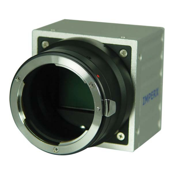
Page 33: Figure 1.8A - C-Mount Gige Cameras - Ipx-Vga-G / 1M48-G / 2M30-G / 2M30H-G
LYNX Hardware User’s Manual Figure 1.8a - C-mount GigE cameras – IPX-VGA-G / 1M48-G / 2M30-G / 2M30H-G Figure 1.8b - F-mount GigE cameras – IPX-4M15-G / 11M5-G / 16M3-G 33 of 209... -
Page 34: Figure 1.9 - Peltier Cooled Cl And Gige Cameras - Ipx-4M15T / 11M5T / 16M3T
LYNX Hardware User’s Manual Figure 1.9 – Peltier cooled CL and GigE cameras – IPX-4M15T / 11M5T / 16M3T Figures 1.10 to 1.15 show the dimensional drawings of IPX-VGA, IPX-1M48, IPX-2M30/H, IPX-4M15, IPX-11M5 and IPX-16M3 respectively. All dimensions are in millimeters. As of 10.01.06 11M5-L and all GigE models are shipped with black finned mid housing for better heat transfer. -
Page 35: Figure 1.10A - Ipx-Vga120-L And Ipx-Vga210-L Dimensional Drawings
LYNX Hardware User’s Manual IPX-VGA120-L / IPX-VGA210-L Figure 1.10a - IPX-VGA120-L and IPX-VGA210-L Dimensional Drawings. 35 of 209... -
Page 36: Figure 1.10B - Ipx-Vga210-G (Silver Body) Dimensional Drawings
LYNX Hardware User’s Manual IPX-VGA210-G Figure 1.10b - IPX-VGA210-G (Silver Body) Dimensional Drawings 36 of 209... - Page 37 LYNX Hardware User’s Manual IPX-VGA210-G Figure 1.10c - IPX-VGA210-G (Black Body) Dimensional Drawings 37 of 209...
-
Page 38: Figure 1.11A - Ipx-1M48-L Dimensional Drawings
LYNX Hardware User’s Manual IPX-1M48-L Figure 1.11a - IPX-1M48-L Dimensional Drawings 38 of 209... -
Page 39: Figure 1.11B - Ipx-1M48-G (Silver Body) Dimensional Drawings
LYNX Hardware User’s Manual IPX-1M48-G Figure 1.11b - IPX-1M48-G (Silver Body) Dimensional Drawings 39 of 209... - Page 40 LYNX Hardware User’s Manual IPX-1M48-G Figure 1.11c - IPX-1M48-G (Black Body) Dimensional Drawings 40 of 209...
-
Page 41: Figure 1.12A - Ipx-2M30-L And Ipx-2M30H-L Dimensional Drawings
LYNX Hardware User’s Manual IPX-2M30-L / IPX-2M30H-L Figure 1.12a - IPX-2M30-L and IPX-2M30H-L Dimensional Drawings 41 of 209... -
Page 42: Figure 1.12B - Ipx-2M30-G And Ipx-2M30H-G (Silver Body) Dimensional Drawings
LYNX Hardware User’s Manual IPX-2M30-G / IPX-2M30H-G Figure 1.12b - IPX-2M30-G and IPX-2M30H-G (Silver Body) Dimensional Drawings 42 of 209... -
Page 43: Figure 1.12C - Ipx-2M30-G And Ipx-2M30H-G (Black Body) Dimensional Drawings
LYNX Hardware User’s Manual IPX-2M30-G / IPX-2M30H-G Figure 1.12c - IPX-2M30-G and IPX-2M30H-G (Black Body) Dimensional Drawings 43 of 209... -
Page 44: Figure 1.13A - Ipx-4M15-L Dimensional Drawings
LYNX Hardware User’s Manual IPX-4M15-L Figure 1.13a - IPX-4M15-L Dimensional Drawings 44 of 209... -
Page 45: Figure 1.13B - Ipx-4M15-G (Silver Body) Dimensional Drawings
LYNX Hardware User’s Manual IPX-4M15-G Figure 1.13b - IPX-4M15-G (Silver Body) Dimensional Drawings 45 of 209... - Page 46 LYNX Hardware User’s Manual IPX-4M15-G Figure 1.13c - IPX-4M1 5-G (Black Body) Dimensional Drawings 46 of 209...
-
Page 47: Figure 1.14A - Ipx-11M5-L (Silver Body) Dimensional Drawings
LYNX Hardware User’s Manual IPX-11M5-L Figure 1.14a - IPX-11M5-L (Silver Body) Dimensional Drawings 47 of 209... -
Page 48: Figure 1.14B - Ipx-11M5-L (Black Body) Dimensional Drawings
LYNX Hardware User’s Manual IPX-11M5-L Figure 1.14b - IPX -11M5-L (Black B ody) Dimensional Drawings 48 of 209... -
Page 49: Figure 1.14C - Ipx-11M5-G (Silver Body) Dimensional Drawings
LYNX Hardware User’s Manual IPX-11M5-G Figure 1.14c - IPX-11M5-G (Silver Body) Dimensional Drawings 49 of 209... -
Page 50: Figure 1.14D - Ipx-11M5-G (Black Body) Dimensional Drawings
LYNX Hardware User’s Manual IPX-11M5-G ure 1.14d - IPX-11M5-G (Black Body) Dimensio nal Drawings 50 of 209... -
Page 51: Figure 1.15A - Ipx-16M3-L Dimensional Drawings
LYNX Hardware User’s Manual IPX-16M3-L Figure 1.15a - IPX-16M3-L Dimensional Drawings 51 of 209... -
Page 52: Figure 1.15B - Ipx-16M3-G Dimensional Drawings
LYNX Hardware User’s Manual IPX-16M3-G Figure 1.15b - IPX-16M3-G Dimensional Drawings 52 of 209... -
Page 53: Figure 1.16 - Ipx-4M15T/11M5T/16M3T Dimensional Drawings
LYNX Hardware User’s Manual IPX-4M15T, IPX-11M5T, IPX-16M3T Figure 1.16 – IPX-4M15T/11M5T/16M3T Dimensional Drawings 53 of 209... -
Page 54: Optical
F-mount lenses, which have a 46.5 mm back focal distance – Figure 1.17. An F-mount lens can be used with a C-mount camera via an F-mount to C-mount adapter, which can be purchased separately – refer to the Imperx web side for more information. The camera performance and signal to noise ratio depends... -
Page 55: Environmental
LYNX Hardware User’s Manual 1.5.3 Environmental The camera is designed to operate from -5 to 50 C in a dry environment. The relative humidity should not exceed 80% non-condensing. Always keep the camera as cool as possible. Always allow sufficient time for temperature... -
Page 56: Chapter 2 - Camera Features
LYNX Hardware User’s Manual LYNX Hardware User’s Manual Chapter 2 – Camera Features Camera Features This chapter discusses the camera’s features and their use. 56 of 209 56 of 209... -
Page 57: Resolution And Frame Rate
LYNX Hardware User’s Manual 2.1 RESOLUTION AND FRAME RATE 2.1.1 Single Output When operating in the single output m ode, all pixels are shifted out of the D register towards the left video amplifier – Video L (Figure 2.1). The... -
Page 58: Dual Output
LYNX Hardware User’s Manual 2.1.2 Dual Output When operating in a dual output mode, the image is split in two equal parts, each side consisting of half of the horizontal pixels and the full vertical lines. The first (left) half of the pixels are shifted out of the HCCD register towards the left video amplifier –... -
Page 59: Center Columns Output (Ipx-Vga210-L/G Only)
LYNX Hardware User’s Manual 2.1.3 Center Columns Output (IPX-VGA210-L/G only) The ‘center columns’ output mode is only available in the IPX-VGA210-L/G. In this mode the image field has only 228 horizontal pixels located in the center of the imager – Figure 2.3. When operating in a single output mode, all 228 pixels are shifted out of the HCCD register towards the left video amplifier –... -
Page 60: Figure 2.4 - Center Columns Output In Dual Mode Of Operation
LYNX Hardware User’s Manual Figure 2.4 - Center Columns Output in Dual Mode of Operation Figure 2.5 - Center Columns Output in Dual Tap Mode 60 of 209... -
Page 61: Timing Diagrams
LYNX Hardware User’s Manual 2.1.4 Timi ng Diagrams IPX-VGA120-L, IPX-VGA210-L/G In the single mode each line consists of 12 empty pixels (E1 – E12), followed by 24 masked pixels used for black reference (R1 – R24), followed by 4 buffer pixels (B1 – B4), followed by 640 active data pixels (D1 –... -
Page 62: Figure 2.7 - Dual Output Line Timing (Ipx-Vga210-L/G)
LYNX Hardware User’s Manual 4 buffer 320 active 12 empty 24 dark pixels data pixels pixels pixels 300 ns 600 ns 100 ns 8000 ns DATA 1 D639 - 0 - - 0 - DATA 2 D640 - 0 -... -
Page 63: Ipx-Vga210-L/G - Center Columns Operation
LYNX Hardware User’s Manual IPX-VGA210-L/G – Center Columns Operation In the center columns single mode, each line consists of 228 active data pixels (D1 – D228), followed by 18 dark (over-clocked) pixels (R1 – R18) – Figure 2.9. In the center columns dual mode, each line consists of 6 masked (over-clocked) pixels (R1 –... -
Page 64: Ipx-1M48-L/G
LYNX Hardware User’s Manual IPX-1M48-L/G In the single mode, each line consists of 8 empty pixels (E1 – E8), followed by 12 masked pixels used for black (dark) reference (R1 – R12), followed by 2 buffer pixels (B1, B2), followed by 1000 active pixels (D1 –... -
Page 65: Figure 2.13 - Single / Dual Output Frame Timing (Ipx-1M48-L/G)
LYNX Hardware User’s Manual 4 dark lines 2 buffer lines 2 buffer lines 1000 active lines TL HB DATA - 0 - - 0 - - 0 - - 0 - - 0 - - 0 - DL1000 - 0 -... -
Page 66: Ipx-2M30-L/G
LYNX Hardware User’s Manual IPX-2M30-L/G In the single mode, each line consists of 4 empty pixels (E1 – E4), followed by 16 masked pixels used for black (dark) reference (R1 – R16), followed by 4 buffer pixels (B1 – B4), followed by 1600 active data pixels (D1 –... -
Page 67: Figure 2.16 - Single / Dual Output Frame Timing (Ipx-2M30-L/G)
LYNX Hardware User’s Manual 2 dark lines 4 buffer lines 4 dark lines 4 buffer lines 1200 active lines TL HB DATA - 0 - - 0 - - 0 - - 0 - - 0 - - 0 -... -
Page 68: Ipx-2M30H-L/G
LYNX Hardware User’s Manual IPX-2M30H-L/G In the single mode, each line consists of 4 empty pixels (E1 – E4), followed by 28 masked pixels used for black (dark) reference (R1 – R28), followed by 4 buffer pixels (B1 – B4), followed by 1920 active data pixels (D1 –... -
Page 69: Figure 2.19 - Single / Dual Output Frame Timing (Ipx-2M30H-L/G)
LYNX Hardware User’s Manual 4 dark lines 1080 active lines 2 buffer lines 4 dark lines 2 buffer lines TL HB DATA - 0 - - 0 - - 0 - - 0 - - 0 - - 0 -... -
Page 70: Ipx-4M15-L/G
LYNX Hardware User’s Manual IPX-4M15-L/G single mo e, each line con ists of 1 empty pixels (E1 – E12 ollowe by 28 m sked p ls used for black (dark) reference (R1 – R28), followed by 4 buffer pixels (B1 – 4), fol... -
Page 71: Figure 2.22 - Single / Dual Output Frame Timing (Ipx-4M15-L/G)
LYNX Hardware User’s Manual 10 dark lines 8 buffer lines 6 buffer lines 2048 active lines TL HB DATA - 0 - - 0 - RL10 - 0 - - 0 - - 0 - - 0 - DL2048 - 0 -... -
Page 72: Ipx-11M5-L/G
LYNX Hardware User’s Manual IPX-11M5-L/G In the single m ode, each line consists of 4 empty pixels (E1 – E4), followed by 20 masked pixels used for black reference (R1 – R2 followed by 16 buffer pixels (B1 – B16), followed by 4000 active data pixels (D1 –... -
Page 73: Figure 2.25 - Single / Dual Output Frame Timing (Ipx-11M5-L/G)
LYNX Hardware User’s Manual 8 buffer lines 16 dark lines 2672 active lines 16 dark lines 8 buffer lines TL HB DATA - 0 - - 0 - - 0 - - 0 - - 0 - RL16 - 0 -... -
Page 74: Ipx-16M3-L/G
LYNX Hardware User’s Manual IPX-16M3-L/G In the single mo e, each line consists of 16 empty pixels (E1 – E16), followed by 28 masked pixels used for black reference (R1 – R28), followed by 16 buffer pixels (B1 – B16), followed by 4872 active data pixels (D1 –... -
Page 75: Figure 2.27 - Dual Output Line Timing (Ipx-16M3-L/G)
LYNX Hardware User’s Manual 16 buffer 2436 active 13 empty 28 dark pixels data pixels pixels pixels 464 ns 1000 ns 572 ns 87000 ns DATA 1 - 0 - R28 B1 - 0 - D4871 DATA 2 D4872 - 0 -... -
Page 76: Area Of Interest
2.2.1 Horizontal and Vertical Window Horizontal and vertical windowing (Area Of Interest) is supported in all LYNX cameras. Emphasizing a particular area of interest in horiz ntal direction is possible by using a horizontal win dow feature, where the beginning part of each line (pixel 1 to ‘Start Pixel’) and the end of each line (‘End Pixel’... -
Page 77: Calculating The Frame Rate Using Vertical Window
LYNX Hardware User’s Manual IPX- IPX- IPX- IPX- IPX- IPX- IPX- Feature VGA210-L 1M48-L 2M30-L 2M30H-L 4M15-L 11M5-L 16M3-L Start Pixel - Min. Start Pixel - Max. 1599 1919 2047 3999 4871 End Pixel - Min. End Pixel - Max. -
Page 78: Ipx-Vga120-L
LYNX Hardware User’s Manual IPX-VGA120-L FR [fps] = 1 / [(0.70 x 10 x (492 – WS)) + T + (WS x T (2.1a) is a constant = 35.35 x 10 sec., and T is the active line duration (T 18.38 x 10... -
Page 79: Ipx-Vga210-L/G
LYNX Hardware User’s Manual IPX-VGA210-L/G FR [fps] = 1 / [(0.70 x 10 x (492 – WS)) + T + (WS x T (2.1b) s a constant (T = 35.35 x 10 for single and d ual mode), and T... -
Page 80: Ipx-1M48-L/G
LYNX Hardware User’s Manual IPX-1M48-L/G FR [fps] = 1 / [(7.2 x 10 x (1010 – WS)) + T + (WS x T (2.1c) is a constant (T = 60.90 x 10 for single and dual mode), and T is the active line duration (T = 33.1 x 10... -
Page 81: Ipx-2M30-L/G
LYNX Hardware User’s Manual IPX-2M30-L/G FR [fps] = 1 / [(4.00 x 10 x (1214 – WS)) + T + (WS x T )] (2.1d) is a constant (T = 82 x 10 for single mode, and T = 62 x 10 for dual mode), and T is the active line duration (T = 45.18 x 10 for single... -
Page 82: Ipx-4M15-L/G
LYNX Hardware User’s Manual IPX-4M15-L/G FR [f ps] = 1 / [(4.00 x 10 x (2072 – WS)) + T + (WS x T 2.1e) is a constant (T = 122.1 x 10 for single mode, and T = 95.7 x 10... -
Page 83: Ipx-11M5-L/G
Note: The minimum vertical window size for t he IPX-11M5 is 400 lines. you require support for less than 400 lines then please contact Imperx. Figure 2.35 - Frame Rate vs. Vertical Window Size (IPX-11M5-L/G) 83 of 209... -
Page 84: Ipx-16M3-L/G
Note: The minimum vertical window size for the IPX-16M3 is 400 lines. If you require support for less than 400 lines then please contact Imperx. Figure 2.36 - Frame Rate vs. Vertical Window Size (IPX-16M3-L/G) 84 of 209... -
Page 85: Binning
LYNX Hardware User’s Manual 2.3 BINNIN Binni ng uses the CCD sensor to combine adjacent pixels in both directions to effec tively create larger pixels and less resolution. In 2:1 horizontal binning mode, two a djacent pixels in each line are summed together (in the horizontal direction), for ex ample, pixels 1+2, 3+4, 5+6, …... - Page 86 LYNX Hardware User’s Manual CAUTION NOTE Horizontal or vertical binning used alone changes the aspect ratio of the image in the vertical or horizontal direction. To correct this, use horizontal and vertical binning simultaneously. The frame-grabber vertical and horizontal resolution should be changed to reflect the actual number of active pixels and lines.
-
Page 87: Exposure Control
LYNX Hardware User’s Manual 2.4 EXPOSURE CONTROL 2.4.1 Electronic Shutter During normal camera operation, the exposure time is fixed and determined by the frame rate. The electronic shutter can be used to precisely control the image exposure time under bright light conditions. The electronic shutter does not affect the frame rate, it only reduces the amount of electrons collected. -
Page 88: Long Integration
LYNX Hardware User’s Manual the camera frame rate from 2 fps (0.5 s integration time) up to the nominal cam ra speed – refer to Table 2.1, with a precision of 1.0 fps. Optionally, the user can enter the desired frame rate in units of time instead of units of fps. -
Page 89: Figure 2.40 - Long Integration
LYNX Hardware User’s Manual be calculated using formula 4.2. This mode is displayed on the LED by slow pulsation with a 2 second interval – refer to Status LED section. Frame rate [fps] = 1 / long integration time [sec] (4.2) -
Page 90: External Trigger
The hardware trigger input in LYNX with camera link output is optically isolated from the rest of the camera hardware - Figure 2.41a. The input signals “+ TRIGGER IN” and “–... -
Page 91: Figure 2.41B - Hardware Trigger Electrical Connection - Gige Output
The hardware trigger input in LYNX with GigE output is directly connected to the camera hardware – Figure 2.41b. The trigger signal MUST be LVTTL (3.3V) or TTL (5.0 V). -
Page 92: Standard Triggering - Programmable Exposure
LYNX Hardware User’s Manual 2.5.2 Standard Triggering - Programmable Exposure When the standard triggering mode is enabled, the camera idles and waits for a trigger signal. Upon receiving the external trigger signal, the camera clears the horizontal and vertical registers, sends one 5 microseconds shutter pulse to clear the pixels and starts integration. -
Page 93: Fast Synchronized Triggering - Rapid Capture
LYNX Hardware User’s Manual TRIGGER EXPO SURE First Frame Exposure FVAL DATA DATA Out STROBE Only if the strobe is enabled Figure 2.42 - Standard Triggering Timing 2.5.3 Fast Synchronized Triggering – Rapid Capture Fast synchronized triggering (a.k.a. rapid capture) provides the ability to run the camera in a slave mode, allowing several cameras to be synchronized with an external master trigger signal. -
Page 94: Double Exposure Triggering
LYNX Hardware User’s Manual TRIGGER EXPOS Exposure N+2 Exposure N-1 Exposure N Exposure N+1 Exposure N+3 DATA N-2 DATA N-1 DATA N DATA N+1 DATA N+2 Only if the strobe is enabled Figure 2.43 - Fast Synchronized Triggering - Rapid Capture 2.5.4... -
Page 95: Figure 2.44 - Double Exposure Triggering
LYNX Hardware User’s Manual CAUTION NOTE It is recommended that the minimum time duration between the events is greater then the vertical transfer pulse duration: a. 5 microseconds for VGA, 1M48, 2M30, 2M30H and 4M15. b. 10 microseconds for 11M5 and 16M3. -
Page 96: Strobe Output
LYNX Hardware User’s Manual 2.6 STROBE OUTPUT 2.6.1 Strobe Positioning The strobe output is used to synchronize an external light source with the camera timing, and thus to maximize the camera efficiency in low light level conditions. The optimal strobe signal position is achieved by the positioning of a short pulse, STROBE, (duration 200 µs) with respect to the vertical... -
Page 97: Figure 2.46A - Strobe Output Electrical Connection (Internal) - Camera Link
LYNX Hardware User’s Manual CAUTION NOTE The maximum voltage difference between the strobe outputs is 8 volts! The maxim um output cur rent must not exceed 40mA! + STROBE OUT + 5.0V 2N3904 1.0K - STROBE OUT FROM CAMERA C A M E R A Figure 2.46a - Strobe Output Electrical... -
Page 98: Strobe Electrical Connectivity - Lynx With Gige Output
LYNX Hardware User’s Manual 2.6.3 Strobe Electrical Connectivity – LYNX with GigE Output The strobe output is directly connected to the cam era hardware and is 3.3 V LVTTL compatible signal. The maximum output c urrent MUST NOT exceed 8 mA. -
Page 99: Gain And Offset
LYNX Hardware User’s Manual 2.7 GAIN and OFF The camera has dual analog signal processors (or Analog Front End – AFE), one per channel. It features two independent 12 bit 40 MHz processors, each containing a differential input sample-and-hold amplifier (SHA), digitally controlled variable gain amplifier (VGA), black level clamp and a 12-bit ADC. -
Page 100: Data Output Format
LYNX Hardware User’s Manual 2.8 DATA OUTPUT FORMAT The internal camera processing of the CCD data is performed in 12 bits. The camera can output the data in 12, 10 or 8 bit format. During this standard bit reduction process, the least significant bits are truncated – Figure 2.49. -
Page 101: Transfer Function Correction - User Lut
LYNX Hardware User’s Manual 2.9 TRANSFER FUNCTION CORRECTION – USER LUT he user defined LUT (Lookup Table) feature allows the user to modify and transform the original video data into any arbitrary value – Figure 2.50. Any 12-bit value can be transformed into any other 12-bit value. The camera supports two separate lookup tables, each consisting of 2048 entries, with each entry being 12 bits wide. -
Page 102: User Defined Lut - Examples
LYNX Hardware User’s Manual Figure 2.51 - Gamma Corrected Video Signal 2.9.2 User D efined LUT - Examples The use r can define any 12-bit to 12-bit transformation as a user LUT and can upload it to the camera using the configuration utility software. If the camera resolution is set to 8 or 10 bit, the camera will truncate the corresponding LSB’s... -
Page 103: Figure 2.52 - Custom Lut
LYNX Hardware User’s Manual Modified TF Original TF Input signal Figure 2.52 - Custom LUT Example 2 – Knee correction In this example only 2 knee points have been introduced, the first one is at (400H) and the second at (A00H). The number of knee points is not limited. -
Page 104: Figure 2.54 - Contrast Correction
LYNX Hardware User’s Manual Example 3 – Contrast Correction Modified TF Original TF Input signal Figure 2.54 - Contrast Correction Example 4 – Negative Image Modified TF Original TF Input signal Figure 2.55 - Negative Image 104 of 209... - Page 105 LYNX Hardware User’s Manual Example 5 – Digital Shift The “Digital Shift” feature allows the user to change the group of bits sent to the camera output and therefore manipulate the camera brightness and contrast. The internal camera processing of the data is 12 bits. If the camera is set to output 10 bits of data then the two least significant bits are truncated.
- Page 106 LYNX Hardware User’s Manual Example C. Performing a non-standard 12 to 10 bit conversion: The original camera data is D0 (LSB) to D11 (MSB) Input Data - 12 bit D10 D11 Create a LUT, which truncates the 2 most significant bits (bits are shifted with two to the right).
-
Page 107: Dynamic Signal-To-Noise Correction
LYNX Hardware User’s Manual 2.10 YNAMIC SIGNAL-TO-NOISE CORRECTION As was described in the section 2.7 (Gain and Offset), the reference black level on each CCD output fluctuates around 0V – Figure 2.56. The AFE offset correction works on the entire image and if there are noise fluctuations on a line level, the AFE is not capable of correcting them. -
Page 108: Image Reversal
LYNX Hardware User’s Manual 2.11 IMAGE REVERSAL When operating in the image reversal mode, all pixels are shifted to the output in the reverse order. The resultant image appears left/right mirrored in the horizontal direction – Figure 2.57. This feature could be useful if the camera receives a mirrored image (i.e. -
Page 109: Negative Image
LYNX Hardware User’s Manual 2.12 NEGATIVE IMAGE When operating in the negative image mode, the value of each pixel is inverted. The resultant image appears negative – Figure 2.58. This feature could be useful if the camera receives a negative image (i.e. image from microfilms, prints or slides). -
Page 110: Camera Interface
LYNX Hardware User’s Manual 2.13 CAMERA INTERFACE 2.13.1 Status LED The camera has a green LED, located on the back panel, which indicates the camera status and mode of operation. • LED is steady ON – Normal operation. The user is expected to see a normal image coming out of the camera. -
Page 111: Integration Time Monitor
LYNX Hardware User’s Manual the LED on the back of the camera starts to blink rapidly. The alarm is for indication only and does not prevent the camera from continue to operate normally. Integration Time Monitor The camera has a built in integration time monitor. In any mode of operation ( i.e. -
Page 112: Test Mode
LYNX Hardware User’s Manual 2.14 TEST MODE The camera can output three test images (two fixed and one moving), which can be used to verify the camera’s general performance and connectivity to the fram grabber. This ensures that all the m... -
Page 113: Automatic Iris Control
LYNX Hardware User’s Manual 2.15 AUTOMATIC IRIS CONTROL The camera has an optional auto iris control feature. If enabled, the camer calculates th e average image brightness within the frame and compares it to a user specified threshold level – refer to the ‘sai’ command. If the calculated brigh tness level is less then the threshold, the camera sends a signal to open the lens iris. -
Page 114: Flat Field Correction
‘sfc on’ ( Set Flatfield Correction – On ) command. Each Imperx camera is shipped with the Flat Field Correction file that was creat for that camera during factory final testing. Users may wish, however, to crea... -
Page 115: Figure 2.61 - Original Image Showing 'Shading' Effect
LYNX Hardware User’s Manual Figure 2.61 – Original image showing ‘shading’ effect Figure 2 .62 – F lat Fie ld Corrected image 115 of 209... -
Page 116: Thermo-Electric Cooling ( Tec )
LYNX Hardware User’s Manual 2.18 THERMO-ELECTRIC COOLING ( TEC ) Activ e cooling of the CCD- imager throug h solid state thermoelectric cooler ( Peltier element ) is available on the IPX-4M15T, IPX-11M5T and IPX-16M3T cameras. The C CD imager is... -
Page 117: Chapter 3 - Camera Configuration
LYNX Hardware User’s Manual Chapt er 3 – Camera Configuration Camera C onfigu rati This chapter discusses how to con figure the camera’s operating parameters. 117 of 209... -
Page 118: Overview
LYNX Hardware User’s Manual 3.1 Overview The Lynx series of cameras are highly programmable and flexible. All of the camera’s features and opera ting parameters can be controlled by the user. The user communicates with the ca mera using simple ASCII commands via the C amera Link’s serial interface. -
Page 119: Configuration Memory
LYNX Hardware User’s Manual 3.2 Configuration Memory The camera has a built-in config uration memory divided into 4 segments: ‘work- space’, ‘factory-space’, ‘user-space #1’ and ‘user-space #2’. The ‘work-space’ segment contains the current camera settings while the camera is powered-up and operational. -
Page 120: Command Format
LYNX Hardware User’s Manual Command Format Command strings consist of a command token followed by up to two param eters. The forma t of the command string is: <comm and> <parm1> <parm2><cr> In response to the receipt of a command string, the camera will perform the intended op eration and return a response string. -
Page 121: Command Help
LYNX Hardware User’s Manual Command Help The came a will return a list of availab le commands when the user enters the ‘h’ command. For comma nd specific help, enter , and the cam era will display the ‘h <cmd>’... -
Page 122: Startup Procedure
LYNX Hardware User’s Manual Startup procedure Upon power on or receipt of an command, the cam era performs the following ‘rc’ steps: RISC pr ocessor runs and execute s code from internal read only memory. The boot loader cod ds the st ring: “Boot loader version x.y running…”... -
Page 123: Saving And Restoring Settings
LYNX Hardware User’s Manual Saving and Restoring Set tings Operation l settings for the camera may be stored for later retrieval in its non- volatile m emory. Three separate configuration spaces exist for storing these settings: ‘f actory’ space, ‘user #1’ space and ‘user #2’ space. The fac... -
Page 124: Load From User
LYNX Hardware User’s Manual 3.6.4 Load From User ( ‘lfu’ command instructs t he camera to load its workspace from one of ‘lfu’ the wo user spaces. All current workspace settings will be replaced with the conte nts of the selected user space. -
Page 125: Retrieving Manufacturing Data
LYNX Hardware User’s Manual Retrieving Manufacturin g Data The cam era contains non-volatile memory that stores manufacturing related informatio n. This information is programmed in the factory during the manufacturing process. 3.7.1 Get Manufacturing Data ( ‘gmd ’ command r... -
Page 126: Get Software Version
LYNX Hardware User’s Manual 3.7.5 Get Software Version ( ‘gsv’ command returns th e camera’s software version. ‘gsv’ Syntax: Resp onse: Camera responds with its software version, bootloader version and customer ID ( for custom software ). Exam ple: SW v1.0 BL v2.0 CUST 4... -
Page 127: Command Description
LYNX Hardware User’s Manual Command Descripti Ho izontal Window 3.8.1.1 Set Horizontal Window ( ‘shw’ and sets the horizontal area of intere st. The camera will ‘shw’ deliver to th amer a Link i nterface, per line, only th e range of pixels specified by this mand. -
Page 128: Vertical Window
LYNX Hardware User’s Manual 3.8.2 Vertical Window 3.8.2.1 Set Vertical Window ( ‘svw’ command sets the vertical area of interest. The camera will ‘svw’ deliver to the Camera Link interface, per frame, only the range of lines specified by this command. Using this command increases the effective frame rate of the camera and also reduces the automatic exposure time ( when shutter is disabled ). -
Page 129: Shutter Time
LYNX Hardware User’s Manual 3.8.3 Shutter Time 3.8.3.1 Set Shutter Time ( ‘sst’ command sets the shutter timing. ‘sst’ Syntax: sst <off|i> Parameter: Disables the shutter mode. The shutter time in units of uSeconds. Range: min=50 max= the lesser of 500,000 or 1/frame rate Example: Sets the shutter time to 80 uSeconds. -
Page 130: Long Integration
LYNX Hardware User’s Manual 3.8.4 Long Integration 3.8.4.1 Set Long Integration ( ‘sli’ command sets the long integration timing. ‘sli’ Syntax: sli <off|i> Parameter: Disables the long integration mode. The long integration time in units of mSeconds. Range: min=10 max=10,000... -
Page 131: Strobe Position
LYNX Hardware User’s Manual 3.8.5 Strobe Position 3.8.5.1 Set Strobe Position ( ‘ssp’ command sets the position of the strobe pulse output. The ‘ssp’ strobe pulse position is set relative to the end of the frame. Syntax: ssp <off|i> Parameter: Disables the strobe. -
Page 132: Analog Gain
LYNX Hardware User’s Manual 3.8.6 Analog Gain 3.8.6.1 Set Analog Gain ( ‘sag’ command sets the analog gain of the camera. ‘sag’ Syntax: sag <0|1|2> <i> <j> Parameter #1: Sets b oth taps to the same gain or to different gains. -
Page 133: Analog Offset
LYNX Hardware User’s Manual 3.8.7 Analog Offset 3.8.7.1 Set Analog Offset ( ‘sao’ command sets the analog offset of the camera. ‘sao’ Syntax: sao <0|1|2> <i> <j> Parameter #1: Sets both taps to the same offset or to different offsets. -
Page 134: Dual Tap Mode
LYNX Hardware User’s Manual 3.8.8 Dual Tap mode 3.8.8.1 Set Dual Mode ( ‘sdm’ command sets the camera to operate in either single or dual ‘sdm’ tap mode. Syntax: sdm <on|off> Parameter: Selects dual tap operation. Selects single tap opertio... -
Page 135: Bit Depth
LYNX Hardware User’s Manual Bit Depth 3.8.9.1 Set Bit Depth ( ‘sbd’ comm and sets th e bit depth of the camera. ‘sbd ’ Syntax: sbd <8|10|12> Parameter: Selects 8 bit operation. Selects 10 bit operation. Selects 12 bit operation. -
Page 136: Lookup Table Operation
LYNX Hardware User’s Manual 3.8.10 Lookup Table Operation 3.8.10.1 Set Lookup Table ( ‘slt’ command instructs the camera to perform a table lookup ‘slt’ procedure on all pixels. The table maps a 12 bit input pixel value to a 12 bit output pixel value. -
Page 137: Noise Correction Processing
LYNX Hardware User’s Manual Noise Correction processing 3.8.11.1 S et Noise Correction ( ‘snc’ command instructs the camera to perform noise correction ‘snc’ processing on all incoming pixels. During this process, the camera averages the leadin g dark pixels in each line and determines what the average noise level is. -
Page 138: Horizontal Mode
LYNX Hardware User’s Manual 3.8.12 Horizontal mode 3.8.12.1 Set Horizontal Mode ( ‘shm’ command configures the camera to operate in the normal, ‘shm’ window, binning or center modes. The normal mode turns off window, binning and center modes. In the windowing mode of operation, the horizontal area of interest is defined by the command. -
Page 139: Vertical Mode
LYNX Hardware User’s Manual 3.8.13 Vertical Mode 3.8.13.1 Set Vertical Mode ( ‘svm’ command configures the camera to operate in either the ‘svm’ normal, windowing or binning modes. The no rmal mode turns off both windowi ng and binnin g. In the windowing mode of operation, the... -
Page 140: Test Pattern Generation
LYNX Hardware User’s Manual Test Pattern generation 3.8.14.1 S et Test Mode ( ‘gtm’ command instructs the camera to enter a test mode and ‘stm’ deliver a test pattern to the Camera Link interface. This command is useful during frame grabber configuration and when troubleshooting the camera to frame grabber interface. -
Page 141: Image Reversal Mode
LYNX Hardware User’s Manual 3.8.15 Image Reversal mode 3.8.15.1 Set Image Reversal ( ‘sir’ command instructs the camera to perform image reversal. ‘sir’ During image reversal the camera will deliver pixels, to the Camera Link interface, in the reverse order from which they were received by the CCD sensor resulting in a mirror image being displayed. -
Page 142: Trigger Operation
LYNX Hardware User’s Manual Trigger operation 3.8.16.1 S et Trigger ( ‘str’ command instructs the camera to exit the free running mode ‘str’ of operation and to enter into a trigger mode. In the trigger mode, the camera will idle and wait for a trigger event to occur. When the trigger... -
Page 143: Set Trigger Duration
LYNX Hardware User’s Manual 3.8.16.3 Set Trigger Duration ( ‘std’ command sets the number of frames to be transmitted after a ‘std’ trigger event occurs. Syntax: std <i> Parameter: The number of frames to be transmitted after the trigger. A value between 250... -
Page 144: Set Pre-Exposure ( )
LYNX Hardware User’s Manual 3.8.16.7 S et Pre-Exposure ( ‘spe’ command sets the exposure time for the first frame after a ‘spe’ trigger event when the trigger is in the ‘standard’ mode.. The first frame after a trigger will be exposed for the length of time specified. -
Page 145: Set Double Exposure
LYNX Hardware User’s Manual 3.8.16.9 Set Double Exposure ( ‘sde’ command sets the expo sure time for the first frame after a ‘sde’ trigger event when the trig ger is in the ‘double’ mode. The first frame after a trigger will be exposed for the length of time specified. -
Page 146: Negative Image Mode
LYNX Hardware User’s Manual 3.8.17 Negative Image mode 3.8.17.1 Set Negative Image ( ‘sni’ command instructs the camera to perform image inversion. ‘sni’ During image inversion, the camera will perform a one’s compliment on all pixels before delivering them to the Camera Link interface resulting in a negative image being displayed. -
Page 147: Temperature Monitoring
LYNX Hardware User’s Manual 3.8.18 Temperature Monitoring 3.8.18.1 Get Current Temperature ( ‘gct’ command returns the current temperature of the cam era. The ‘g ct’ temper ature is in increments of .25 degrees C. Syntax: Response: Camera temperature in degrees centigrade... -
Page 148: Set Temperature Threshold
LYNX Hardware User’s Manual 3.8.18.4 Set Temperature Threshold ( ‘stt’ command defines the ‘on’ and ‘off’ temperature thresholds ‘stt’ that will trigger the camera to send temperature warnings. The thresholds are in increments of 1 degrees C. If the camera’s ambient temperature exceeds the ‘on’... -
Page 149: Programmable Frame Rate
LYNX Hardware User’s Manual 3.8.19 Programmable Frame Rate 3.8.19.1 Set Frame Rate ( ‘sfr’ command instructs the cam era to throttle the camera frame ‘sfr’ rate from the current free-running rate to a slower rate. This command is useful when the user wishes to reduce the amount of bandwidth required on the Camera Link interface. -
Page 150: Set Frame Time
LYNX Hardware User’s Manual 3.8.19.3 Set Frame Time ( ‘sft’ command instructs the camera to throttle the camera frame ‘sft’ rate from the current free-running rate to a slower rate. This command is useful when the user wishes to reduce the amount of bandwidth required on the Camera Link inte rface. -
Page 151: Current Speed And Exposure
LYNX Hardware User’s Manual 3.8.20 Current Speed and Exposure 3.8.20.1 Get Camera Speed ( ‘gcs’ command returns the measured operating speed ( frame rate ) ‘gcs’ of the came ra. The current operating speed is determined by a num ber of settings ( see note below ). - Page 152 LYNX Hardware User’s Manual 3.8.20.2 Get Camera Exposure ( ‘gce’ command returns the measured exposure ( integration ) tim e of ‘gce’ camera. The current exposure time is determined by a number of settings ( see note below ). The camera is capable of measuring the current exposure time in all modes of operation.
-
Page 153: Defective Pixel Correction
LYNX Hardware User’s Manual 3.8.21 Defective Pixel Correction 3.8.21.1 Set Defect Correction ( ‘sdc’ command instructs the camera to perform defective pixel ‘sdc’ correction processing on the entire frame. During this process, as the camera process each pixel it looks up the pixel’s location in the on-board Defective Pixel Map ( stored in non-volatile memory ). -
Page 154: Flat Field Correction
LYNX Hardware User’s Manual 3.8.22 Flat Field Correction 3.8.22.1 Set Flatfield Correction ( ‘sfc’ command instructs the camera to perform the Flat Field ‘sfc’ correction procedure. During this procedure, the camera reads a set of Flat Field coefficients from on-board non-volatile memory. It uses these coefficients to compensate for any variations in the pixel responsivity. -
Page 155: Chapter 4 - Lynx Configurator For Cameralink
LYNX Hardware User’s Manual Chapter 4 – LYNX Configurator for CameraLink LYNX Configurator for CameraLink This chapter provides a quick reference to using the Lynx Configurator camera configuration utility for the Camera Link series of Lynx cameras. 155 of 209... -
Page 156: Overview
LYNX Hardware User’s Manual Overview The LYNX Configurator is provided with each Camera Link camera. This tool communicates with the camera, via the frame grabber’s Camera Link serial interface. It allows the user to configure the camera’s operating mode and to create, load and save camera configuration profiles. -
Page 157: Setup
(the green LED on the back i lit) and that the Camera Link cable is connected. Make sure that the frame grabber of choice is properly installed. Click on the LYNX Configurator icon. Often times multiple fra grabb ers an d cam ras may be installed into a computer at the same time. - Page 158 LYNX Hardware User’s Manual After having selected the desired camera, the main LYNX Configurator dialog will appear. The graphical user interface is ve ry intuitive and self -explanatory. The configuration utility includes an interactive help file, which will guide you through the GUI controls and camera settin The user can also reveal a small ‘Terminal Dialog’...
-
Page 159: Graphical User Interface
LYNX Hardware User’s Manual Grap hical User Interface The LYNX Configurator is a graphical us er interface (G UI) containing six main panels (tabs): • AOI (Area Of Interest) • Trigger • Vide o Am • Exposure • Strobe • Auto Iris... - Page 160 LYNX Hardware User’s Manual Center: When enabled, the center (fast) mode is activated. This feature is only available on the IPX-VGA210L/G. VERTICAL AOI Normal: When enabled, the imager has full vertical resolution. Window: When enabled, the user can set the vertical resolution using the sliders or by entering the desired start and end values.
-
Page 161: Trigger Tab
LYNX Hardware User’s Manual 4.3.2 Trigger Tab The Trigger tab, shown in Figure 4.4, is used to set the different triggering modes. Figure 4.4 - Triggering Tab TRIGGER – selects the trigger source. Off: When enabled, the camera is free running. -
Page 162: Video Amp Tab
LYNX Hardware User’s Manual CC EXPOSURE CONTROL - CC Exposure control is active only if the camera is set to “CC trigger”. Camera: When enabled, the user can also set the exposure time for the first frame via the “First Frame Exp. – Standard” slider. -
Page 163: Auto Iris Tab
LYNX Hardware User’s Manual 4.3 .4 Auto Iris Tab Auto Iris Tab controls the auto iris feature – Figure 4.6 Figure 4.6 - Auto Iris Tab Iris Threshold: When enabled, the user can set the iris threshold (brightness of the image) via the slider or by entering the desired value. -
Page 164: Strobe Tab
LYNX Hardware User’s Manual Long When enabled, the user can set the camera to Long Integration: Integration mode. The integration time can be programmed via the slider or by entering the desired value. This feature is used to extend the camera integration. -
Page 165: Common Controls
LYNX Hardware User’s Manual 4.3.7 Common Controls All panels in the LYNX Configurator share the same general control options and menus for “File”, “Boot”, “Test Mode” and “Help” – Figure 4.9. Figure 4.9 – LYNX Configurator main dialog. 165 of 209... - Page 166 FILE MENU Load from File: Loads the camera registers from a saved configurati file. Load from Loads the LYNX Configurator GUI with the current kspace: status of the c amera registers. Load from Loads the camera registers and LYNX Configurator...
-
Page 167: Figure 4.10 - Lynx Terminal Dialog Window
Show/Hide This command will display/hide the LYNX Terminal: Terminal Dialog Window – Figure 4.10 Figure 4.10 - LYNX Terminal Dialog Window. Dump Defect This command will display a listing of the contents Pixels: of the Defective Pixel Correction table in non-volatile memory. - Page 168 LYNX Hardware User’s Manual COMMON CONTROLS and DISPLAYS Taps - Selects the camera output format. Single: Sets the camera to a single output mode. Dual: Sets the camera to a dual output m epth - Selects the output bit depth.
-
Page 169: Chapter 5 - Lynx Interface Application For Gige
LYNX Hardware User’s Manual Chap ter 5 – LYNX Interface Application fo GigE LYN I terface Application for GigE This chapter discusses the LYNX GigE interface software. 169 of 209... -
Page 170: Overview
Prior to connecting the camera ma ke sure that the LYNX GigE application and high perf ormance dr iver a re p roperly nstalled. The high performance driver is optimized... -
Page 171: Setup
"Start" in Acquisition Control. Yo u should ee an image. To stop the image acquisition – click on the “Stop” button. o acce the ca era features, click on the “LYNX Configurator” tab and select the settings you wish to modify. 171 of 209... -
Page 172: Graphical User Interface
LYNX Hardware User’s Manual Graphical User Interface For a detailed description of the LYNX GigE Interface Application’s graphical user interface ( GUI ) plea se refer to the “LYNX GigE Software User’s Manual”. For software inst allation struction , refer to Appendix E of this manual. -
Page 173: Chapter 6 - Warranty And Support
LYNX Hardware User’s Manual Chap er 6 – W arranty an d Support Lyn W ranty and Support This chapter discusses the camera’s warranty and support. 173 of 209... -
Page 174: Ordering Information
LYNX Hardware User’s Manual ORDERING INFORMATION NOTE: For any other custom camera configurations, please contact Imperx, Inc. 174 of 209... -
Page 175: Technical Support
LYNX Hardware User’s Manual TECHNICAL SUPP Each camera is fully tested before shipping. If for some reason the camera is not oper ational aft er po wer u p pl ease check t he following: C ec th power supply an d all I/O cables. -
Page 176: Warranty
Redistribution of this manual in whole or in part, by any means, is prohibited without obtaining prior permission from Imperx. Imperx reserves the right to make changes to its products or to discontinue any product or service without notice, and advises its customers to... -
Page 177: Appendix A - Camera Configuration Reference
LYNX Hardware User’s Manual LYNX Hardware User’s Manual Appendix A – Camera Configuration Reference Camera Configuration Reference This appendix provides a quick reference to the cam era configuration comm res ons 177 of 209 177 of 209... -
Page 178: General Commands
LYNX Hardware User’s Manual A.1 General Commands Command Syntax Parm String Description returned Help Displa a list o all commands Help specific Displays the description and syntax for the specified command. Get Work various Returns a l ting of all camera parameters. -
Page 179: Retrieving Manufacturing Data
LYNX Hardware User’s Manual A.2 Retrieving Manufacturing Data Command Syntax String Description returned Get Manufacturing Data various Returns all MFG Data. Get Model Number various Returns era model number. Get Assembly Number various Returns the camera assembly number. Get Firmware Version various Returns FPGA firmware version number. -
Page 180: Restricted Commands
LYNX Hardware User’s Manual A.4 Restricted Commands ( Note: these are only available in supervisor mode ) Command Syntax Parm#1 Parm#2 String Description Returned Save to Factory Camera writes workspace registers to EEPROM factory space. Note1 Programs the MFG data area of the camera. -
Page 181: Configuring Workspace Settings
LYNX Hardware User’s Manual A.5 Configuring Workspace Settings Operating Modes Command Syntax Parm#1 Parm#2 Description Set Bit Depth 8|10|12 Sets the camera bit depth Set Dual Mode on|off Enables dual tap operation: off = single tap mode on = dual tap mode... - Page 182 LYNX Hardware User’s Manual Area of Interest Command Syntax Parm#1 Parm#2 Description Set Horizontal Window Sets the horizontal window. The first parameter, x1, is the starting pixel number and the second parameter, x2, is the ending pixel number. Set Vertical Window Sets the vertical window.
-
Page 183: Trigger Control
LYNX Hardware User’s Manual Trigger Control Command Syntax Parm#1 Parm#2 Description Set Trigger off|cc|et s|f|d Sets the trigger mode: off = disabled cc = CC1 et = external s = standard f = fast d = double Set Trigger Duration... -
Page 184: Table A.5 - Workspace 'Set' Commands
LYNX Hardware User’s Manual Strobe Control Command Syntax Parm#1 Parm#2 Description Set Strobe Position off|i Sets the strobe position: off = disabled i = strobe position in uSeconds Auto Iris Control Command Syntax Parm#1 Parm#2 Description Set Auto Iris off|i... -
Page 185: Retrieving Workspace Settings
LYNX Hardware User’s Manual A.6 Retrieving workspace settings Operating Modes Command Syntax Parm#1 String Description returned Get Bit Depth 8|10|12 Returns the current bit depth. Get Dual Mode on|off Returns the current dual mode setting: off = single tap mode... - Page 186 LYNX Hardware User’s Manual Area of Interest Command Syntax Parm#1 String Description returned Get Horizontal W indow x1 x2 Returns the current h orizontal window settings where ‘x1’ is the starting pixel number and ‘x2’ is the ending pixel number.
- Page 187 LYNX Hardware User’s Manual Trigger Control Command Syntax Parm#1 String Description returned Get Trigger off|cc|et Returns the current trigger mode setting: off = disabled cc = CC1 et = external s|f|d s = standard f = fast d = double...
-
Page 188: Table A.6 - Workspace 'Get' Commands
LYNX Hardware User’s Manual Strobe Control Command Syntax Parm#1 String Description returned Get Strobe Position off|i Returns the current strobe position: off = disabled i = strobe position in uSeconds Auto Iris Control Command Syntax Parm#1 String Description returned Get Auto Iris... -
Page 189: Appendix B - Lynx Terminal
LYNX Hardware User’s Manual Appendix B – Lynx Terminal Lynx Terminal This appendix provides a quick reference to using the Lynx camera download and console utility. This utility is used by both the Camera Link and GigE cameras. 189 of 209... -
Page 190: Overview
Whereas the Lynx Configurator utility provides a graphical user interface to the camera, the Lynx Terminal utility provides a command line interface. The download utility allows the user to download newly released software, firmware or a user defined lookup table into t he cameras non-volatile memory. -
Page 191: Figure B.2 - Plug-Ins Panel
LYNX Hardware User’s Manual Plug-ins Panel: Clicking on the ‘Plug-ins’ tab reveals the following panel. Figure B.2 – Plug-ins panel Select all of the plug-ins by checking the boxes listed. The next step is to click on the ‘Properties’ tab. -
Page 192: Figure B.3 - Camera Link Transport Properties Panel
LYNX Hardware User’s Manual Properties Panel: Click on the ‘Properties’ tab to reveals the following panel. You may select either the ‘Camera Link’ , ‘GigE’ or ‘Serial Transport’ options. Select the ‘Ca mera Link’ option if the comp uter is connected to the camera using a Camera Link compliant serial interface. -
Page 193: Figure B.4 - Gige Transport Properties Panel
LYNX Hardware User’s Manual Figure B.4 – GigE Transport Properties panel If you have selected ‘GigE’, then the program will display the Imperx clserilg.dll serial interface dri ver used to connect to GigE cameras. The next step is to click on the ‘Transport’... -
Page 194: Figure B.5 - Serial Transport Properties Panel
LYNX Hardware User’s Manual Figure B.5 – Serial Transport Properties panel If you h ected ‘Serial Transport’, then you must choose the COM port in the erial pull-down menu and configure its operating parameters ( i.e. ‘Bits per second’, ‘Data Bits’, etc. ). The next step is to click on the ‘Transport’ tab. -
Page 195: Figure B.5 - Transport Dialog
Select the desired interface, Camera Link, GigE or Serial Transport, and click the ‘OK’ button. All of the above settings will be saved in the registry and will automatically be recalled the next time you invoke the Lynx Terminal program. You are now ready to begin communicating with the camera. -
Page 196: Download Utility
LYNX Hardware User’s Manual B.3 Download Utility Selecting the ‘Loader View’ reveals the following screen. Figure B.6 – Loader View dialog The user can select to download either new Camera Software, Camera BootLoader, Camera Firmware, a Lookup Table, a Defect Correction table or a Flat Field Correction table by selecting the appropriate button. -
Page 197: Terminal Utility
( refer to Appendix A ) enter into this console will be sent to the c amera using the transport method chosen during the Lynx Terminal setup. Camera responses sent by the c era will be displayed in this console as well. 197 of 209... -
Page 198: Appendix C - Creating Look Up Tables
LYNX Hardware User’s Manual Appendix C – Creating Look Up Tables reating Look Up Tables This appendix provides a reference on how to create a lookup table using h an ASCII editor and an Excel spreadsheet. 198 of 209... -
Page 199: Overview
LYNX Hardware User’s Manual C.1 Overview The Lookup Table f ile can be created using any standard ASCII text e ditor or by using Micro soft Ex el. Additionally, any spreadsheet or mathematical program capable of generatin g a comma delimited file can be used C.2 Using an AS... -
Page 200: Using Microsoft Excel
LYNX Hardware User’s Manual C.3 Using Micros oft Excel The .LUT file can be created in Excel as follows: 1 - create the spreadsheet as shown below ( note that 4096 rows are required in the table ). - add the necessary equations into the output cells to generate the transfer function required. -
Page 201: Appendix D - Lynx Cameralink Software Installation
LYNX Hardware User’s Manual Appendix D – LYNX CameraLink Software Installation LYNX CameraLink Software Installation This appendix explains how to install the LYNX CameraLink software. 201 of 209... -
Page 202: Software Suite
LYNX Hardware User’s Manual D.1 Software Suite The LYNX software suite consists of the following files: Windows XP and 2000 application files: ( located in c:\Program_Files\ImperX\LYNX\ ) LYNX_Configurator.exe - LYNX Configurator application LYNX_Terminal.exe - LYNX Terminal main executable CameraLinkPlugin.dll - Camera Link plugin module LoaderViewPlugin.dll... -
Page 203: Software Installation From Cd
LYNX Hardware User’s Manual D.2 Software Installation from CD Use the following steps to install the LYNX software supplied on a CD: If a version of LYNX was previously installed on this machine, then you must first remove it: Left mouse click on “Start”... - Page 204 LYNX Hardware User’s Manual Download the LYNX_Installer_x_x_x_x.exe file (x represents the revision) from the Imperx web site to a new folder on your PC (we will use the folder C:\new_LYNX as an example). Left mouse click on “Start”, “Run” then enter or browse to “C:\new_LYNX\ LYNX_Installer_x_x_x_x.exe”.
-
Page 205: Appendix E - Lynx Gige Software Installation
LYNX Hardware User’s Manual Appendix E – LYNX GigE Software Installation LYNX GigE Software Installation This appendix explains how to install the LYNX GigE software. 205 of 209... -
Page 206: Software Suite
C:\Program_Files\Imperx\LYNX GigE\Samples E.2 Software and Driver Installation from CD Use the following steps to install the LYNX GigE software supplied on a CD: If a version of LYNX GigE was previously installed on this machine, then you must first remove it: Left mouse click on “Start”... - Page 207 LYNX Hardware User’s Manual Insert the LYNX GigE CD into the appropriate drive; the setup.exe file will run automatically. Note: If it does not start automatically, left mouse click on to “Start”, “Run”, enter or browse to“(CD drive): setup.exe” and click “OK”.
-
Page 208: Software Upgrade From Web Site
1. of the ‘Software Installation from CD’ section. Download the LYNX_GigE_x_x_x.exe file (x represents the revision) from the Imperx web site to a new folder on your PC (we will use the folder C:\new_LYNX.GigE as an example). Left mouse click on “Start”, “Run” then enter or browse to “C:\new_LYNX GigE\ LYNX_GigE_x_x_x.exe”. -
Page 209: Driver, Software And Sdk Documentation
For a detailed description of the high performance driver and driver installation, please refer to “LYNX GigE Driver Manual” For a detailed description of the LYNX GigE Application software, please refer to the “LYNX GigE Software User’s Manual”. For a detailed description of the function calls supported by the SDK, refer to the “LYNX GigE C++ SDK Reference Guide”...
Need help?
Do you have a question about the LYNX and is the answer not in the manual?
Questions and answers