
Subscribe to Our Youtube Channel
Related Manuals for Metos 92/04 VTC


Summary of Contents for Metos 92/04 VTC
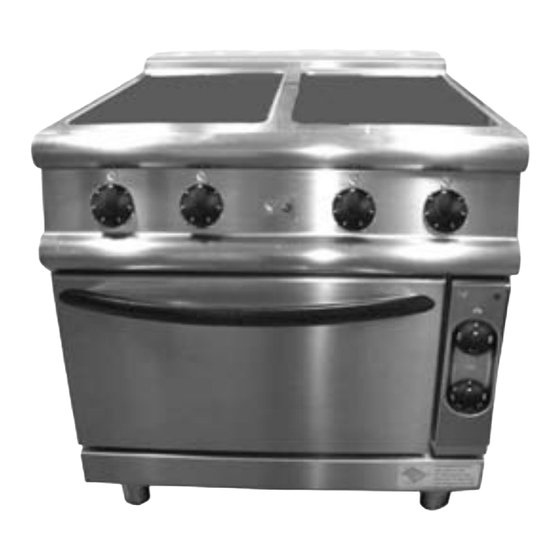
- Page 1 ELECTRIC RANGES CERAMIC GLASS 900 Series TYPE: 92/04 VTC, 94/04 VTC, 94/04 VTCE, 92/04 TVTC, 94/04 TVTC User Manual S/N: Valid from:23. 10. 2007 Rev.: 1.1...
- Page 3 Dear Customer, Congratulations on deciding to choose a Metos appliance for your kitchen activities. You made an excellent choice. We will do our best to make you a satisfied Metos customer like thousands of customers we have around the world.
- Page 4 24.10.2007 Rev. 1.1...
-
Page 5: Table Of Contents
24.10.2007 Rev. 1. General information ..................1 1.1 Symbols used in the manual ..................1 1.2 Symbols used on the appliance ..................2 1.3 Checking correspondence between the appliance and the manual ........ 2 2. Safety ......................3 2.1 Using the appliance safely ..................... 3 2.2 Safety instructions in the event of a fault .............. - Page 6 24.10.2007 Rev. 5. Installation ....................17 5.1 General information ..................... 17 5.1.1 Regulatory installation conditions ............... 17 5.2 Exhausting fumes ......................17 5.3 Possible environmental interference ................17 5.4 Storage ......................... 18 5.5 Unpacking the appliance ..................... 18 5.6 Disposal of packaging materials ................18 5.7 Positioning ........................
-
Page 7: General Information
24.10.2007 Rev. 1.1 General information 1. General information Read the instructions in this manual carefully, as they contain important information on how to install, use and service the appliance safely, properly, and effectively. Keep this manual in a safe place so that it can be used as reference by other operators of the appliance. -
Page 8: Symbols Used On The Appliance
24.10.2007 Rev. 1.1 General information 1.2 Symbols used on the appliance This symbol on a part warns the user that there are electrical terminals behind it. There- fore, the concerned part should only be removed by qualified personnel. 1.3 Checking correspondence between the appliance and the manual The serial number for the appliance is given on the rating plate. -
Page 9: Safety
24.10.2007 Rev. 1.1 Safety 2. Safety 2.1 Using the appliance safely Being an appliance designed for professional use only, it should be operated exclusively by qualified personnel. Never leave the appliance unattended while in use! Do not move the appliance while hot! Personnel who wear pacemakers or metal prostheses must take care when using the appli- ance. - Page 10 24.10.2007 Rev. 1.1 Safety...
-
Page 11: Functional Description
24.10.2007 Rev. 1.1 Functional description 3. Functional description 3.1 Appliance application The electric induction cooker is designed for cooking products in suitable pots or pans placed on the ceramic glass top. The electric cooker was designed to cook products in suitable pots or pans placed on the ceramic glass top. -
Page 12: Cooking Tops
24.10.2007 Rev. 1.1 Functional description 3.3 Cooking tops 3.3.1 Fig. 1a Cooking zone, 180 mm diameter (1.3 kW) Cooking zone, 270 mm diameter (2.1 kW) • Each cooking zone is marked by silkscreened concentric circles, indicating the various heating levels; •... -
Page 13: Cooking Top Operating Principle
24.10.2007 Rev. 1.1 Functional description 3.5 Cooking top operating principle 3.5.1 Ceramic glass The heating elements installed under the ceramic glass top heat the surface to the required temperature, and a max. of 550 °C can be reached in just a few minutes. The pot absorbs the heat by means of contact and radiance. - Page 14 24.10.2007 Rev. 1.1 Functional description...
-
Page 15: Operating Instructions
24.10.2007 Rev. 1.1 Operating instructions 4. Operating instructions 4.1 Before use If the glass breaks, the appliance cannot be used due to the risk of electric shocks. 4.1.1 Preparazione al funzionamento Remove all packaging materials and adhesive films very carefully. Remove the protective film from the panels, ensuring no traces of glue are left on the steel surface;... -
Page 16: Using The Appliance
24.10.2007 Rev. 1.1 Operating instructions 4.2 Using the appliance 4.2.1 Switching on the cooking top Vetroceramica Turning the knob (pos. 1 in Fig. 2) to the desired position switches on the power indicator light (pos. 2 in Fig. 2) . This means that the appliance is on and the selected cooking zone is beginning to heat up. -
Page 17: Cooking
24.10.2007 Rev. 1.1 Operating instructions 4.2.2 Cooking • Select the cooking temperature by means of the energy regulator. • When cooking food, energy saving depends on the quality of the pots and, in par- ticular, their bottoms. • The pot diameter must match that of the cooking zone. Use pots suitable for elec- tric hot-plates. -
Page 18: Lighting The Electrical Oven
24.10.2007 Rev. 1.1 Operating instructions 4.2.4 Lighting the electrical oven Choose the heating direction on the knob indicated as (pos. 3 in Fig. 6). Set the cooking chamber temperature by turning the oven operating thermostat knob in clockwise direc- tion (from pos. 4b to pos. 4c in Fig. 6), lthe heating elements start to operate and the line pilot lamp (pos. -
Page 19: After Having Used The Appliance
24.10.2007 Rev. 1.1 Operating instructions 4.3 After having used the appliance 4.3.1 Cleaning Before cleaning, switch the appliance off and disconnect its power supply. General information The main causes for stainless steel wear or corrosion are: • using abrasive or acid detergents especially chlorine-based products, such as hy- drochloric acid or sodium hypochlorite (bleach). -
Page 20: Idle Period
24.10.2007 Rev. 1.1 Operating instructions Rust If you need to remove rust stains, contact manufacturers of industrial detergents to find a suitable product. Industrial descaling products can also be used to that end. After remov- ing stains and rinsing off the appliance with clean water, an alkaline detergent may be re- quired to neutralize any acid compounds left on the surface. -
Page 21: Cleaning Air Filter
24.10.2007 Rev. 1.1 Operating instructions 4.3.4 Cleaning air filter The following cleaning operations have to be done on a weekly basis: • Pull downward the filter fixing frame ( pos. 2 of Fig. 6a); Fig. 6a Filter Filter fixing frame Filter fixing screws •... - Page 22 24.10.2007 Rev. 1.1 Operating instructions...
-
Page 23: Installation
24.10.2007 Rev. 1.1 Installation 5. Installation 5.1 General information The manufacturer cannot be held liable for any injuries to persons or damage to property resulting from installation errors or from inappropriate use of the appliance and is not re- sponsible for any faults caused by defective installation. In such cases, the warranty shall be null and void. -
Page 24: Storage
24.10.2007 Rev. 1.1 Installation 5.4 Storage If the appliance is stored in a warehouse where room temperature is below 0° (32°F), it should be warmed up to at least +10° (50°F) before switching it on. 5.5 Unpacking the appliance Remove all packaging materials before installing the appliance. Some parts are wrapped in adhesive film, which have to be thoroughly removed. -
Page 25: Electrical Connections
24.10.2007 Rev. 1.1 Installation 5.8 Electrical connections 5.8.1 General information The appliance must always be connected to an earthing (grounding) system while in op- eration. The appliance is pre-set to be connected to the electrical control board. Before connecting the appliance to the power supply network, check: •... -
Page 26: Connecting The Cable For Y-Type Electrical Connection To The Appliance Terminal Block (Ceramic Glass Top And Sides)
24.10.2007 Rev. 1.1 Installation 5.8.3 Connecting the cable for Y-type electrical connection to the appliance terminal block (ceramic glass top and sides). Only the manufacturer's service centre or similarly trained individual may replace the power cable. To access the power terminal block, proceed as follows: •... -
Page 27: Connecting The Cable For Y-Type Electrical Connection To The Appliance Terminal Block [Model With Electric Oven]
24.10.2007 Rev. 1.1 Installation 5.8.4 Connecting the cable for Y-type electrical connection to the appliance terminal block [model with electric oven]. Only the manufacturer's service centre or similarly trained individual may replace the power cable. To access the power terminal block, proceed as follows: •... - Page 28 24.10.2007 Rev. 1.1 Installation Fig. 9 Terminal block Cable clamp Side panel fixing screws Side panel The terminal block is mounted on the lower compartment as shown in Fig.9. The power cable must be secured with the cable clamp fitted to the appliance (pos.2 in Fig.
-
Page 29: Equipotential Terminal
24.10.2007 Rev. 1.1 Installation 5.8.5 Equipotential terminal The appliance must be connected to an equipotential system. A connecting terminal has been provided on the lower right of the appliance for this purpose. Fig. 9a Equipotential terminal Right front foot... -
Page 30: Training Of Personnel
24.10.2007 Rev. 1.1 Installation 5.9 Training of personnel Train personnel in use of the appliance, making reference to and giving them the instruc- tion manual. Personnel who wear pacemakers or metal prostheses must take care when using the appli- ance. When the appliance is operating, keep the part with the prosthesis or pacemaker away from the work surface. -
Page 31: Troubleshooting
24.10.2007 Rev. 1.1 Troubleshooting 6. Troubleshooting If the appliance fails to work, first of all check for blown fuses (overload protection) in the fuse box. Have the overload protection device checked by a qualified technician. The operator is not to do maintenance work on any parts of this appliance. Maintenance has to be carried out by an authorized technician. - Page 32 24.10.2007 Rev. 1.1 Troubleshooting ADVICE PROBLEM POSSIBLE CAUSES FOR THE AUTHOR- FOR THE USER ISED INSTALLER Place the selector so that heat is generated by both Improper selector position or the bottom and the top of position not suitable to the the oven according to the type of cooking type of cooking to be per-...
-
Page 33: Technical Specifications
24.10.2007 Rev. 1.1 Technical specifications 8. Technical specifications Connection diagrams ......40 Installation and connection drawings. 46 Technical specifications table ....51... - Page 34 6SC00698: Wiring diagram 92/04VTCV-TVTCV 3/N/PE 400V ~ 50/60 Hz...
-
Page 35: Specifications
24.10.2007 Rev. 1.1 Technical specifications 6LE00789: legend of the wiring diagram 6SC00698 92/04VTCV-TVTCV - 3/N/PE~400V 50-60 Hz Letter code Codes Descriptions Specifications 6A035200 B5-7 Control thermostat 110°C - 1F 6A035210 Control thermostat 150°C - 1F 6A038506 Power indicator light 400V - 150°C 6A038506 Safety indicator light 400V - 150°C... - Page 36 6SC00697: Wiring diagram 94/04VTCV-TVTCV 3/N/PE 400V ~ 50/60 Hz...
- Page 37 24.10.2007 Rev. 1.1 Technical specifications 6LE00788: legend of the wiring diagram 6SC00697 94/04VTCV-TVTCV - 3/N/PE~400V 50-60 Hz Letter code Codes Descriptions Specifications 6A035200 B1-3-5-7 Control thermostat 110°C - 1F 6A035210 B4-6 Control thermostat 150°C - 1F 6A038506 Power indicator light 400V - 150°C 6A038506 Safety indicator light...
- Page 38 6SC00696: Wiring diagram 94/04VTCEV 3/N/PE 400V ~ 50/60 Hz...
- Page 39 24.10.2007 Rev. 1.1 Technical specifications 6LE00787: legend of the wiring diagram 6SC00696 94/04VTCEV - 3/N/PE~400V 50-60 Hz Letter code Codes Descriptions Specifications 826630123 Control thermostat 50-300°C - 3F 826630130 Safety thermostat 360°C - 3F 6A035200 B1-3-5-7-9 Control thermostat 110°C - 1F 6A035210 B4-6-8 Control thermostat...
- Page 40 24.10.2007 Rev. 1.1 Technical specifications Installation drawing 92/04VTC DESCRIPTION Fitting electric connection cable Distance between feet Cooking zone diameter Terminal block Plate...
- Page 41 24.10.2007 Rev. 1.1 Technical specifications Installation drawing 94/04VTC DESCRIPTION Fitting electric connection cable Distance between feet Cooking zone diameter Terminal block Plate...
- Page 42 24.10.2007 Rev. 1.1 Technical specifications Installation drawing 94/04VTCE DESCRIPTION Fitting electric connection cable Distance between feet Cooking zone diameter Terminal block Plate...
- Page 43 24.10.2007 Rev. 1.1 Technical specifications Installation drawing 92/04TVTC DESCRIPTION Fitting electric connection cable Distance between feet Cooking zone diameter Terminal block Plate...
- Page 44 24.10.2007 Rev. 1.1 Technical specifications Installation drawing 94/04TVTC DESCRIPTION Fitting electric connection cable Distance between feet Cooking zone diameter Terminal block Plate...
-
Page 45: Technical Specifications
4 x 10 mm² Wire cross section 5 x 10 mm² Wire cross section 4 x 16 mm² Supply voltage 3/N/PE ~400V 50Hz Supply voltage 3/PE ~230V 50Hz 92=92/04 VTC, 94=94/04 VTC, 94E=94/04 VTCE, 92T=92/04 TVTC, 94T=94/04 TVTC A=3/N/PE∼400/230V 50Hz, H=3/PE∼230V 50Hz...
Need help?
Do you have a question about the 92/04 VTC and is the answer not in the manual?
Questions and answers