
Subscribe to Our Youtube Channel
Related Manuals for Metos 72/02CG


Summary of Contents for Metos 72/02CG
- Page 1 GAS RANGES 700 - Restaurant Series TYPE: 72/02CG, 72/02TGC, 74/02CG, 74/02TGC, 76/02CG, 76/02TGC, 74/02CGG, 74/ 02CGE, 76/02CGG, 76/02CGGE, 76/02CGE, 76/02CGEE, 76/02CGFL Installation and Operation Manual S/N: Rev.: 1.0...
- Page 3 Dear Customer, Congratulations on deciding to choose a Metos appliance for your kitchen activities. You made an excellent choice. We will do our best to make you a satisfied Metos customer like thousands of customers we have around the world.
- Page 4 30.7.2003 Rev. 1.0...
-
Page 5: Table Of Contents
30.7.2003 Rev. 1. General information ..................1 1.1 Symbols used in the manual ..................1 1.2 Symbols used on the appliance ..................1 1.3 Checking correspondence between the appliance and the manual ........ 2 2. Safety ......................3 2.1 Using the appliance safely ..................... 3 2.2 Safety instructions in case of malfunction .............. - Page 6 30.7.2003 Rev. 5. Installation ....................17 5.1 General information ..................... 17 5.1.1 Regulatory installation conditions ............... 17 5.2 Exhausting fumes ......................17 5.3 Possible environmental interference ................18 5.4 Preparing for installation ..................... 18 5.5 Storage ......................... 18 5.6 Transporting the appliance ..................18 5.7 Unpacking the appliance .....................
-
Page 7: General Information
2.9.2003 Rev. 1.0 General information 1. General information Read the instructions in this manual carefully, as they contain important information on how to install, use and service the appliance safely, properly, and effectively. Keep this manual in a safe place so that it can be used as reference by other operators of the appliance. -
Page 8: Checking Correspondence Between The Appliance And The Manual
2.9.2003 Rev. 1.0 General information 1.3 Checking correspondence between the appliance and the manual The rating plate of the appliance shows its serial number. If the manuals are missing, you may order new ones from the manufacturer or your local representative. When ordering new manuals it is essential to quote the serial number shown on the rating plate. -
Page 9: Safety
2.9.2003 Rev. 1.0 Safety 2. Safety 2.1 Using the appliance safely Being an appliance designed only for professional use, it should be operated by qualified personnel exclusively. Never leave the appliance unattended while it is on. Do not move the appliance while hot. 2.2 Safety instructions in case of malfunction If the appliance will remain idle for some time or in the event of a failure, abnormal op- eration, etc., turn off the shutoff valve upstream of the appliance and disconnect it from... - Page 10 2.9.2003 Rev. 1.0 Safety...
-
Page 11: Functional Description
2.9.2003 Rev. 1.0 Functional description 3. Functional description 3.1 Application of the appliance The appliance is designed for use in the gastronomy and confectionery industries only. 3.1.1 Prohibited use The manufacturer cannot be held liable for any faults caused by defective installation or inappropriate use of the appliance. -
Page 12: Cooking Surfaces
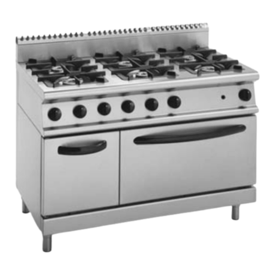
2.9.2003 Rev. 1.0 Functional description 3.2.2 Cooking surfaces Fig. 1 Burner rated 3.5 kW (open burners) Burner rated 5.6 kW (open burners) Burner rated 7.9 kW (oven) • Unit with 2, 4 or 6 stabilised-flame gas burners made of nickel-plated cast iron and controlled by pilot flames;... -
Page 13: Electric Ovens
2.9.2003 Rev. 1.0 Functional description 3.2.4 Electric ovens • Stainless steel GN 2/1 static oven with temperature adjustable from 50°C to 300°C (122°F to 572°F); • two sheathed heating units (top and bottom) separately adjustable through a selec- tor switch and controlled by a single thermostat; •... - Page 14 2.9.2003 Rev. 1.0 Functional description...
-
Page 15: Operating Instructions
2.9.2003 Rev. 1.0 Operating instructions 4. Operating instructions 4.1 Before using the appliance 4.1.1 Preparing the appliance for use Before cooking food for the first time, we recommend cleaning the appliance thoroughly, and especially the oven cooking chamber. Remove all packaging materials and adhesive films from the appliance very carefully. -
Page 16: Using The Appliance
2.9.2003 Rev. 1.0 Operating instructions 4.2 Using the appliance 4.2.1 Operating controls By way of example, below are represented two of the most comprehensive appliances in this family. Refer to the "Installation and connection drawings" at the end of this manual to see a precise graphic representation of your specific appliance. -
Page 17: Turning The Open Burners On And Off
2.9.2003 Rev. 1.0 Operating instructions 4.2.2 Turning the open burners on and off • To light the pilot flame, press the knob and turn it anti-clockwise to the position shown as item 14 in Fig. 3; • hold down the knob and at the same time place a flame next to the pilot burner; •... -
Page 18: Turning On The Gas Oven
2.9.2003 Rev. 1.0 Operating instructions 4.2.3 Turning on the gas oven • To light the gas oven pilot flame, press and turn the knob anti-clockwise to the po- sition shown as item 20 in Fig. 4; • hold down the knob and at the same time push the ignition button (see item 8 in Fig. -
Page 19: Turning On The Electric Oven
2.9.2003 Rev. 1.0 Operating instructions 300°C (572°F) 4.2.4 Turning on the electric oven Select the required heating direction using the knob shown as item 23 in Fig. 5. Set the cooking chamber temperature by turning the operating thermostat knob clockwise (item 24). -
Page 20: Turning On The Hot Cupboard
2.9.2003 Rev. 1.0 Operating instructions 4.2.5 Turning on the hot cupboard Select the desired temperature using the hot cupboard knob (item 7 in Fig. 5). The heating element will start operating and the operation indicator light (item 27 in Fig. 5) will light up. -
Page 21: After-Use Care
2.9.2003 Rev. 1.0 Operating instructions 4.3 After-use care 4.3.1 Cleaning Before cleaning, turn off the appliance, shut off gas supply upstream of it and disconnect power supply using the safety switch located outside the appliance. General information The main causes for stainless steel wear or corrosion are: •... -
Page 22: Idle Period
2.9.2003 Rev. 1.0 Operating instructions 4.3.2 Idle period If the appliance will remain idle for a certain period of time, clean it and wipe it dry first, and then apply a film of a suitable product (such as vaseline oil spray or similar products) to protect it. -
Page 23: Installation
2.9.2003 Rev. 1.0 Installation 5. Installation 5.1 General information The manufacturer cannot be held liable for any damage to property or injury to persons deriving from installation errors or from inappropriate use of the appliance and is not re- sponsible for any faults caused by defective installation. In such cases, the warranty shall be null and void. -
Page 24: Possible Environmental Interference
2.9.2003 Rev. 1.0 Installation 5.3 Possible environmental interference If the appliance is installed with its sides next to flammable walls (made of wood or sim- ilar materials) or to heat-sensitive walls (made of plasterboard or similar materials), suit- able protective measures should be taken to keep such walls undamaged. Therefore, apply a coating to insulate the walls from radiative heat or keep a minimum clearance of 100 mm (4") from the side and back panels of the appliance. -
Page 25: Positioning The Appliance
2.9.2003 Rev. 1.0 Installation 5.9 Positioning the appliance Level the appliance using a level. Height can be adjusted with the help of the adjustable feet. 5.10 Electrical connections (versions with electric oven and/or hot cupboard) 5.10.1 General information The appliance should be operated only when properly connected to an effective earthing (grounding) system. -
Page 26: Connecting A Type "Y" Power Cord To The Appliance's Terminal Block
2.9.2003 Rev. 1.0 Installation 5.10.2 Connecting a type "Y" power cord to the appliance’s terminal block The appliance is supplied complete with power cord. The power cord can only be replaced by the manufacturer, by the manufacturer’s service or by a technician having similar qual- ifications. - Page 27 2.9.2003 Rev. 1.0 Installation The power cord should be locked in place with the cable gland (item 31 in Fig. 7) so as to avoid the risk of tearing it. The length of the ground (earth) cable should be such as to allow it to suffer any possible mechanical stress after the live leads.
-
Page 28: Gas Supply Connection
2.9.2003 Rev. 1.0 Installation 5.11 Gas supply connection This appliance is designed to burn natural and liquid gas. To find out the category to which this appliance belongs in the country where it is installed, please refer to the table below. - Page 29 2.9.2003 Rev. 1.0 Installation The appliance should be connected to the gas supply by means of metal pipes --either rigid or flexible-- having an adequate diameter (see "Technical specifications table" at the end of this manual). When joining pipe fittings, never use oakum or Teflon as their residues could get to the valve and jeopardise its operation.
-
Page 30: Checking Gas Supply Pressure After Installation
2.9.2003 Rev. 1.0 Installation 5.12 Checking gas supply pressure after installation Gas supply pressure can be measured with a liquid-filled pressure gauge (for example, a U-shaped pressure gauge, minimum scale division 0.1 mbar) or a digital gauge. Proceed as follows: •... -
Page 31: Gas Technical Specifications
2.9.2003 Rev. 1.0 Installation 5.13 Gas technical specifications The appliance should be started up at its rated output with the nozzles shown in "Table 2: burner specifications" below. All the necessary nozzles are provided in a small bag to- gether with the appliance. The nozzles of the main burners are marked in hundredths of mm, while those of pilot flames have a reference number. - Page 32 2.9.2003 Rev. 1.0 Installation Table 2: burner specifications Oven G30/31 50 mbar Rated pressure (mbar) Reduced pressure (mbar), minimum Pilot flame 16·2 Nozzles (1/100 mm) Max. Min. Primary air distance (mm) * Apply the air register plate (see chapter "Replacing oven burner nozzles" in section "Ad- justment instructions").
-
Page 33: Checking Operation
2.9.2003 Rev. 1.0 Installation 5.14 Checking operation Start up the appliance by following the instructions given in chapter "Using the ap- pliance"; check for gas leaks; check for flame stability throughout the whole control range by going from high to low. 5.15 Staff training Inform all personnel assigned to operate the appliance on how to use it by referring to this user’s manual and hand them out the manual. - Page 34 2.9.2003 Rev. 1.0 Installation...
-
Page 35: Adjustment Instructions
2.9.2003 Rev. 1.0 Adjustment instructions 6. Adjustment instructions To convert (for example) from natural gas to liquid gas, you need to change the nozzles of main and pilot burners. The appropriate nozzles are shown in "Table 2: burner speci- fications". -
Page 36: Replacing Open Burner Nozzles
2.9.2003 Rev. 1.0 Adjustment instructions 6.1 Replacing open burner nozzles • Remove the grate, the flame spreader (item 40 in Fig. 10), the burner (item 41) and the drip pan; • unscrew the screw (item 44) that fixes the primary air sleeve (item 45) and remove the sleeve;... - Page 37 2.9.2003 Rev. 1.0 Adjustment instructions • adjust primary air distance (H in Fig. 11) according to the values shown in "Table 2: burner specifications". Fig. 11 Air sleeve...
-
Page 38: Replacing The Nozzle Of Open Burner Pilot Flames
2.9.2003 Rev. 1.0 Adjustment instructions 6.2 Replacing the nozzle of open burner pilot flames • Unscrew the sealing screw (item 61 in Fig. 12) using an 11-mm spanner, and re- move it; • unscrew the nozzle (item 59) with a flat-blade screwdriver and remove it; •... -
Page 39: Replacing Oven Burner Nozzles
2.9.2003 Rev. 1.0 Adjustment instructions 6.3 Replacing oven burner nozzles • Remove the lower front panel (item 28 in Fig. 13) by unscrewing the several screws shown as item 29; Fig. 13 Lower front panel Fixing screws • open the oven door and take out the bottom plates; •... - Page 40 2.9.2003 Rev. 1.0 Adjustment instructions Fig. 14 Screw Washer Nozzle holder Nozzle Burner • adjust primary air distance (H in Fig. 15) according to the values shown in "Table 2: burner specifications"; Fig. 15 Primary air sleeve Fixing screw Fixed air register for G25 natural gases Air register fixing holes...
-
Page 41: Replacing The Nozzle Of The Oven Pilot Flame
2.9.2003 Rev. 1.0 Adjustment instructions • if the appliance will be using type G25 natural gas --and only in this case--, remove the air sleeve and fit the air register plate (item 72 in Fig. 15); • replace the primary air sleeve and adjust it according to the values shown in "Table 2: burner specifications". -
Page 42: Adjusting Minimum Output
2.9.2003 Rev. 1.0 Adjustment instructions 6.5 Adjusting minimum output If the appliance will be using liquid gases, remove the knobs, insert a screwdriver through the hole and completely screw down the screw shown as item 86 in Fig. 17. Fig. 17 Screw to adjust minimum output Gas inlet pipe fitting Thermocouple pipe fitting... -
Page 43: Functional Check
2.9.2003 Rev. 1.0 Adjustment instructions • connect a liquid-filled pressure gauge (for example, a U-shaped pressure gauge, minimum scale division 0.1 mbar) or a digital gauge; • start up the appliance by following the instructions in the user’s manual; Gas pressure at minimum burner output should match the pressure values shown in "Table 2: burner specifications"... - Page 44 2.9.2003 Rev. 1.0 Adjustment instructions...
-
Page 45: Troubleshooting
2.9.2003 Rev. 1.0 Troubleshooting 7. Troubleshooting Users are not allowed to perform any maintenance operations on any parts of this appli- ance. Maintenance should be carried out by an authorized technician. TROUBLE POSSIBLE CAUSES WHAT TO DO FOR THE USER FOR THE INSTALLER OPEN BURNERS Pilot burner won’t... - Page 46 2.9.2003 Rev. 1.0 Troubleshooting TROUBLE POSSIBLE CAUSES WHAT TO DO FOR THE USER FOR THE INSTALLER GAS OVEN Pilot flame won’t light: piezoelectric ignition device replace it; faulty; the spark plug is not secure- check the connection; ly fixed, or the wire connec- tion is wrong;...
- Page 47 2.9.2003 Rev. 1.0 Troubleshooting TROUBLE POSSIBLE CAUSES WHAT TO DO FOR THE USER FOR THE INSTALLER ELECTRIC OVEN No heating: no power; check that the appliance is be- ing powered; A temperature is set but safety thermostat reset the thermostat the oven won’t turn on: tripped;...
- Page 48 2.9.2003 Rev. 1.0 Troubleshooting...
- Page 49 2.9.2003 Rev. 1.0 Technical specifications 9. Technical specifications Connection diagrams ........... 70 Installation and connection drawings......74 Technical specifications table........87 CE conformity declaration .......... 89...
- Page 51 SC00414: wiring diagram 74/02CGE, 76/02CGE - 3/N/PE ~400V 50-60 Hz...
- Page 52 6SC00473: wiring diagram 74/02CGE, 76/02CGE, 74/02CTGE - 3/PE ~230V 50-60 Hz...
- Page 53 SC00415: wiring diagram 76/02CGGE - 1/N/PE ~230V 50-60Hz...
- Page 54 SC00413: wiring diagram 76/02CGEE - 3/N/PE ~400V 50-60Hz...
-
Page 55: Technical Specifications
2.9.2003 Rev. 1.0 Technical specifications LE00385: key to wiring diagrams SC00414, 6SC00473 74/02CGE, 76/02CGE -.3/N/PE ~400V 50-60Hz, 3/PE ~230V 50-60Hz Letter code Art. no. Descriptions Specifications A044601 Control thermostat 50 - 275°C - 3F A046150 Safety thermostat 350°C - 3F A038506 Line pilot lamp 400V - 150°C... - Page 56 2.9.2003 Rev. 1.0 Technical specifications Installation and connection drawing 72/02CG...
- Page 57 2.9.2003 Rev. 1.0 Technical specifications Installation and connection drawing 72/02TCG...
- Page 58 2.9.2003 Rev. 1.0 Technical specifications Installation and connection drawing 74/02CG...
- Page 59 2.9.2003 Rev. 1.0 Technical specifications Installation and connection drawing 74/02TCG...
- Page 60 2.9.2003 Rev. 1.0 Technical specifications Installation and connection drawing 74/02CGG...
- Page 61 2.9.2003 Rev. 1.0 Technical specifications Installation and connection drawing 74/02CGE...
- Page 62 2.9.2003 Rev. 1.0 Technical specifications Installation and connection drawing 76/02CG...
- Page 63 2.9.2003 Rev. 1.0 Technical specifications Installation and connection drawing 76/02TCG...
- Page 64 2.9.2003 Rev. 1.0 Technical specifications Installation and connection drawing 76/02CGG...
- Page 65 2.9.2003 Rev. 1.0 Technical specifications Installation and connection drawing 76/02CGGE...
- Page 66 2.9.2003 Rev. 1.0 Technical specifications Installation and connection drawing 76/02CGE...
- Page 67 2.9.2003 Rev. 1.0 Technical specifications Installation and connection drawing 76/02CGEE...
- Page 68 2.9.2003 Rev. 1.0 Technical specifications Installation and connection drawing 76/02CGFL Gas supply connection Connection cable entry Distance between feet Distance between burners Rating plate Hot cupboard connection cable entry Terminal block...
- Page 69 2.9.2003 Rev. 1.0 Technical specifications Item Model Type Voltage Specification External dimensions WxDxH, freestanding unit CG 400x700x860/900 mm External dimensions WxDxH, freestanding unit 74, 74G, 74E, 74ST, 800x700x860/900 mm 74STG, 74STE External dimensions WxDxH, freestanding unit 76, 76G, 76GE, 76E, 1200x700x860/900 mm 76EE, 76FL, 76ST, 76STG, 76STGE...
- Page 70 2.9.2003 Rev. 1.0 Technical specifications Item Model Type Voltage Specification Rated output 76GE, 76STGE 0.42 kW Max. current 74E, 76E 8.1 A Max. current 74E, 76E 14.5 A Max. current 76GE 1.8 A Max. current 76EE 9.9 A Max. current 76EE 15.8 A Cable cross section...
- Page 71 Gas-Allgasherde serie 700 New Wir erklären, dass dieses Gerät: Cocina a gas gama 700 New Se declara que el siguiente aparato: Mod.: 72/02CG, 74/02CG, 76/02CG, 74/02CGG, 74/02CGE, 76/02CGG, 76/02CGGE, 76/02CGE, 76/02CGEE, 76/02CGFL, 72/02TCG, 74/02TCG, 76/02TCG è conforme alla direttiva 90/396 CEE...
Need help?
Do you have a question about the 72/02CG and is the answer not in the manual?
Questions and answers