Metos FUTURA RP4 Installation And Operation Manual
Hide thumbs
Also See for FUTURA RP4:
- Installation and operation manual (26 pages) ,
- Installation and operation manual (32 pages)

Related Manuals for Metos FUTURA RP4


Summary of Contents for Metos FUTURA RP4
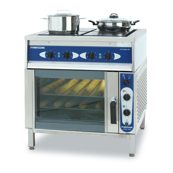
- Page 1 RANGE FUTURA RP4, RP6 Accessories CHEF 200 CHEF 220 CHEF 240 Installation and Operation Manual S/N: 095523/03 Rev.: 4.0...
- Page 3 7.5.2009 Rev. 4.0 Dear Customer, Congratulations on deciding to choose our appliance for your kitchen activities. You made an excellent choice. We will do our best to make you a satisfied customer like thou- sands of customers we have around the world. Please read this manual carefully.
- Page 4 7.5.2009 Rev. 4.0...
-
Page 5: Table Of Contents
7.5.2009 Rev. 1. General ......................1 1.1 Symbols used in the manual ..................1 1.2 Symbols used on the appliance ..................1 1.3 Checking the relationship of the appliance and the manual .......... 1 2. Safety ......................2 2.1 Safe use of the appliance ....................2 2.2 Disposal of the appliance .................... - Page 6 7.5.2009 Rev.
-
Page 7: General
7.5.2009 Rev. 4.0 General 1. General Carefully read the instructions in this manual as they contain important information re- garding proper, efficient and safe installation, use and maintenance of the appliance. Keep this manual in a safe place for eventual use by other operators of the appliance. The installation of this appliance must be carried out in accordance with the manufactur- er’s instructions and following local regulations. -
Page 8: Safety
7.5.2009 Rev. 4.0 Safety 2. Safety 2.1 Safe use of the appliance Because the range is a heated appliance that has hot surfaces during normal use, the fol- lowing warnings and instructions must be followed in order to avoid burns. During long-time operation even the frame surrounding the cooking plates gets hot. -
Page 9: Functional Description
7.5.2009 Rev. 4.0 Functional description 3. Functional description 3.1 Intended use of the appliance The Futura range is intended for preparing different kinds of foodstuffs using cookware. 3.1.1 Prohibited use Use of the appliance for other purposes than stated above is prohibited. Covering the gaps between the range cooking plates and the upper frame with folio is pro- hibited. -
Page 10: Operation Instructions
7.5.2009 Rev. 4.0 Operation instructions 4. Operation instructions 4.1 Before use The cooking plates of the range are protected with a thin layer of oil for the duration of storage and transportation. When heating up the range for the first time the oil may create some smoke and unpleasant smell. -
Page 11: After Use
7.5.2009 Rev. 4.0 Operation instructions Operating panel Spillage tray Pilot light, cooking plate on Power regulator, front plate Power regulator, rear plate Each cooking plate is equipped with a 7-position power regulator which allows power regulation in several steps. A green pilot light for every cooking plate indicates that the plate is on. -
Page 12: Other Service Measures
7.5.2009 Rev. 4.0 Operation instructions When cleaning the cooking plates, observe that they are hot a long time after they have been switched off. When the cooking plates are swinged up for cleaning, it is advisable to support the plate in the upper position with one hand thus preventing the possibility that they unexpectedly return to their working position. -
Page 13: Installation
7.5.2009 Rev. 4.0 Installation 5. Installation 5.1 General The installation of this appliance must be carried out in accordance with the manufactur- er’s instructions and following local regulations. This installation manual must be used together with the installation drawing of the appliance. The connection of the appliance to the electrical and water supply must be carried out by qualified persons only. -
Page 14: Test-Run
7.5.2009 Rev. 4.0 Installation In order to make eventual future service easier and increase safety, a mains switch must be installed near the appliance. This switch must disconnect the appliance completely from the electrical supply network. The cable gland for the supply cable is located on the rear wall of the oven (right lower corner). -
Page 15: Troubleshooting
7.5.2009 Rev. 4.0 Troubleshooting 6. Troubleshooting If the appliance does not function, check the following: • Has the appliance been used according to the instructions? • Are all possibly removable parts refitted? • Is the mains switch on the appliance or nearby - often on the wall - in the ON po- sition? •... - Page 16 7.5.2009 Rev. 4.0 Troubleshooting...
-
Page 17: Spare Parts
7.5.2009 Rev. 4.0 Spare parts 7. Spare parts... - Page 18 7.5.2009 Rev. 4.0 Spare parts...
-
Page 19: Voltage Codes
7.5.2009 Rev. 4.0 Spare parts 7.1 Voltage codes Voltage Voltage code 3/N/PE∼400/230V 50Hz ∼250V 16A 50Hz 3/N/PE∼380/220V 50Hz 3/PE∼200V 50-60Hz 2/PE 220−240V 50Hz 3/N/PE∼415/240V 50Hz 3/PE∼230V 50Hz 3/PE∼220V 60Hz 3/PE∼380 50Hz 3/PE∼400V 50Hz 3/PE∼415V 50Hz 3/PE∼440V 60Hz 3/PE∼460V 60Hz 3/PE∼480V 60Hz 1/N/PE~220-240V 50Hz 2/PE~220-230V 60Hz 3/N/PE∼400/230V 50Hz... - Page 20 7.5.2009 Rev. 4.0 Spare parts...
- Page 21 7.5.2009 Rev. 4.0 Spare parts Code Model Type Voltage Description Module: 3752924 A,H,I Cooking plate 3752971 A,H,I Cable conduit 3752940 A,H,I Eyebolt M12x90 3752937 A,H,I Rear panel 3753140 A,H,I Rear panel 3752933 A,H,I Side panel 3493234 A,H,I Knob, black 3442159 A,H,I Pilot light, green 3753180...
- Page 22 7.5.2009 Rev. 4.0 Spare parts...
- Page 23 7.5.2009 Rev. 4.0 Spare parts Code Model Type Voltage Description Module: 3753052 J,L,M Cooking plate 3752971 J,L,M Cable conduit 3752940 J,L,M Eyebolt M12x90 3752937 J,L,M Rear panel 3753140 J,L,M Rear panel 3752933 J,L,M Side panel 3493234 J,L,M Knob, black 3442159 J,L,M Pilot light, green 3753180...
- Page 24 7.5.2009 Rev. 4.0 Spare parts...
-
Page 25: Technical Specifications
7.5.2009 Rev. 4.0 Technical specifications 8. Technical specifications Main and control circuit T02119 B3 Main and control circuit T02120 B3 Main and control circuit T02121 B3 Main and control circuit T02122 B3 Main and control circuit T02123 B3 Main and control circuit T02124 B3 Main and control circuit T02130 B3 Main and control circuit T02131 B3 Main and control circuit T02132 B3... - Page 26 Main and control circuit T02119 B3...
- Page 27 Main and control circuit T02120 B3...
- Page 28 Main and control circuit T02121 B3...
- Page 29 Main and control circuit T02122 B3...
- Page 30 Main and control circuit T02123 B3...
- Page 31 Main and control circuit T02124 B3...
- Page 32 Main and control circuit T02130 B3...
- Page 33 Main and control circuit T02131 B3...
- Page 34 Main and control circuit T02132 B3...
- Page 35 Main and control circuit T02146 A3...
- Page 36 Installation drawing T02194 B3...
- Page 37 Installation drawing T02195 B3...
- Page 38 Installation drawing T02196 B3...
- Page 39 Installation drawing T02197 B3...
- Page 40 Installation drawing T02198 B3...
- Page 41 Installation drawing T02199 B3...
- Page 42 7.5.2009 Rev. 4.0 Technical specifications Item Model Type Accessory Specification Outer dimensions WxDxH 800 x 800 x 900 mm Outer dimensions WxDxH 1200 x 800 x 900 mm Cooking plates Cooking plates Power regulation 7-position power regulator, a pilot light for each plate.
Need help?
Do you have a question about the FUTURA RP4 and is the answer not in the manual?
Questions and answers