Table of Contents
Advertisement
Quick Links
Advertisement
Table of Contents

Related Manuals for MAKELSAN Challenger Series


Summary of Contents for MAKELSAN Challenger Series
- Page 1 USER MANUAL CHALLENGER SERIES 10 ‐ 60 KVA...
- Page 3 USER MANUAL CHALLENGER SERIES 10 ‐ 60 KVA AG–SD‐35 Document P. No:2 Rev:1 AG–SD‐35 Rev. No:1 Rev. Date:25.09.2013 Publication No:2...
- Page 4 CHALLENGER SERIES 10‐60 KVA ABOUT THE MANUAL About the Manual This Manual is prepared for the users of Challanger 10‐60 kVA. Companion Manuals For more info about this device and its options,please visit www.makelsan.com.tr Updates Visit www.makelsan.com.tr for updates. Always use the latest manual. AG–SD‐35 Rev. No:1 Rev. Date:25.09.2013 Publication No:2...
-
Page 5: Table Of Contents
CHALLENGER SERIES 10‐60 KVA CONTENTS Contents 1. Safety and Warnings .............................. 8 1.1 Warnings ................................... 8 1.2 Clearance and Access ............................ 9 1.3 Storage .................................. 9 1.4 Shipment ................................... 9 2. Product Description .............................. 1 0 2.1 General Information ............................ 1 5 2.1.1 Static Transfer Switch .......................... 1 5 2.1.2 Battery Temperature Regulation ...................... 1 6 2.2 UPS’s Operation Modes ............................ 1 6 2.2.1 Normal (Online) Mode ........................... 1 6 2.2.2 Battery(stored) Mode . - Page 6 CHALLENGER SERIES 10‐60 KVA CONTENTS 3.1.2.1 Positioning The UPS .......................... 3 0 3.1.2.2 Internal Battery Configuration ..................... 3 1 3.1.2.3 External Battery Configuration .................... 3 6 3.1.3 Transportation Type of Cabinets ...................... 3 8 3.1.4 Main,Load and Battery Connections .................... 3 9 3.1.4.1 External Protection ........................... 3 9 3.1.4.2 Cabling and fuse configuration ..................... 3 9 3.1.4.3 Cable connections .......................... 4 0 3.1.4.4 Battery connections .
- Page 7 CHALLE ENGER SERI ES 10‐60 KV VA SAFE ETY AND WA ARNINGS 1. Sa afety a and W Warnin ngs 1.1 Wa arnings his manual m must be read d before ins talling the U UPS. The dev vice can be i installed and d started nly by MAKE ELSAN staff. stallation or r start‐up by y unauthoriz zed persona al may cause e damage to the device a and erious injury y or death. he UPS is de signed to be e used in con ntinuous ve rtical fixed p position app plications.
-
Page 8: Safety And Warnings
CHALLENGER SERIES 10‐60 KVA SAFETY AND WARNINGS 1.2 Clearance and Access Clearance There is no any air inlet or outlet grill on the left or right sides of our 10-60 kVA UPS. All air goes in to UPS from the front and is evacuated from the rear through fans. There must be spaces at least 1 meter for UPS's front side and 1,2 meter at the back side. -
Page 9: Product Description
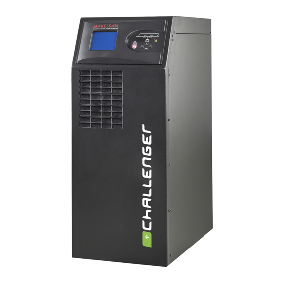
CHALLENGER SERIES 10‐60 KVA PRODUCT DESCRIPTION 2. Product Description General View CH1060TR02R0 AG–SD‐35 Rev. No:1 Rev. Date:25.09.2013 Publication No:2... - Page 10 CHALLENGER SERIES 10‐60 KVA PRODUCT DESCRIPTION Front view CH1060EN03R0 4x20 Karakter LCD Ekran Ventilation Inlets Mimic Diagram Menu Keys EPO (Emergency Power Off) Button AG–SD‐35 Rev. No:1 Rev. Date:25.09.2013 Publication No:2 11...
- Page 11 CHALLENGER SERIES 10‐60 KVA PRODUCT DESCRIPTION Rear view CH1060EN04R0 AG–SD‐35 Rev. No:1 Rev. Date:25.09.2013 Publication No:2 12...
- Page 12 CHALLENGER SERIES 10‐60 KVA PRODUCT DESCRIPTION Rectifier / Charger‐Inverter Cooling Fans Winding Hot Air Evacuation Channel Mains (Input) Breaker Mains (Input) Connection Terminal Ground Connection Input‐Output‐Battery Cable Fixing Terminals Output Connection Terminals Battery Rapid Fuses and Battery Connection Terminals Output Circuit Breaker External ( Maintanance) Bypass Breaker RS232 Terminal for Communication Socket of Rectifier RS232 Terminal for Communication Socket of Inverter Optional card slots Optional card slots Optional Parallel Port Terminal AG–SD‐35 Rev. No:1 Rev. Date:25.09.2013 Publication No:2 13...
- Page 13 CHALLENGER SERIES 10‐60 KVA PRODUCT DESCRIPTION Electrical Connection AG–SD‐35 Rev. No:1 Rev. Date:25.09.2013 Publication No:2 14...
-
Page 14: General Information
CHALLENGER SERIES 10‐60 KVA PRODUCT DESCRIPTION 2.1 General Information ® General operation topology of Challenger Series UPS can be recognized as follows: The UPS is connected to the mains voltage through the CB1 breaker. As DC bus is ramped up, the rectifier starts to operate and converts the AC mains to DC voltage. When the mains voltage is not available, the DC/DC booster pumps the battery voltage to the necessary level.DC DC bus voltage is then converted to mains synchronized AC voltage by the inverter. . This is a high quality voltage. Generated AC power is applied loads after static semi‐conductor switches and output (load) breakers. -
Page 15: Battery Temperature Regulation
NOTE: In the meantime, the loads are unprotected against the power‐off, damage, twist etc. problems. 2.1.2 Battery Temperature Regulation 10‐60 kVA UPSs have their own place for internal batteries. These battery temperature are perceived by "temperature sensor”. UPS adjusts battery charge parameters according to the information of the detected temperature. These parameters can easily be adjusted via LCD or TELNET interface by authorized staff of MAKELSAN. Temperature sensor is given as optional with external battery cabinets. UPS regulates charge parameters in the same way by this sensor. In this case,We recommend you to order "Battery Monitoring Kit" to detect the temperature. 2.2 UPS’s Operation Modes Challeneger series UPS's on‐line and has a double loop structure. Our products operate in the following modes: ... -
Page 16: Battery(Stored) Mode
CHALLENGER SERIES 10‐60 KVA PRODUCT DESCRIPTION 2.2.2 Battery(stored) Mode UPS runs on battery mode when the mains voltage is bad.Battery Voltage is boosted for the sufficient Dc bus voltage. In order to provide proper DC Bus vlotage, battery voltage will be boosted. 2.2.3 Bypass Mode In an overload condition, or if there is a problem with the double conversion, the loads are fed by the bypass line. UPS switches to AC supply from inverter for that by static switches. Inverter must be synchronized with the mains supply for these transitions to be seamless.This transitions might take 15 ms depending on the type of load if inverter output is not synchronized with the mains. 2.2.4 Auto Restart Mode UPS supplies its critical loads up to end of discharge voltage level due to any mains failure. UPS feeds critical loads untill end of battery discharge voltage level caused by any mains failure. Ups will operate until batteries charging process completing after that will be switched off. UPS can operate by itself in specified time after mains turned back to normal mode. In this case, UPS keeps operating proper as long as UPS voltage being in accordance criterias. For Challenger Series UPS, this feature is not activated as factory initial setups. AG–SD‐35 Rev. No:1 Rev. Date:25.09.2013 Publication No:2 17... -
Page 17: Maintenance Mode
CHALLENGER SERIES 10‐60 KVA PRODUCT DESCRIPTION 2.2.5 Maintenance Mode In maintenance mode, the loads are switched to the maintenance bypass line with a breaker, so that the UPS can be serviced without cutting off the power flow to the loads. 2.3 Battery Management Lead – Acid Batteries are used with UPSs as internal with variable configurations. 2.3.1. Normal Operation Mode Constant Charge Current Current is limited to 0.1C untill the float reaches to charge voltage. (adjustable between 0.05C ‐ 0.25C.) The applied current can not exceed maximum charge power. Float Charge Depending on the battery discharge current the third percent energy of the battery is charged at this level. Thanks to this level, batteries are kept ready for use at the highest capacity. For lead‐ acid batteries, this voltage varies between values 2.2‐2.35 V/cell This voltage may differ slightly with temperature adaptation. Option of setting this coefficient is provided with our UPS. If the temperature sensor is used, it is recommended to use. Deep Discharge Protection While the system operates on battery mode, if battery voltage has dropped below the discharge level UPS shuts down and stops absorbing energy from the batteries. This value varies between 1.6‐1.75 V/cell for Lead‐Acid batteries, and for Ni‐Cd batteries between 0.9‐1.1 V / cell. Low Battery Warning While the system operates in battery (stored) mode, according to actual loads if the battery capacity drops below its 40% value, it will give audible and visible alarms. This percentage value is adjustable for user between 20%‐70%. -
Page 18: Advanced Level Functions (Automatic Battery Test)
CHALLENGER SERIES 10‐60 KVA PRODUCT DESCRIPTION 2.3.2 Advanced Level Functions (Automatic Battery Test) The auto battery test discharges 30% of the battery energy in a user defined period (default is 90 days). This period can be adjusted between 30‐360 days. Test reports the battery condition as “good or replace”. Results of the latest test can be seen on the battery screen from the status menu. WARNING: If the test result is “replace”, then the batteries are completely drained during the test. This situation may cause the load remained unpowered in case of mains voltage is out of the limits or mains power off. This test can be started by command from front panel monitor, via TELNET interface, via RS232 smart communication or via MAKNET (SNMP, see the options). It is checked that if the batteries can supply the minimum back‐up time needed in case of the first power‐off by using the results of all these tests. Checking the test results with a regular period is recommended. -
Page 19: User Panel
CHALLENGER SERIES 10‐60 KVA PRODUCT DESCRIPTION 2.4 User Panel User panel consists of mimic diagram, LCD screen, EPO button and menu keys. The UPS can be controlled via this panel. CH1060EN05R0 Rectifier indicator LED Flashes while the DC bus is ramping up. Illuminates when Rectifier works. AC/DC module (Rectifier) Boost mode indicator LED Illuminates in battery mode. Flashes when UPS is started up through batteries. Battery charge indicator LED Illuminates while the batteries are charging. Battery module DC/AC module (Inverter) Mains bypass indicator LED Illuminates while the loads are fed through bypass line. AG–SD‐35 Rev. No:1 Rev. Date:25.09.2013 Publication No:2 20... - Page 20 CHALLENGER SERIES 10‐60 KVA PRODUCT DESCRIPTION Inverter static switch indicator LED Illuminates when the load is fed by the inverter Alarm/Warning indicator LED 10‐ Menu keys 14 EPO (Emergency Power Off ) Button AG–SD‐35 Rev. No:1 Rev. Date:25.09.2013 Publication No:2 21...
-
Page 21: Control Menu
CHALLENGER SERIES 10‐60 KVA PRODUCT DESCRIPTION Menu Flow Chart MAIN SCREEN Manufacturer – Device Name Battery Charge Status as Percent Load Status as Percent Back up (Autonomy) Time Control Menu Status Menu Setup Menu Logging Menu LOGGING STATUS CONTROL SETUP Mains Log Code Start Date & Time Date Output Stop Battery Install Date Bypass Time Output Bypass Auto Restart Log Records Battery Output UPS Auto Battery Test Temperature Quick Battery Test Screen Inverter Battery Status Test Warning Beep DC Bus Stop Battery Test Language Warnings Communication... - Page 22 CHALLEN NGER SERIE S 10‐60 KVA A PRODU U CT DESCRI I PTION 2.4.1 Op pening Scre een ening screen n is on when n the display inte erface is not t being used d. It shows the model nam me, charge an nd load rcentage and d remaining g runtime. In c case of an al arming cond dition, alar rms are show wn on the fi irst row. If n o button is p pressed for 5 minutes, vice returns to the open ning screen.
- Page 23 CHALLEN NGER SERIE S 10‐60 KVA A PRODU UCT DESCRI IPTION 2.4.5 Pa ssword‐pr rotected m menus me menus su uch as the co ontrol menu u are ssword prot tected.Press s up and d down ys to set ea ach digit an nd press EN NTER to c confirm. er level pass sword is “00 000”.
- Page 24 CHALLEN NGER SERIE S 10‐60 KVA A PRODU UCT DESCRI IPTION 2.4.7 Sta atus Menu You can n see inform mation abo ut the main ns, output, bypass lin ne, battery, temperatu re, inverter r, DC bus and d alarms on n this menu. Main VP, A Hz oltage, curre ent and frequ uency of each h phase.. KW, KVA, , PF ctive power, apparent po ower ande po ower factor o...
- Page 25 CHALLEN NGER SERIE S 10‐60 KVA A PRODU U CT DESCRI I PTION 2.4.8 Set tup Menu Setup me nu consists of the follow wing : Date&Tim me To set dat te and time, use up and down keys to choose e the variabl le you want t to set. Then use e up and do own keys to o set the va alue, and press s enter.
- Page 26 CHALLEN NGER SERIE S 10‐60 KVA A PRODU U CT DESCRI I PTION Beeper Turn the b beeper soun nd on/off. Language Set the m enu languag ge. Commun nication Set the p protocol fo r the RS23 32 connecti ion. The options ar re SEC, Meg gatech and T TELNET. Economy y Mode Economy mode (ECO O) and UPS s switch to sta atic...
- Page 27 CHALLEN NGER SERIE S 10‐60 KVA A PRODU U CT DESCRI I PTION 2.4.9 Log gging Men Last 500 events of th he device ca an be seen i the loggin ng menu. When vie wing a log, p press enter to see detailed i nfo about th he UPS. All r recorded data for th hat particul ar event (sta atus, setup etc.) can b be seen on t the menu. Use up a nd down k eys to see older/newe event logs AG–SD‐35...
-
Page 28: Installation
CHALLE ENGER SERI ES 10‐60 KV VA INSTAL LLATION 3. In nstalla ation 3.1 Sin gle Mode I Installatio In this s ection, the w warnings wh hich must b be followed a and the chec cking which h must be pe erformed before s starting‐up t the UPS are e stated. Add ditionally, y you can find d informatio ons about th he points you mus st pay attent tion during caryying sty yle for cabin nets, position ning and con nnections. Warnin ngs The UPS must b be installed... -
Page 29: Positioning
CHALLENGER SERIES 10‐60 KVA INSTALLATION 3.1.2 Positioning Keep the device in a cool and dry place prior to installation. NOTE: Unused batteries must be charged periodically. 3.1.2.1 Positioning The UPS The UPS and the batteries are designed for indoor use, and must be placed on an area with cool air flow. Air enters the device from the front side ventilation holes, goes out from the fans on the rear side of the device. Care must be taken in order not to cover the air enterance and exit spots. If the area is dusty , Optional filters must be used on dusty environments. During operation, there is a remarkable amount of heat loss to room air, so an air conditioning system must be used to keep the temperature in limits. Bridge Load 100% (Non‐lineer) estimated Amount of BTU /h for BTU / h value for load UPS cooling working 10 KVA 3100 3700 15 KVA 4100 5000 20 KVA... -
Page 30: Internal Battery Configuration
CHALLENGER SERIES 10‐60 KVA INSTALLATION 3.1.2.2 Internal Battery Configuration 10‐30 kVA UPS can be configured by 28 ‐50 pcs 7 Ah or 9Ah batteries according to UPS’s power standard as following. Challenger 2 Internal Battery Usage Table 10 15 20 30 UPS Power(KVA) Serial Battery 28 38 40 28 38 40 38 40 38 40 Number 1 2 1 2 1 2 1 2 1 2 1 1 2 1 2 2 2 Battery Group Total Number of 28 ... - Page 31 CHALLENGER SERIES 10‐60 KVA INSTALLATION The batteries’ positioning shapes can be seen at the following table ; 38x2 Battery Set AG–SD‐35 Rev. No:1 Rev. Date:25.09.2013 Publication No:2 32...
- Page 32 CHALLENGER SERIES 10‐60 KVA INSTALLATION CH1060EN07R0 CH1060EN08R0 AG–SD‐35 Rev. No:1 Rev. Date:25.09.2013 Publication No:2 33...
- Page 33 CHALLENGER SERIES 10‐60 KVA INSTALLATION 40x2 Battery Set 51‐54‐52 AG–SD‐35 Rev. No:1 Rev. Date:25.09.2013 Publication No:2 34...
- Page 34 CHALLENGER SERIES 10‐60 KVA INSTALLATION CH1060EN10R0 CH1060EN11R0 AG–SD‐35 Rev. No:1 Rev. Date:25.09.2013 Publication No:2 35...
-
Page 35: External Battery Configuration
CHALLENGER SERIES 10‐60 KVA INSTALLATION 3.1.2.3 External Battery Configuration Batteries should be mounted in an environment where the temperature is consistent and even over the whole battery. Temperature is a major factor in determining the battery life and capacity. The recommended operating temperature for batteries by battery manufacturers is 20‐25 °C . Operating above this range will reduce the battery life while operation below this range will reduce the battery capacity. Therefore ,the expected backup time will not be obtained while autonomy. As a result, keep batteries away from heat sources... - Page 36 CHALLENGER SERIES 10‐60 KVA INSTALLATION THE TABLE OF CHALLENGER SERIES EXTERNAL BATTERY CONFIGURATION UPS Rating (KVA) Total number of Batt. I_char_max@V_bat_max(A) 7,6 6,9 6,3 5,8 11,4 10,4 I_bat_max@V_cut_off(A) Recommended fuse for external cabinet (A) UPS Rating (KVA) Total number of Batt. I_char_max@V_bat_max(A) 12,1 11,6 17.4 I_bat_max@V_cut_off(A) 102 Recommended fuse for external cabinet (A) 125 External battery cabinet and battery room applications are given below as an example. The application form may vary according to the customer. CH1060EN12R0 AG–SD‐35 Rev. No:1 Rev. Date:25.09.2013 Publication No:2 37...
-
Page 37: Transportation Type Of Cabinets
CHALLENGER SERIES 10‐60 KVA INSTALLATION Example Battery Chamber Application CH1060EN13R0 External Battery Cabinet Application 3.1.3 Transportation Type of Cabinets Carrying vehicles or handling accessories must have enough features and characteristics to carry UPS’s weight. Cabinet is equipped with four‐wheel. Thanks to this feature, it can be moved easily. These wheels must be used only on smooth surfaces. The front side wheels of UPS must be locked after positioning properly. The back side wheels are fixed. Be more careful of sudden movements ,especially when batteries are inside of cabinet. Move the UPS as rarely as possible. AG–SD‐35 Rev. No:1 Rev. Date:25.09.2013 Publication No:2 38... -
Page 38: Main,Load And Battery Connections
CHALLENGER SERIES 10‐60 KVA INSTALLATION 3.1.4 Main,Load and Battery Connections MAKELSAN strictly recommends a distribution board for the UPS outputs. Proper fuses and breakers must be used in such distribution board. A‐B type fuses or magnetic breakers are recommended if the load is suitable. 3.1.4.1 External Protection To protect the AC inputs, thermal magnetic breakers or V type breakers must be installed on the distribution board. Over current protecting must be installed on mains input distribution board and fuses must be chosen 135% higher rated than the ones given in the table below. Fuses must be C‐type. Ground leakages flow to the ground through the EMI filters on the input and the output of the UPS. MAKELSAN recommends the use of 700mA rated relays for handling leakage currents. Those relays must also be: ... -
Page 39: Cable Connections
CHALLE ENGER SERI ES 10‐60 KV VA INSTAL LLATION 3.1.4.3 Cable con nnections All elect trical connec ctions of the e UPS are ma ade from th e rear side o of the device e. Remove th he metal cover to o reach the in nput and ou utput connec ctions. ATTE ENTION ! 3 3 pole‐circu uit breaker rs (switch) are used for the in put and outpu ut of UPS, utral line is... - Page 40 CHALLENGER SERIES 10‐60 KVA INSTALLATION Follow the steps below to electrical connections: 1. Make sure that the network and loads are isolated through cables by turning off the all breakers on the distrubution board. CH1060EN15R0 1. Unscrew and remove the metal board on the rear side of the device. CH1060EN16R0 AG–SD‐35 Rev. No:1 Rev. Date:25.09.2013 Publication No:2 41...
- Page 41 CHALLENGER SERIES 10‐60 KVA INSTALLATION 2. Connect the ground cable. CH1060EN17R0 3. Make sure that the circuit breakers are off. The use of these circuit breakers are explained on the operation section. AG–SD‐35 Rev. No:1 Rev. Date:25.09.2013 Publication No:2 42...
- Page 42 CHALLENGER SERIES 10‐60 KVA INSTALLATION 4. Connect the input cables. R to INPUT L1, S to INPUT L2, T to INPUT L3, N(Neutral) to INPUT N. CH1060EN19R0 6. Check the phase sequence. 7. Repeat steps 5‐6 for output cables. 8. Replace the rear board and tighten the screws Use the cable clips to stabilize the cables when the connections are done. WARNING: Make sure that the loads are isolated from the UPS output if they are not ready to be connected. WARNING: Make sure that the cables are connected properly before UPS is started. Additionaly, check if there is galvanic isolation transformers at input of UPS and consider the local directions. WARNING: Check the grounding before starting the UPS. Wrong works or grounding on UPS or other devices of installaton may be hazardous. Wrong works and grounding may damage UPS and another system on the installation.
-
Page 43: Battery Connections
CHALLE ENGER SERI ES 10‐60 KV VA INSTAL LLATION 3.1.4.4 Battery c connection ns You can find explan nations abou ut installatio on procedur es and conn nections of i internal and external l batteries in n this sectio on. ttery Haz zard The b battery term minal voltage e can reach up to 700 V Vdc. Prese erve your ey yes and skin n against pos ssible arcs. Chec k for leaks b before conne ecting the b atteries. - Page 44 CHALLE ENGER SERI ES 10‐60 KV VA INSTAL LLATION Battery y monitorin Inter rnal battery y temperatu re is monit tored by the e NTC conn nected to th he J26 socke et of the main nboard. CH1060E EN20R0 efer to the o options secti ion for exter rnal battery y monitoring 3.1.4.4 .2. Externa al Battery...
- Page 45 CHALLENGER SERIES 10‐60 KVA INSTALLATION 4. Make sure that the batteries are connected properly in series and parallel. 5. Connect the negative battery terminal to –BAT cable, also connect the positive battery terminal to the +BAT cable in the UPS. 6. Check the polarity of the battery connection once again. 7. Replace the battery fuse on the UPS. CH1060EN22R0 8. Replace the battery fuse in the battery cabinet. 9. If any switch breaker exist on the battery cabinet, switch ON them. 10. Please check that whether there is appropriate battery voltage on the input terminals of the battery of UPS by measurement tool.
-
Page 46: Parallel Installation
CHALLE ENGER SERI ES 10‐60 KV VA INSTAL LLATION he external b battery conn nection diag gram is give n below. CH1060E N23R0 3.1.4.5 Control an nd Commu unication C Cable Con nections AKELSAN UP PS have stan dart or opti onal connec ctions of adv vanced exter rnal battery binet, enviro onmental mo onitoring, co ontrol panel ls and variou us intelligen nt monitorin ng. nnections on n the rear si ide of UPS : • On ne RS232 se erial commu unication co nnector (RS S232/Rectifi... - Page 47 CHALLENGER SERIES 10‐60 KVA INSTALLATION Inputs and outputs of more than one UPS are connected to each other; but definitely each battery group is different from another, batteries can not be used in common. The following points should be considered while placement of UPS in parallel system and their electrical connections are made: UPSs connected in parallel must have the same power rating and must be the same series. Devices must be running on the same firmware, if not, old firmwares must be updated. Devices must be located as close as possible to each other (max. 6 x 110 cm paralleling cables.) Each device must have its own neutral cable . Each device must have its own ground connection. UPS must be connected in paralel on the distribution panel and phases must be ...
- Page 48 CHALLENGER SERIES 10‐60 KVA INSTALLATION Parallel Settings Connect the parallel cable as shown in figure below. Only use the cables provided by MAKELSAN. CH1060EN24R0 CH1060EN25R0 * Software settings on the user panel should be made by authorized personel. AG–SD‐35 Rev. No:1 Rev. Date:25.09.2013 Publication No:2 49...
-
Page 49: Operation
CHALLENGER SERIES 10‐60 KVA OPERATION 4. Operation 4.1 Operation Procedure Bu bölümde devre kesiciler, ilk çalıştırma, KGK’nın çalışma tiplerinin testleri, KGK’nın kapatılması, EPO ve RS232 seri haberleşme sistemi hakkında bilgi bulabilirsiniz. 4.1.1 Circuit Breakers These are used for the AC input, maintenance bypass, output and the battery connections respectively. Three‐phase AC voltage is applied through CB1 to input of UPS. AC input voltage will be applied directly to loads through CB2. In this way, maintenance purposed switching is done properly. If UPS is actived while it is working thanks to auxilary short circuit info located in CB3, mains makes the bypass static switches actived. The system will be switched to maintenance mode smoothly. -
Page 50: First Start
CHALLENGER SERIES 10‐60 KVA OPERATION 4.1.2 First Start‐Up WARNING: Wait for at least 5 seconds between each step. 1. Turn the Maintenance (CB2) bypass breaker “ON” CH1060EN26R0 2. Turn the input (CB1) breaker “ON” CH1060EN27R0 AG–SD‐35 Rev. No:1 Rev. Date:25.09.2013 Publication No:2 51... - Page 51 CHALL LENGER SER RIES 10‐60 K KVA O OPERATION Start the UPS using the front panel. “Main men nu> Contro ol > Passw word > Start” Wait for t the operatio on of the rectifier. Rectifier LE ED on the m mimic diagr ram will flash for a w while, and th...
- Page 52 CHALLENGER SERIES 10‐60 KVA OPERATION 8. Verify that batteries are switched via front panel indicator and "Status > Battery" menu. 9. Turn output circuit braker (CB3) ON. CH1060EN32R0 10. Turn the maintenance bypass braker (CB3) OFF. CH1060EN33R0 AG–SD‐35 Rev. No:1 Rev. Date:25.09.2013 Publication No:2 53...
-
Page 53: Testing Of Types Of Ups Operation
CHALLENGER SERIES 10‐60 KVA OPERATION 11. The loads which are connected to UPS can be turned on. After all these steps, check that load is fed through inverter static switches via mimic diagram. In a contrary situation, check UPS total and phase loads. The UPS gives audio alerts in an overload condition, without feeding critical AC loads. 4.1.3 Testing of Types of UPS Operation After first start‐up check device operation by switching between the following modes manually. 4.1.3.1. Switching from Online Mode to Battery Mode Turn CB1 OFF. This action cuts off the mains voltage and the UPS starts operating on battery mode. Turn CB1 back ON again if everything is ok. CH1060EN34R0 AG–SD‐35 Rev. No:1 Rev. Date:25.09.2013 Publication No:2 54... -
Page 54: Main Menu 2
CHALL LENGER SER RIES 10‐60 K KVA O OPERATION 4.1.3.2 2 Switchin ng from On nline Mode e to Static B Bypass Mo ode se the front panel to sw witch the dev vice to static c bypass mo de. Check th he mimic pa nel to make ure that the device has s switched to bypass mod de. Main menu> Control > S Switch to By ypass CH1060 0TR35R0 OTE: UPS w will not switc ch to bypass s mode if the e inverter vo oltage is out t of limits or r there is nd overload d or overtem mperature sit... - Page 55 CHALL LENGER SER RIES 10‐60 K KVA O OPERATION 4.1.3.4 4 Switching g from Onl line Mode to Mainte nance Byp pass Mode WARNING: Make sure that the inv erter output t is synchro nous with th he maintena ance bypass line before s switching to o maintenan nce bypass m mode. Other wise there i is a possibili ity of cutting off t the load pow wer for a sho ort while. Use the fron nt panel to s switch the de evice to stat tic bypass m mode. Check the mimic p panel to make sure t that the devi...
- Page 56 CHALL LENGER SER RIES 10‐60 K KVA O OPERATION 2. Stop the UPS by using front panel. in menu > C Control > Sto 3. Turn n CB1, CB3 a and CB4 OFF 1060EN39R0 WARNING: Wait at least 5 min nutes before e opening u up the devic c e after it is s complete ly turned off, for s safety AG–SD‐ 35 Rev. No: 1 Rev. Date: :25.09.2013 Publication n No:2...
-
Page 57: Epo (Emergency Power Off)
CHALL LENGER SER RIES 10‐60 K KVA O OPERATION 4.1.4 P Perfoming a Complet te Shut Do 1. Turn off t the loads co nnected to t the device. Main n Menu> Control> > 2. Use the front panel to turn the e device OF FF by follow wing, “ Password d> Stop”. RNING : Mak ke sure that t there are no critical... -
Page 58: Rs232 Serial Communication Installation And Investigation
CHALLENGER SERIES 10‐60 KVA OPERATION 4.1.6 RS232 Serial Communication Installation and Investigation Challanger series has an RS‐232 interface which supports SEC and TELNET protocol as standart.This interface is fully isolated and safe. UPS can be monitored remotely via a computer (PC) or SNMP by using this protocol. This connection works with all kinds of options. AG–SD‐35 Rev. No:1 Rev. Date:25.09.2013 Publication No:2 59... -
Page 59: Explanations Of Logging
CHALLENGER SERIES 10‐60 KVA EXPLANATIONS OF LOGGING 5. Explanations of Logging UPS will beep when any problem is detected. You can see the first information about the situation on the front monitor panel. This may not be enough most of the time. In this case, you can see the following warnings by using log screen. Warning Warning Description RS232 Start Command UPS was started by RS232 communication software. RS232 Stop Command UPS was stopped by RS232 communication software. After the batteries discharge totally, UPS restarted itself Auto Restart automatically after the mean time which adjusted that UPS Startup The main board of the UPS is energized. Soft Start Fail UPS could not ramp the DC bus up. Quick Battery Test Quick battery test has began. Deep Battery Test Battery capacity test has began. Battery Self Test Periodical battery test has began. Batteries’ voltage has gone below cut off voltage value while End Of Discharge UPS was operating on the battery mode. UPS has operated at overload more than time limit adjusted. Overload Timeout The Loads will be transferred to bypass line. Battery test has completed. You can see the all results via End of Battery Test front panel status menu. Test was aborted manually or by UPS since the criterias Batt. Test Aborted were not provided during battery test. Static switchs directions were changed manually to the Manuel Switch To BYP bypass line via UPS command menu. - Page 60 CHALLENGER SERIES 10‐60 KVA EXPLANATIONS OF LOGGING Maint. BYP. Sw. On Maintenance bypass switch has been activated. The ambient temperature is over limit. Check the ventilation Ambient Abnor. Temp. of UPS room. UPS battery charge current is out of the specified limits. Battery over‐current Charge will be OFF until return to normal operating. Mains voltage is out of the specified limits, UPS will switched Mains Voltage bad to battery mode. Inverters temperature is out of limit, in case of 5 degrees more Inverter Overtemp. increment, Load will be transferred to Byp line Rectifier 's temperature is out of limit, in case of 5 degrees PFC Overtemp. more increment ,Load will be transferred to Bypass line. Charge / boost module temperature is out of the specified Chrg OverTemp. limits. If it is in charge mode, Charge will be stopped. If it is in boost mode, UPS will be stopped. Static Transfer Switches’ temperatures are out of limits. UPS STS Overtemp. will be stopped. Outp.PL1 Cur. Limit. Short circuit protection is activated for output L1 phase. Outp.PL2 Cur. Limit. Short circuit protection is activated for output L2 phase. Outp.PL3 Cur. Limit. Short circuit protection is activated for output L3 phase. Bypass voltage value is out of limit while UPS was operating Bypass Voltage Bad on the bypass mode. UPS will switch to normal mode if temperature and load status are normal.If not ,UPS will stop. Bypass frequency value is out of limit while UPS was Bypass Freq. Bad operating on the bypass mode. UPS will switch to normal mode if temperature and load status are normal.If not ,UPS Over temperature is observed for UPS’ inverter and rectifier Coil Overtemp...
- Page 61 CHALLENGER SERIES 10‐60 KVA EXPLANATIONS OF LOGGING Output load value is over %105, overloading counter will Overload start to count, If UPS is on normal mode, the charging will be stopped until load value gets back to normal. Maint. BYP. Sw. Off Maintenance bypass switch is deactivated. UPS ambient temperature has got back to allowed limit Ambient Nor. Temp. values. Mains voltage is in the limited values, UPS will switch to Mains Voltage Nor. normal mode. Inverter temperature is in the limited values. If load and Inverter Nor. Temp. temperature values are normal, UPS will switch to normal Rectifier temperature is in the limited values. If load and PFC Nor. Temp. temperature values are normal, UPS will switch to normal Charger/booster module temperature is in the allowed Charger Nor. Temp. limits, charging will be activated again. Temperature of Static transfer switches is in the allowed STS Nor. Temp. limit. Bypass Voltage Nor. Bypass voltage is within defined limits. Bypass Freq. Nor. Bypass frequency is within defined limits. UPS inverter or rectifier coil temperature has got back to Coil Normal temp. normal values. Inverter voltage is in the limited values, UPS will switch to Inverter Volt. Norm. normal mode. Output load is under %100, If charging was OFF, It will be Normal Load ON . UPS has detected short circuit at bypass L1 thyristor. UPS BYP Thyr.L1 Short C.
- Page 62 CHALLENGER SERIES 10‐60 KVA EXPLANATIONS OF LOGGING UPS has detected short circuit at inverter L2 thyristor. UPS UPS Thyr.L2 Short C. will shut down. UPS has detected short circuit at inverter L3 thyristor. UPS UPS Thyr.L3 Short C. will shut down. UPS has detected that inverter L1 thyristor can not be UPS Thyr.L1 Open C. activated. Load will be transferred to bypass line. UPS has detected that inverter L2 thyristor can not be UPS Thyr.L2 Open C. activated. Load will be transferred to bypass line. UPS has detected that inverter L3 thyristor can not be UPS Thyr.L3 Open C. activated. Load will be transferred to bypass line. UPS has detected that bypass L1 thyristor can not be BYP Thyr.L1 Open C. activated. Load will be transferred to inverter line. UPS has detected that bypass L2 thyristor can not be BYP Thyr.L2 Open C. activated. Load will be transferred to inverter line. UPS has detected that bypass L3 thyristor can not be BYP Thyr.L3 Open C. activated. Load will be transferred to inverter line. One or more of UPSs which operate in paralel mode do not Parl. Phs. Rot. Err. match in phase sequence. Battery Start Starting through battery command has been given to UPS. One or more of UPSs which operate in paralel mode could Parl. Start Error not start to operate. Inverter Fault UPS couldn't prepare the inverter voltage. Static transfer switches all disabled. The loads can not be Output Off energized. UPS is operating in the normal mode, load are energized Normal Mode through rectifier – inverter line.
- Page 63 CHALLENGER SERIES 10‐60 KVA EXPLANATIONS OF LOGGING 2 or more UPS are operating in power sharing mode. Load is Parallel Mode fed through UPSs’ inverter lines. UPS has switched to battery test mode, loads are energized Test Mode through rectifier‐ battery‐ inverter line as source sharing. KGK eko moddan çalışıyor. Yükler bypass hattı üzerinden EKO Mod besleniyor. The direction of the static switches was varied manually on Switch to Inverter Command the rectifier through UPS commands menu. Output voltage is detected during the period of starting UPS . Output Voltage Error UPS has been stopped. Abnormal stuation is detected during the moment of PFC Stop Cmd. rectifier operating.UPS has stopped itself. Manuel Start Command Start command is given via UPS command menu. Manuel Stop Command Stop command is given via UPS command menu. An error occurred while ramping up the battery bus, Batt. Swtch. Failure Batteries could not be activated. UPS Stopped UPS has been stopped. UPS has switched to bypass mode so many times i a short Bypass Problem period, UPS will be shut down. Device‐related parameters were changed on the service Parameters Changed menu Battery replacement date has been changed. Battery Batterys Changed statistics will be reset. Battery mechanical switch on the service menu was Battery Contactor OFF deactivated. Batteries are not active.
- Page 64 CHALLENGER SERIES 10‐60 KVA EXPLANATIONS OF LOGGING Slave UPS which is operating in paralel mode can’t reach to No P.CAN Bus Comm. master UPS from CAN bus. If UPS is operating, will be shut UPS which is operating in paralel mode has been given a Ext. Start Command command to start up by another (master) UPS. UPS which is operating in paralel mode has been given a Ext. Stop Command command to stop by another (master) UPS. UPS which is operating in paralel mode has been given a Ext. Switch To BYP. command to transfer the load to bypass line. UPS which is operating in paralel mode has been given a Ext. Switch To UPS command to transfer the load to inverter line. Slave UPS which is operating in paralel mode has detected a Parallel Comm. FE. failure of input current sharing. Inverter voltage reached needed value after UPS is started Inverter OKEY up. UPS can feed the loads through inverter. Battery temperature is out of defined limits, batteries can be Batt. Temp. Err. damaged. Booster Overcurrent Overcurrent in Battery mode, UPS will be shut down. EPO key pressed EPO key button is pressed. Battery capacity has decreased below defined “ battery low Battery Low limit” while UPS was operating in battery mode. Parallel RS485 communication between the systems is not No P.485 Bus Comm. available. STS OverCurrent OverCurrent in Bypass line. UPS output breaker is turned off. Loads can not be Output Signal OFF energized.
- Page 65 CHALLENGER SERIES 10‐60 KVA EXPLANATIONS OF LOGGING Battery Temp. Nor. Battery temperature is normal. Output Signal ON UPS output switch is opened. Loads can be energized. Able to communicate with the fan control system. Only for 100 Fans Active UPSs that contain the fan control system. 101 PFC Pbus OverVoltage Positive DC Bus overvoltage. 102 PFC Nbus OverVoltage Negatif DC Bus overvoltage 103 PFC PhL1 OverCurrent Short circuit protection is activated for rectifier L1 phase. 104 PFC PhL2 OverCurrent Short circuit protection is activated for rectifier L2 phase. 105 PFC PhL3 OverCurrent Short circuit protection is activated for rectifier L3 phase. Command to stop itself has been given to UPS which is 106 Single Stop operating in paralel mode separately from paralel system. 107 Master Changed UPS became master device in paralel system. ID value of one or more UPS is the same as each other in 108 Par. Bus ID Collision parallel system. One or more phase of slave UPS’ output is not connected to 109 Output Offset Err. master UPS in Parallel systems. Short‐circuit current limit has been exceeded in the 110 Bypass Short Circuit...
- Page 66 CHALLENGER SERIES 10‐60 KVA EXPLANATIONS OF LOGGING Alarms and Descriptions Decription of Alarm Alarm Over Temperature at the UPS units, Check the Status> Over Temperature Temperatures menu UPS is overloaded, reduce the load. Over Load Bypass line voltage or frequency is out of limits, can not be Bypass Bad bypassed. UPS Stopped The charging circuit problem is detected, batteries can not be Charge Failure charged. In the case of mains interruption, critical loads remain energized. Fan control board can not be reached, control will not be made. Fan Failure Output Fuse is turned OFF. Fuse Failure Stop command was given to the UPS, UPS will shut down at the end Shutting Down of the period. No battery detected. No Battery Maintenance bypass fuse is ON. M. Byp. Sig. Active UPS feeds the critical loads via bypass line. Static. Byp. Mode UPS is operating in the battery test mode. Test is progressing At the end of the battery test, battery capacity was found to be Replace the batteries insufficient. Critical loads remain energized, In the case of mains interruption. Inverter voltage can not be created. Inverter Fault UPS switched to battery mode. Battery Mode There is more than one UPS with the same ID number at the system Parallel. ID Conflict...
- Page 67 CHALLENGER SERIES 10‐60 KVA EXPLANATIONS OF LOGGING The battery capacity has fallen below defined limit in battery mode. Low Battery UPS is operating in ECO mode. EKO Mode One or more thyristor is faulty. See the history logs for details. Thyristor Failure Bypass line phase sequence is not compatible with inverting the BYP. Phase Rot. Err. phase sequence. Number of perceived UPS at the parallel system is not the same as Par. UPSMissing number of set UPS. One or more other phase of UPS is energized as different from other Curr. Char. Err UPS. One of the power supplies that operates in paralel stopped. Power Supply Failure UPS switched to generator mode. Switching to generator mode Generator Mode command was given by dry contact board. AG–SD‐35 Rev. No:1 Rev. Date:25.09.2013 Publication No:2 68...
-
Page 68: Technical Specifications
6. Technical Specifications Technical Specifications 10kVA 15kVA 20kVA 30kVA 40kVA 60kVA Power 8kW 12kW 16kW 24kW 32kW 48kW Active Power Input Input Voltage Range 220 ± %15 (L‐N) or 380 ± %15 (L‐L) 3P + N + PE Input Power Factor At Full Load > 0,99 Input Frequency Range 50Hz ± 10% / 60Hz ± 10% (Adjustable) Rectifier IGBT Rectifier Total Harmonic Distortion <%5 (THDi) Output 220/380 VAC (230/400 VAC adjustable) 3P + N ± 1% Static, ± 1% Output Voltage Range Dynamic At 0% ‐ 100% ‐ 0% load, maximum output tolerance %5, %1 Back to Recovery band <40ms Efficiency Up to %93 synchronous with the network at the range of 50Hz ±2% , mains Output Frequency Range... -
Page 69: Operation 5
Communnication Communication adapter option RS232 Standart, RS485 and SNMP Dry Contact Optional Protocol Megatec, SEC, TELNET Certificates Quality ISO 9001 Standard CE, TSE Safety TS EN 62040‐1‐1, IEC60950 EMC/LVD TS EN 62040‐2; A Class General Running Temperature At the range of 0 °C ~40 °C (for batteries 0 ~ 25 °C) Storage Temperature At the range of ‐15 °C ~ 45 °C (for batteries ‐10 ~ 60°C) Protection Class IP20 Chassis Anti‐Static Paint Protection Humidity 0‐95 % <1000m, Correction Factor 1. <2000m, Correction Factor >0,92, <3000m; Altitude Correction Factor >0,84 Acoustic Noise (1m) 60dBA 65dBA 500Event Log. (Optional Status Record) Log Recording Parallel Operation Parallel power increase up to 8 pcs. EPO (Emergency Power Off) Standard Isolation Transformer Optional... -
Page 70: Contact Informations
CHALLENGER SERIES 10‐60 KVA CONTACT INFORMATION 7. CONTACT INFORMATIONS www.makelsan.com.tr İstanbul Deri Organize Sanayi Bölgesi 2. Yol, I ‐5 Parsel, 34956 Tuzla/ İstanbul Tel: 0216 428 65 80 Faks: 0216 327 51 64 e‐mail: makelsan@makelsan.com.tr İzmir Şube: Hakapınar Mah. 1348 Sok. 2AE Keremoğlu İş Merkezi Yenişehir – İzmir Tel: 0232 469 47 00 Faks: 0232 449 47 00 e‐mail: izmir@makelsan.com.tr AG–SD‐35 Rev. No:1 Rev. Date:25.09.2013 Publication No:2 71... - Page 72 İstanbul Deri Organize Sanayi Bölgesi 2. Yol, I ‐5 Parsel, 34956 Tuzla/ İstanbul Tel: 0216 428 65 80 Faks: 0216 327 51 64 e‐mail: makelsan@makelsan.com.tr İzmir Şube: Hakapınar Mah. 1348 Sok. 2AE Keremoğlu İş Merkezi Yenişehir – İzmir Tel: 0232 469 47 00 Faks: 0232 449 47 00 e‐mail: izmir@makelsan.com.tr...
Need help?
Do you have a question about the Challenger Series and is the answer not in the manual?
Questions and answers