Table of Contents
Advertisement
Advertisement
Table of Contents

Related Manuals for BENETEAU OCEANIS 58


Summary of Contents for BENETEAU OCEANIS 58
- Page 1 OCEANIS 58 Owner's Manual Code: 119968 Index F...
-
Page 3: Welcome Aboard
The whole BENETEAU team welcomes you aboard. A BENETEAU is made to last, in order to bring you all the pleasure you expect from a vessel over a period of many years. Each boat is subject to the utmost attention to detail from the design stage right through to launching. - Page 5 The boat must have on board all the proper safety equipment (lifejackets, The BENETEAU shipyards may not be held responsible for any alterations buoys, harness, flares, liferafts, etc.) depending on the type of vessel, its which they have not approved.
- Page 6 ARNING So as to be able to continuously improve their product the BENETEAU shipyards reserve the right to make any alterations in Indicates the existence of a danger which could lead to injury or design, layout or equipment which they judge necessary.
- Page 7 Introduction HISTORY OF UPDATES •Index A................12/2009 •Index B................09/2010 •Index C ................03/2011 •Index D ................08/2012 •Index E................01/2014 •Index F................06/2014...
- Page 9 ..............Introduction 7 .......... General specifications 13 ..............Safety 31 ..............Hull 35 ..............Deck 47 ..........Steering system 55 ..........Rigging and sails Contents 73 ..............Interior 79 ........Water and sewage water 95 ........... Electrical equipment 10 10 129 .............. Engine 11 11 159 ............
-
Page 11: General Specifications
General specifications Technical specifications Certification Design category Your boat... - Page 12 E ............6,90 m Total mass of liquids (all tanks full) .......... 2 184 kg The sails are the main propulsion means of the OCEANIS 58. Freshwater capacity ..............2 x 324 l Note: The capacities indicated are maximum (including Freshwater capacity additional............
- Page 13 C - "Near to the coast" Up to and including 6 Up to and including 2 D - "In sheltered waters" Up to and including 4 Up to and including 0,3 The OCEANIS 58 model conforms to the directive 2003/44/CE...
- Page 14 Category A: At high sea Category D: In sheltered waters This craft is designed to operate in winds that may exceed wind force 8 This craft is designed to operate in winds up to Beaufort force 4 and the (Beaufort scale) and in significant wave heights of 4 m and above. associated wave heights (occasional maximum waves of 0,5 m height).
- Page 15 Engine type Serial number Engine key number BENETEAU (Establishment of the company SPBI) Z.I. des Mares - BP 66 - 85270 St - Hilaire - de - Riez - FRANCE - Tèl. + 33 (0)2 51 60 50 10 - http://www.beneteau.com...
- Page 17 Safety Safety Equipment General information Gas system Recommendations for gas Fight against fire Bilge pump system Emergency tiller...
- Page 18 AFETY QUIPMENT Designation Position of swimming ladder (means of coming back onboard) Location of liferaft locker Swimming ladder (means of coming back onboard) Storage locker for liferaft (not supplied) (Reference 1) (Reference 2) Open position Closed position Locker open Locker closed Safety...
- Page 19 Safety ENERAL INFORMATION ANGER DANGERS - Fuel leaks or vapour represent a danger of fire and The major hazards concern: explosion. - Leave the engine compartment ventilated for a long - The gas system. time before starting the engine. - There may be danger of fire or explosion if direct - The electrical system.
- Page 20 AS SYSTEM OCATION 1. Gas cylinder locker 2. Vent hole 3. Drain 4. Gas system 5. Supply valve - Gas Note: Same position for the other layouts. Supply valve: Valve A pictogram helps to Cooker - Oven Gas cylinder locker 6 - Open position locate it easily Under Cooker...
- Page 21 Safety ECOMMENDATIONS FOR GAS ARNING Type of cylinder: butane, service pressure 10 kg/cm or according to current standards of your country). Close the valves on the system and on the cylinder when the appliances are not used. Close the valves -Don't use a solution containing ammonia.
- Page 22 CHEMA ERSION UROPE Designation Regulator valve Gas cylinder Drain Connection kit gas bottle Rubber washers Pictogram Connection kit gas copper PVC girdled sleeve Gas appliance connection kit Safety...
- Page 23 Safety CHEMA ERSION US Designation Regulator valve 12V Gas cylinder Drain Stuffing box PVC girdled sleeve Electromagnetic valve for gas 12V Pipe Propane Plastic...
- Page 25 Safety Regularly check and replace the rubber tubings that link the cylinder to one end of the circuit and the stove to the other one, depending on the norms and regulations in force in your country. ARNING Pay particular attention to keep in good condition the screw thread of the cylinder on which the regulator is.
- Page 26 MERGENCY EVACUATION AND LOCATION OF EXTINGUISHERS Emergency exits in case of fire - Deck hatch - Skipper's cabin - Deck hatch of the fore cabin - Companionway ROCEDURE TO EXIT THROUGH THE FORWARD CABIN DECK HATCH 1. Remove the mattresses and the deck panel. 2.
- Page 27 -Clear the area immediately after use in The extinguishers must be in position (see "Extinguisher positions" diagram). order to avoid suffocation. Extinguisher, per unit, minimum capacity 5A/34B. -Air before entering. For the OCEANIS 58: 25A/170B(equivalent 5 extinguishers of this minimum capacity).
- Page 28 OSITION OF FUEL VALVE AND ENGINE COMPARTMENT EXTINGUISHER APERTURE Extinguisher hole located under A pictogram helps to locate it Supply valve Fuel the companionway step easily On the Port tank On the Starboard tank Safety...
- Page 29 Safety The engine compartment has a port that makes it possible to inject the extinguishing product inside without opening the usual access hatches. NSTRUCTIONS TO FOLLOW IN CASE OF A FIRE IN THE ENGINE COMPARTMENT BILGE - Stop the engine. - Switch off power and stop fuel supply.
- Page 30 SE OF THE MANUAL BILGE PUMP Operation Location Capacity: 40,5 litre / minute Safety...
- Page 31 Safety ILGE PUMP SYSTEM ARNING ROCEDURE TO BE FOLLOWED - Switch on power to the electric bilge pumps. -The bilge pump system is not designed to - If necessary activate the manual pump. provide buoyancy to the boat in case of damage.
- Page 32 SE STEERS FRANK OF HELP Sector access port Tiller in position Safety...
- Page 33 Safety MERGENCY TILLER DVICE ECOMMENDATION The emergency tiller is in an aft locker and shall be easy to get to. To operate the tiller: -The emergency tiller is designed only to - Use a winch handle and unscrew the tiller cover situated at the back of the cockpit. be able to continue underway at a reduced speed in case of steering gear - Insert the tiller into the rudder stock and make sure it is fully secure in the square.
- Page 35 Hull Maintenance of the Hull Lifting...
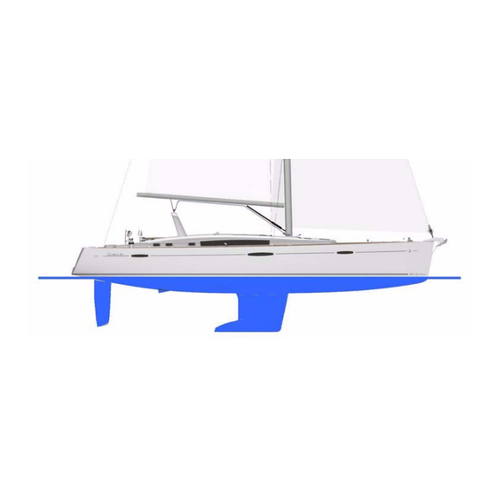
- Page 36 IFTING Wetted area : 80 m² (All versions) Hull...
- Page 37 Hull AINTENANCE OF THE RECAUTION The materials and equipments of your boat have been selected because of their high quality and performance and ease of maintenance. However you shall carry out a minimum maintenance in order to -Consult the harbourmaster's office to find out protect your boat from outside attacks (salt, sun, electrolysis ...).
- Page 39 Deck Navigation - Deck Layout Stability Prevention of man overboard Mooring lines Towing Mooring Maintenance of the Deck...
- Page 40 NAVIGATION - DECK LAYOUT A. Mooring cleats Jack-lines to be fixed to the mooring cleats B. Towing: - at the bow, to be towed - at the stern, to tow C. Swimming ladder (means of coming back onboard) D. Mount Outboard (not supplied) E.
- Page 41 Deck TABILITY Breaking waves represent a serious danger for stability and for taking in water. Close the companionway ANGER doors and hatches in heavy seas. During sailing keep all the portholes, windows and doors closed. -Wear your life jacket. - The stability is reduced when you add weight in the upper parts. -In heavy weather, wear your safety harness and fasten yourself to the boat.
- Page 42 Opening mechanism / Closure To unlock (upward / Companionway - Manual) Opening hatch Location: Technical room Location: Cockpit table 1. Control (upward and downward motion) 2. Key - Locking 3. Remote control Access - Cockpit To unlock upward / Companionway Manual Must be secured while sailing Location: Cockpit locker - forward Access...
- Page 43 Deck Cockpit table...
- Page 44 Rope locker Hydraulic gangway - Rotary PERATION The gateway combines the functions of gateway and davit. Maximum permitted load: 110 kg: 250 kg. Open length: 2,70 m. ARNING -Refer to the manufacturer's instructions for use and maintenance. Deck...
- Page 45 Deck OWING OWING BOAT ARNING - Tow another boat at a reduced speed and as smoothly as you can. Windlass operations are dangerous: - Pay particular attention when you throw or catch the towing rope (it may foul on the propeller). -Always keep the anchor chain or rode free Note: The stability may be reduced when you tow a boat.
- Page 46 LECTRIC WINDLASS REAKER Access: Mooring locker - Skipper's cabin 1. Bow fitting 2. Windlass 24V 2000W 3. Handle position 4. Smooth gypsy head 5. Chain rim - 12 mm diameter 6. Clinch 7. Mooring locker 8. Remote control Breaker - 125A Location Location: Port aft cabin Battery switch...
- Page 47 Deck NCHORING BY HAND WITH USE OF A MANUAL WINDLASS NCHORING BY HAND WITH USE OF A MANUAL WINDLASS - Release the windlass brake using the handle located in the chain locker so as to allow the chain lifter to - Release the windlass brake using the handle located in the chain locker so as to allow the chain lifter to DVICE ECOMMENDATION...
- Page 49 Deck AINTENANCE OF THE RECAUTION Preferably wash your boat on shore. Use as few cleaning agents as possible. -Consult the harbourmaster's office to find Don't use solvents or aggressive detergent agents (Refer to chapter 3 "Hull"). out the conditions of water use and the Don't discharge cleaning agents into the water.
-
Page 51: Steering System
Steering system Steering Gear... - Page 52 TEERING Steering system...
- Page 53 Steering system Detail B Detail C...
- Page 54 Detail D Steering system...
- Page 55 Steering system Designation Rudder Stock Lower fret - 170 mm diameter Upper fret - 120 mm diameter Balance bush Bronze bush - 170 mm diameter Rudder port tube Stock seal Rudder port tube Alignment bearing - Upper Bronze bush - 120 mm diameter Sector Mount - End stop End stop...
- Page 56 Steering Gear Sheaves Sector Access: Deckhead - Aft cabin Access: Deckhead - Aft cabin Access: Compartment - Aft quarterdeck Steering system...
- Page 57 Steering system TEERING ARNING AINTENANCE -Learn how to judge the necessary - Regularly check: • The tension in the steering cables. distance of deceleration for the vessel to • The tightness of the steering system components. come to a complete stop. - Don't tighten the steering cables excessively.
-
Page 59: Rigging And Sails
Rigging and sails Standing rigging Running rigging Winches Setting the sails Sails... - Page 60 LL VERSIONS Rigging Backstay Forestay V3D4 Optional equipment: Fore stay Rigging and sails...
- Page 61 Rigging and sails TANDING RIGGING ANGER Your BENETEAU dealer was responsible for stepping the mast of your boat. -To hoist a crew member up to the top of the mast, make a bowline with the halyard After masting your vessel and after having sailed for the first time it is necessary to seek the help of a directly on the bosun's chair ring qualified specialist in order to carry out a rigging check.
- Page 62 ENERAL HANDLING DIAGRAM LASSICAL MAST Designation Main halyard Mainsail foot Reef 1 Mainsail sheet Kicking strap Reef 2 Reef 3 Spinnaker halyard Fore stay sail halyard Staysail sheet Genoa furler line genoa car adjustment Genoa sheet Spinnaker sheet Rigging and sails...
- Page 63 Rigging and sails AST FOOT SYSTEM LASSICAL MAST ORT SIDE TARBOARD Designation Designation Main halyard Spinnaker halyard Kicking strap Reef 2 Mainsail sheet Reef 3 Mainsail foot Fore stay sail halyard Reef 1 Staysail sheet...
- Page 64 AINSAIL CLASSIC SYSTEM LASSICAL MAST Designation Kicker tackle Single pulley Mainsail sheet Pulley Rigging and sails...
- Page 65 Rigging and sails UNNING RIGGING ARNING AINTENANCE -Refer to the manufacturer's instructions to Lightly grease the sheave pins. Change any distorted or dented sheave. Inspect the pins of the sheaves at the top of the mast once a year. remove the winches and put them back. -Improper refitting may result in accidents Regularly check the condition of the jam cleat jaws.
- Page 66 ENOA SYSTEM Designation Genoa sheet Genoa furler line Stanchion fairleads Single pulley - 57 mm diameter Rigging and sails...
- Page 67 Rigging and sails TAYSAIL SHEET ORE STAY SAIL FURLER Designation Designation Traveller Forestay sail furler line Staysail sheet Releasable fore-stay chain-plate Swivel single pulley - 57 mm diameter Stanchion block Track - Staysail Stanchion fairleads Rail end piece Single clutch Swivel single pulley - 57 mm diameter Single pulley - 57 mm diameter...
- Page 68 TAYSAIL TAKE UP DRUM Designation Staysail take-up drum Releasable fore-stay chain-plate Swivel plates Single pulley (On sandow) Rigging and sails...
- Page 69 Rigging and sails URLING GENOA ITTING - Secure the head and halyard to the swivel. Secure the tack to the drum and sheets. DVICE ECOMMENDATION - Insert the bolt rope into the hole and hoist it and take care that you do not tear it. -When you are not sailing, slacken the - Have the halyard taut enough but hoist less taut than a sail on a normal stay.
- Page 70 YSTEM Designation Furling line - Staysail take-up drum Bobstay Swivel plates Spinnaker sheet Spinnaker halyard Swivel single pulley - 100 mm diameter Tackle block Single pulley (On sandow) Rigging and sails...
- Page 71 Rigging and sails YSTEM SYMMETRIC SPINNAKER Designation Single pulley - 100 mm diameter Spinnaker sheet Spinnaker tack (On Cleat) Spinnaker halyard Bobstay...
- Page 72 ASY SAIL Designation Genoa car Double blocks Rail end piece - Mainsail (classic) Track Rail end piece - Genoa Rail end piece Genoa sheet genoa car adjustment Single pulley - 75 mm diameter Piston - Backstay Cable adjustment - Hydraulic - Backstay Rigging and sails...
- Page 73 Rigging and sails AILS DVICE ECOMMENDATION The working life of a sail mainly depends on its being regularly maintained. -At the end of the sailing season, and if When sailing, trim the sails properly in accordance with the stresses in order to reduce the harmful strains possible before winter, leave your sails to on the fabric.
- Page 74 UTOMATIC REEFING SYSTEM Rigging and sails...
- Page 75 Rigging and sails LEANING AND MAINTENANCE Rinse the sails with fresh water from time to time and dry quickly in order to avoid mildew. Avoid drying the sails to windward when on the mast (when the sails lift, the seams are worn, the sails may be torn by the rigging). AULING DOWN THE STANDARD MAINSAIL To haul down the mainsail: - Haul up.
- Page 77 Interior Introduction Interior maintenance Maintenance of fabrics...
- Page 78 NTRODUCTION Version 3 cabins + Forepeak cabin Version 4 cabins + Forepeak cabin Interior...
- Page 79 Interior NTERIOR MAINTENANCE NTERIOR RECAUTION - Take advantage of the fine weather to take the settee and berth cushions out. -For the PVC fabrics, don't use any solvent - Put the cushions vertically if you leave the boat for long. or solvent based product (pure alcohol, - Use blinds to protect the inside of the boat against UV rays.
- Page 80 Suction-cup system to lift floors Open Closed Interior...
- Page 81 Interior 100% POLYESTER RALON JACQUARD If you cannot remove the fabric: - Clean with the vacuum cleaner. - Clean with a foam for synthetic fabrics (please refer to the product instructions). If you can remove the fabric: - Hand wash with an ordinary washing powder at 30° C. In both cases, dry cleaning is possible.
- Page 83 Water and sewage water Water tanks Water system - Distribution Water system - Drainage Sewage...
- Page 84 ATER TANKS OCATION Tanks Location: Saloon Gauge Capacity: 2 x 324 litre Location: Electrical panel Extra tank Refer to the instructions for use Location: Forward cabin Capacity: 330 litre Deck filler Water and sewage water...
- Page 85 Water and sewage water ATER TANKS ARNING PERATION In order to prevent any handling mistakes, never fill the water and fuel tanks at the same time. -The tanks' nominal capacity cannot be fully used due to the load and the need to During filling, avoid handling contaminants near the fillers.
- Page 86 LUMBING BOARD Location: Port saloon Water heater 1. Supply - Starboard tank 2. Supply - Port tank 1. Water heater 60L 220V 3. Supply - Forward tank (additional) 2. Thermostatic mixer valve 4. Water pump 24V Water and sewage water...
- Page 87 Water and sewage water ATER SYSTEM ISTRIBUTION SE OF THE WASHBASINS AND SHOWERS ARNING - Close the valves and turn off the taps after use. -Turn off the shore freshwater supply valve EAWATER PUMP RESH WATER before leaving the vessel. The pump can have sea water or fresh water to the sink.
- Page 88 OCKPIT SHOWER SPRAY Location 1. Mixer tap 2. Shower HORE FRESHWATER SUPPLY Selection valve - Location Shore fresh water / On board water circuit Location: Starboard saloon EA WATER DECK WASH PUMP Pump for deck Seawater inlet Connection Location washing + Filter (Ref 2) (Ref 3) (Ref 1)
- Page 89 Water and sewage water ATER SYSTEM RAINAGE ARNING PERATION Waste water from the sink, washbasins and heads is drained off by thru-hull fittings with ball valves (the -Turn off shore water before leaving the valve is closed when the valve handle is perpendicular to the hose, the valve is open when the valve handle vessel..
- Page 90 Washbasin draining Shower draining - Valve layout Sink draining - Galley Aft washroom - Port and starboard Access - Galley floor Location: under the washbasin Control - Draining pump for shower Draining pump for shower Shower - Port aft Forward shower + Washbasin (Ref 1) (Ref 2) Location: Under cabinet bathroom...
- Page 91 Water and sewage water SE OF TOILETS UIET LUSH 1. Rinsing out the bowl 2. Water filling to the left and bowl draining to the right Layout of components: Under cabinet bathroom 1. Sea water filter 2. Electric pump quiet flush The electric toilets operate with seawater only.
- Page 93 Water and sewage water EWAGE DVICE ECOMMENDATION SE OF THE MARINE HEADS -When you are in a marina, use the club- Before you use the heads, check that the water intake valve and draining valve are open. house sanitary facilities (if there are). To empty the bowl: -Since it is prohibited to discharge sewage - Set the control lever of the pump slantwise (FLUSH).
- Page 94 Seawater inlet - WC - Valve layout WC - Port aft (Ref 1) WC - Starboard aft (Ref 2) WC - forward (Ref 3) WC - Skipper (Ref 4) Water and sewage water...
- Page 95 Water and sewage water Black water circuit - Schematic diagram Deck or sea evacuation Deck only evacuation 1. Deck filler - Suction and Rinsing 1. WC 2. Tank vent hole 2. Seawater inlet 3. Thru-hull seacock 4. Sewage tank 5. Closing cap 6.
- Page 96 Sewage tank Drain to sea - Valve layout Location: in each bathroom 1. Switch - Gauge Capacity: 73 litre 2. Gauge - Sewage tank 50 litre (Skipper's cabin) WC - Port aft WC - Skipper (Ref 1) (Ref 2) Deck drainage Location of deck fillers WC - Starboard aft WC - forward...
- Page 97 Water and sewage water SE OF MARINE S FITTED WITH BLACK WATER TANK Open the water intake valve (valve handle parallel to the pipe). ARNING In the case of a direct discharge into the sea: Open the draining valve. -The tanks' nominal capacity cannot be In case you store the waste waters in the tank: Make sure the draining valve is closed (valve handle fully used due to the load and the need to perpendicular to the pipe).
- Page 99 Electrical equipment General information Elements 12V DC 24 V DC system 110-220 V AC system Equipment...
- Page 100 LEMENTS Battery - 12 V Battery charger Plate 12V circuit breakers Location: Back of electrical panel 1. Sockets 12V 2. Sockets 12V 3. Sockets 12V 4. Hifi 5. Inverter TV 6. VHF Location: Under the companionway Location: Port passageway 7. Available 1.
- Page 101 Electrical equipment ENERAL INFORMATION ANGER LECTRICAL PANEL The electrical switchboard does not require any routine maintenance . In case an electric appliance is not -There may be danger of fire or explosion if energized, check: direct current systems are incorrectly used.
- Page 102 24 V E LECTRICAL PANEL 27. Display - Measurement - Level 1. 12 V socket Fuel 2. "Interior lighting" general circuit- 28. Position - Measurement - breaker Voltage - Engine battery (12 V) 3. Switch - Backlighting - Panel 29. Position - Measurement - 10 11 12 13 14 15 16 17 18 19 20 21 22 23 24 25 26 27 4.
- Page 103 Electrical equipment Elements 24V Refrigeration unit Refrigeration unit additional 24V electric, for dinghy Breaker 24V Location: Port saloon Location: Headquarters chartwork Location: Starboard cockpit locker Location: Port aft cabin ARNING -Be sure to defrost the fridge and icebox regularly to maintain ARNING correct functioning.
- Page 104 24/220V NVERTER Breaker 100A Location - Earthing plate Port aft cabin Starboard aft cabin OW THRUSTER Location PERATION Elements - Forward cabin 1. Battery set (4 x 50A) (System Control - 24V) Nozzle Starboard wheelhouse 2. Engine 24V 3. Fuse 250A 4.
- Page 105 Electrical equipment LATE CIRCUIT BREAKERS Fuse: Positive mains circuit 24V - 100A - Location - Back of electrical panel Location: Port passageway Circuit breakers are resettable. Press the tab manually on black back on the road circuit (see photo). Breaker disarmed 10 11 12 13 14 15 16 1.
- Page 106 Electric winch Circuit breakers 24V Television Inverter 24/220V 1. Electric winch 24V Location: Port aft cabin Location: Saloon Location: Back of electrical panel 2. Electrical contactors Genoa sheet winches: Breaker 100A 1. Mechanism (upward and Coach roof winches: Breaker 60A downward motion) 2.
- Page 107 Electrical equipment ATTERIES Battery charging is achieved through the alternator coupled to the engine or through use of the 220 V shore ARNING charger. Keep the batteries charged enough (essential to ensure them a correct service life). -Never work on a live electric fitting. -Do not touch battery terminals, risk of Make the most of time alongside to use the 220 V shore charger so as to start out sailing with fully charged electric shock.
- Page 108 ATTERY ISOLATION SWITCH SET Access - Port passageway 1. Battery breaker - "positive terminal - engine" 2. Battery switch "common negative" Battery chargers 24V Voltmeter Ammeter Location: Passageway Location: Electrical panel Location: Electrical panel Power: 2 x 60A Electrical equipment...
- Page 109 Electrical equipment HORE POWER SOCKET Shore power socket 30A & 63A Differential circuit breaker (Ref 1) (Ref 2)
- Page 110 Circuit breakers 220V Location: Port passageway 230V 50Hz 230V 50Hz 1. 220V socket - Chart table + Port forward cabin 1. Inverter 220/24V 2. 220V socket - Galley + Starboard forward cabin 2. Inverter 220/24V 3. 220V socket - Starboard aft cabin 3.
- Page 111 Electrical equipment , 110-220 V LECTRICAL CIRCUIT ANGER ENERAL RECOMMENDATIONS Certain vessels are equipped (as either standard or optional features depending on the model)with a 110 V -Never let the end of the boat/shore supply cable hang in the water: The result may be an or 230 V circuit.
- Page 112 220V LEMENTS Water heater - Seating - Starboard saloon Microwave Extractor hood + 220V socket 1. Water heater 60 l 2. Thermostatic mixer valve Ice maker Supply valve - House water Location: Port saloon Location: Seating - Port saloon Electrical equipment...
- Page 113 Electrical equipment IR CONDITIONING CHEMATIC DIAGRAM...
- Page 114 Designation Shore power socket - standard 30A shore power 32A breaker Differential circuit breaker (standard) Platform socket extension cord Master switch 60A (if Optional equipment Generator) Breaker Thru-hull seacock Relay box Junction box Compressor Lead lines Control box Sea water filter Seawater inlet Evacuation to the drip pan Collector...
- Page 115 Electrical equipment IR CONDITIONING Compressors - Location Relay box Location: Starboard saloon Layout of components Seawater pump - 24V Seawater inlet + Stuffing box - Drainage - Sea water - Compressors Saloon Filter Seawater inlet Maintenance of filters (to engage in regular): - Close valves taken seawater.
- Page 116 Operation Master switch shore power or Breaker 220V Shore power socket - generator Location: Port passageway Aft quarterdeck Location: Port passageway 1. Pump - Air conditioning 2. Pump - Air conditioning 3. Compressor - Port saloon 4. Compressor - Starboard saloon 5.
- Page 117 Electrical equipment IR CONDITIONING ARNING ENERAL POINTS The air-conditioning cools the air temperature inside the boat (only when the boat is floating in water). -Refer to the apparatus instructions for use and maintenance. The cooling circuit consists of one or more compressors that operate independently. A compressor is called -Never start the generator when the "reversible"...
- Page 118 EATING CHEMATIC DIAGRAM Electrical equipment...
- Page 119 Electrical equipment Designation Expansion tank Water pump 24V Outlet Heater 24V 12kW Unit heaters 24V 2kW 5bis Unit heaters 24V 2kW (Skipper's cabin) Intake - Air Switch / Thermostat Joining Diesel pump Electrical cabinet Timer Fuses (Unit heaters) Fuse (Heater) Service battery...
- Page 121 Electrical equipment Water system heating PERATION ARNING Electricity: The heater circuit is powered by 12V thanks to the battery backup. Suddenly switching off the power supply Diesel: Quilting on reservoir. risks damaging the boiler. Refer to the apparatus instructions for use TARTING UP and maintenance.
- Page 122 EATING Layout of components Version 4 cabins Version 3 cabins Designation Unit heaters 24V Intake - Air Thermostat + Switch Grid blow Diesel pump Outlet Hot air 24V 12kW Electrical equipment...
- Page 123 Electrical equipment 220V ENERATOR Elements - Engine compartment Anti-siphon valve 1. Diesel oil decanter valve Sea water filter 2. Tank - Cooling liquid Location: Port passageway Generator start up Port passageway Operation: - Open the water supply and drain valves. - Turn on the fuel valve.
- Page 124 Battery 110A (System 220V breaker Earth - Generator Layout of components 12V) (Ref 2) (Ref 3) (Ref 5) Seawater inlet Fuel supply valve Generator 220V Battery switch (Ref 8) (Ref 6) (Ref 7) (Ref 4) Drainage + Water - Gas separator (Ref 1) 1.
- Page 125 Electrical equipment Generator Synoptic Designation Overview Fuel filter Sea water filter Water trap Anti-siphon valve Differential circuit breaker Generator Water - Gas separator Seawater inlet Drainage - Sea water Outlet...
- Page 127 Electrical equipment ENERATOR CHEMA ENERAL POINTS A generator is a device that can produce electricity (220V or 110V) from a mechanical energy (fuel). The generator will fed the onboard equipment operating at 220V or 110V, moored or sailing. PERATION - Open the raw water intake valves and evacuation valves. - Turn the generator's battery switch to the ON position.
- Page 129 Electrical equipment QUIPMENT DVICE ECOMMENDATION ENERAL INTRODUCTION -Place the protective covers on the (As far as possible) use electric appliances with double insulation or with three conductors (Neutral-Live repeaters when unused for long periods. wire-Ground). -When sailing store the protective covers inside the boat to avoid losing them.
- Page 130 LECTRONIC RANSDUCER LOCATION View interior View Outside Electrical equipment...
- Page 131 Electrical equipment LECTRONIC DVICE ECOMMENDATION EAD LINES The log and depth sounder sensors are located under the forward cabin floor. Keep the log sensor cowl -For best results, remove any metal close to the instrument so as to be able to intervene in complete safety. compass.
- Page 133 Engine General information Engine fitting 10 10...
- Page 134 Additional tanks + Diesel tank Supply valve Diesel transfer pump 24V Location: Under each aft berth Location: Saloon - Port and starboard Location: Saloon Capacity: 2 x 240 litre Capacity: 2 x 300 litre Operation: - The spare port tank (located in the saloon) empties into the port aft tank using the port transfer pump (Identical operation for the starboard system).
- Page 135 10 10 Engine ENERAL INFORMATION ANGER YPE OF MOTORISATION Your vessel is fitted with an in-board diesel engine. -Stop the engine and refrain from smoking during fuel tank filling. The transmission is of a shaftline type. -Make sure that the ventilation openings in the engine (and generator, if installed) compartment are well cleared.
- Page 136 NGINE FITTING Engine...
- Page 137 10 10 Engine...
- Page 138 Designation Ventilation grid Filler cap Vent hole Sleeve Diesel tank 240l Supply valve - Diesel Remote control - Supply valve - Diesel Pull switch - Selection - Diesel tank Diesel filter Battery switch Engine + Gear ratio 2/1 Engine water intake valve Engine battery 110A Diesel transfer pump Diesel tank 300l...
- Page 139 10 10 Engine Main components of the engine Designation Diesel oil decanter valve Sea water inlet valve for engine Seawater inlet - Stern frame Stuffing box Propeller shaft Connecting plate Ventilator - Engine compartment (Location: Port cockpit locker) Gearbox activator Anti-siphon valve...
- Page 141 10 10 Engine Engine These instructions give detailed explanations on proper operation of the engine. ANGER - Refill before the fuel tanks have almost run dry (the fuel system may be stopped for lack of fuel). -Always start the engine with the control - Make sure you have enough fuel before sailing.
- Page 142 UPPLY VALVE EA WATER INLET VALVE FOR ENGINE Supply valve Supply valve 1. Sea water inlet valve for Port tank Starboard tank engine Stuffing box 2. Seawater inlet - Stern frame Fuel management lever - Port passageway Lever pulled - Lever pushed - Supply Supply...
- Page 143 10 10 Engine Fuel filter ANGER Engine running problems may have different origins, including dirty fuel. The injection pump may wear out if there is water in the system. -Never obstruct access to the fuel valve. The water results either from the condensation resulting from an insufficiently filled tank, or from a filler cap either not closed properly or with a damaged seal.
- Page 144 Engine control Operation - Lever Engine panel detail Description Function / Operation 3 and 4 For twin engine boats (not applicable) CTRL Control start/stop The lever must be in neutral position to power the control. To activate the control, rapidly press twice the CTRL button;...
- Page 145 10 10 Engine The instrument panel has all the testing functions of the engine and it does not require any special precaution (refer to engine leaflet). RECAUTION Check the clutch and accelerator cables (lubricate the end fittings and forks). - Do not change the propeller without specialist's ISIBILITY FROM THE STEERING STATION advice.
- Page 146 Warnings In case of malfunction, the system warns the user when a fault is detected by means of a sound code and by the flashing of light 2. N° Designation Description Audible alarm Control lever position sensor error. Control activation failure. The system is set in a safety Long, Long, Long.
- Page 147 10 10 Engine AVIGATION EMINDER OF SOME ADVICE DVICE ECOMMENDATION Stability During sailing keep all the portholes, windows and doors closed. -Have the whole driving and steering systems checked and maintained by a - The stability is reduced when you add weight in the upper parts. professional.
- Page 148 & GO VERSION DVICE ECOMMENDATION General point - The Dock & Go transmission is an electronically controlled mechanical transmission. It is imperative to change the transmission oil - This type of transmission operates without a reverse gear, reversing is achieved by rotating the POD after the 250 first hours of use (please consult 180 degrees.
- Page 149 10 10 Engine Start Quick Guide Start the engine using the control lever Start the engine, using the joystick to move sideways (Dock & Go) (forward and reverse) Turn on all battery switches. Turn on all battery switches. Turn on power to the navigation electronics at the electrical Start the engine.
- Page 150 Diagrammatic view Reference Designation Heat engine POD rotary motor: Make the POD under the waterline turn 270 to starboard Clutch actuator: enables gear engagement and disengagement Clutch: Mechanical linkage between the engine and the propeller shaft TCU: (Transmission and Clutch Management) interface between the clutch activator and the VMU VMU (Vessel Management Unit): the brains of the system, it gathers all the info from the system(joystick, control lever,...
- Page 151 10 10 Engine AYOUT OF COMPONENTS Rotating motor Clutch actuator (Ref 2) (Ref 3) TCU housing (Transmission and Clutch Management) VMU housing (Vessel Management Unit) Throttle actuator (Ref 5) (Ref 6) (Ref 7)
- Page 152 LAYOUT Bow Thruster (no ZF) RPM sensor Power Autopilot (no ZF) RPM sensor adapter Angular steering sensor Throttle acuator Main Harness VMU Throttle cable X10 (only ZF) Joystick X6 - CAN In Harness V.M.U. Termination resistor Side Mounting Control head harness Control head Steering electrical safety connector...
- Page 153 10 10 Engine Operation 1. General points - The "Dock and Go" system is a manoeuvring aid to facilitate coming alongside and leaving the dock. This system must not in any circumstances be used as a means of navigation, even during approach manoeuvres in port.
- Page 154 3. Operation - Turn on all battery switches. The bow thruster battery master switches will turn on automatically when the bow thruster control is picked up. - Open the fuel supply valve(s) from the fuel tank(s). - Open the engine water inlet valve. - Switch on the navigation electronics (Electrical panel).
- Page 155 10 10 Engine 4. Joystick operation REMINDER: Before using the system, ensure that the bow thruster light is illuminated (see above) ANGER once the boat's engine is startedCheck that the bow thruster indicator light is showing steady green when the joystick is in operation. - If you activate the joystick while the rudder blade is not in the same position as the boat's axis, it will automatically move itself to the correct...
- Page 156 SING THE JOYSTICK Push the joystick forwards. The boat moves forwards. The acceleration is proportional to the position of the joystick. Push the joystick back. The boat moves backwards. The acceleration is proportional to the position of the joystick. Push the joystick to port. The boat moves to port.
- Page 157 10 10 Engine ARNING - The effects of the Dock & Go system's rotation will be noticeable to a greater or lesser extent depending on the boat's way. Several movements can be combined: Push the joystick to starboard + Turn the joystick clockwise. The boat moves to starboard but the bow swings more quickly than the stern.
- Page 158 Turn the joystick anti-clockwise. The boat turns to port (virtually pivoting around its keel). Forward or reverse acceleration is proportional to the position of the joystick. Turn the joystick clockwise. The boat turns to starboard (virtually pivoting around its keel). Forward or reverse acceleration is proportional to the position of the joystick. Push the joystick forwards + turn clockwise.
- Page 159 10 10 Engine QUIT JOYSTICK MODE ARNING Press the button for 1 second. - To retake control with the engine control lever, it is RAYMARINE version: The auto pilot comes out of MOTORISED HELM mode and goes into essential to disengage the joystick by pressing the STAND-BY mode.
- Page 160 5. MODE WARM UP (warming up the engine) - WARM UP mode is a mode in which the engine is disengaged and accelerated. - To engage the 'warm up' position, press the button and keep it pressed whilst moving the throttle to the first forward notch, then release the button. Warm-up is only possible in forward gear.
- Page 161 10 10 Engine 7. Maintenance Check engine oil level. The level must be between the 2 marks on the gauge (see engine manual). Check POD base oil level. The level must be taken by inserting the dipstick in the hole (without screwing it down). The level must be between the 2 marks on the gauge (see ZF manual).
- Page 162 8. Protection components of the Dock & Go system Lighted safety fuses Reference Designation Motor supply 40A Supply VHS 1 after engine contact Supply VHS 2 after engine contact VMU power supply VMU VMU power supply TCU 1 VMU power supply TCU 2 Supply VMU after engine contact Supply TCU after engine contact Supply pod after engine contact...
- Page 163 Launching Launching recommendations Stepping the mast 11 11...
- Page 164 OSITION OF HOISTING CRADLE AND STRAPS Note: Measurements are expressed in mm. Launching...
- Page 165 AUNCHING RECOMMENDATIONS ARNING A lot of skill and care is required to commission your BENETEAU boat. The proper working of all your boat's equipment is the result of the quality of the commissioning operations. -Do not stay on board or under the boat In order to remain completely under guarantee in the case of any failure of parts or materials the first during hoisting.
- Page 167 11 11 Launching FTER LAUNCHING - Check the sounder and speedometer fittings for tightness if need be. - Open the valves and make sure that they are tight with the hull and relevant hose. Before starting the engine, refer to chapter 10 "Engine". TEPPING THE MAST Please contact your dealer.
-
Page 169: Winter Storage
Winter Storage Laying up Protection and maintenance 12 12... - Page 171 12 12 Winter Storage AYING UP - Take ashore all the ship's log, the ropes that are not used for mooring, the galley equipment, supplies, DVICE ECOMMENDATION clothes, the safety equipment, batteries, the gas cylinder. - Mark again the safety equipment, check the expiration dates, have the liferaft overhauled. -You alone know all the particularities of your boat and its equipment: - Take advantage of this laying up to draw up a complete inventory of the equipment.
- Page 173 12 12 Winter Storage NGINE The engine winterization shall be carried out by a professional. Depending on the boat location, afloat or ashore, winterization is different. Here are a few major tasks to carry out: Afloat - Drain the cooling system and fill it with antifreeze. - Shut off the battery switches, grease the terminals and check the battery voltage.
- Page 174 Personal notes Dealer stamp The present document is not contractual and since we constantly desire to improve our models, we reserve the right to modify them without notice. The present document is not contractual and since we constantly desire to improve our models, we reserve the right to modify them without notice. Code: 119968...
Need help?
Do you have a question about the OCEANIS 58 and is the answer not in the manual?
Questions and answers
Oceanis 58 Which tank suppies fuel for the generator??