Table of Contents
Advertisement
Quick Links
Advertisement
Table of Contents

Subscribe to Our Youtube Channel
Related Manuals for Kontron JRexplus-DC


Summary of Contents for Kontron JRexplus-DC
- Page 1 JRexplus-DC KTD-S0008-F...
-
Page 2: Table Of Contents
Warranty ........................1 Life Support Policy ....................... 2 Technical Support ......................2 Introduction ...................3 JRex Embedded Line Family ................... 3 JRexplus-DC Overview ....................3 Specifications .................4 Functional Specifications ....................4 Block Diagram ......................7 Mechanical Specifications....................8 Electrical Specifications ....................8 Real-Time Clock Battery.................... - Page 3 Digital I/O Interface ............... 33 16.1 Electrical Specifications ....................33 16.2 Connector .........................33 Parallel Port Interface ..............34 17.1 Connector .........................34 Power Supply ................35 18.1 Connector .........................35 18.2 Power Pins.........................35 18.3 Power Front Panel Header.....................36 17.3.1 Power LED ..........................36 JRexplus-DC User's Guide...
- Page 4 22.5.5.3 MPS Configuration Submenu ........................54 22.5.5.4 SMBIOS Configuration Submenu .........................55 22.5.5.5 Remote Access Configuration Submenu ......................55 23.6 PCIPnP Menu......................56 23.7 Boot Menu.........................57 22.7.1 Boot Settings Configuration Submenu ..................57 23.8 Security Menu ......................58 23.9 Exit Menu ........................58 JRexplus-DC User's Guide...
- Page 5 Appendix B: Connector Layout..............64 Connector Locations....................64 B.1.1 Top Side..........................64 B.1.2 Bottom Side ........................... 65 Mechanical Dimensions ....................66 Mating Connectors ......................67 Pinout Tables ......................68 Appendix C: Reference Documents .............. 71 Appendix D: Document Revision History ............72 JRexplus-DC User's Guide...
-
Page 6: User Information
KONTRON Technology A/S will not be responsible for any defects or damages to third party products that are caused by a faulty KONTRON Technology A/S product. -
Page 7: Life Support Policy
Page 2 User Information Life Support Policy KONTRON Technology's products are not for use as critical components in life support devices or systems without express written approval of the general manager of KONTRON Technology A/S. As used herein: Life support devices or systems are devices or systems which... -
Page 8: Introduction
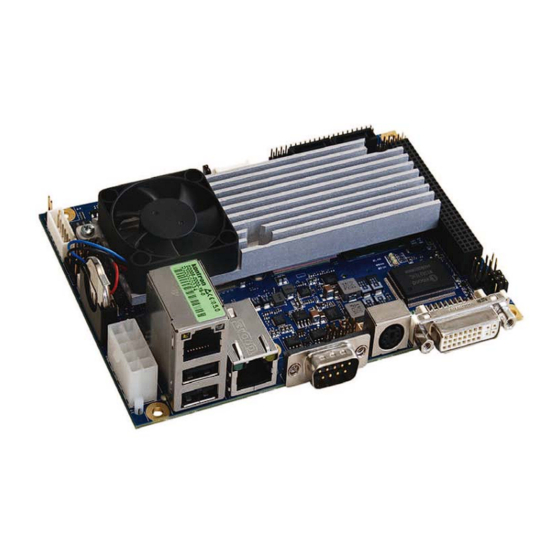
Introduction JRex Embedded Line Family Each JRex is a member of the 3.5" SBC family of KONTRON Technology A/S. JRex embedded line modules are characterized by the same surface pinouts and interfaces for reset logic and ATX power supply feature, 2 x USB, Fast LAN, PS/2 keyboard and mouse connector, Compact-Flash socket, CRT interface as well as one serial port. -
Page 9: Specifications
Serial Digital Video Out (SDVO) with DVI monitor interface (maximal 160 MHz pixel clock) Analogue Video Graphics Array output (VGA/CRT) up to WUXGA resolution (DVI-I connector) Onchip Parallel-ATA (P-ATA) Supports PIO mode, Multiword DMA and Ultra DMA up to UDMA5 Compact Flash (CF) socket useable as master or slave JRexplus-DC User's Guide... - Page 10 One parallel port configurable as enhanced parallel port (EPP) and extended capabilities One PS/2 keyboard and mouse controller Two serial ports (RS232) COM1 and COM2 First serial port optionally as RS-422 or RS-485 Fan controller Watchdog timer JRexplus-DC User's Guide...
- Page 11 Trusted Platform Module (LPC): Infineon SLB9635TT Chipset LPC bus supports TPM 1.2 devices Digital I/O (CPLD) Eight bidirectional I/O lines, +3.3V signal level ® BIOS: AMI , 1 MB Flash BIOS Real-Time Clock (RTC) with CMOS RAM and Battery JRexplus-DC User's Guide...
-
Page 12: Block Diagram
(KB + MS) SATA 0 SATA 0 Trusted Platform PC 104 Plus connector Module connector SATA 1 SATA 1 JRexplus-DC User's Guide... -
Page 13: Mechanical Specifications
CF card as boot device (default BIOS settings). The +12VDC line was not measured as this voltage is only used to supply backlights through the backlight connector J96. Article number 02008-0000-16-0 Supply voltage 5V DOS Prompt Soft Off S5 1,74 0,15 0,76 JRexplus-DC User's Guide... -
Page 14: Real-Time Clock Battery
Paristo voi räjähtää, jos se on virheellisesti samma batterityp eller en ekvivalent typ som asennettu. Vaihda paristo ainoastaan lalteval- rekommenderas av apparattillverkaren. Kassera mistajan suosittelemaan tyyppiln. Hävitä käytetty använt batteri enligt fabrikantens instruktion. paristo valmistajan ohjeiden mukaisesti. JRexplus-DC User's Guide... -
Page 15: Environmental Specifications
Figure 1 below shows MTBF de-rating for the E1 temperature range in an office or telecommunications environment. Other environmental stresses (extreme altitude, vibration, salt water exposure etc.) lower MTBF values. » System MTBF(hours) = 227228 @ 40°C JRexplus-DC User's Guide... -
Page 16: Getting Started
Getting started with the JRexplus-DC is very easy. Take the following steps: Connect the ATX-adapter (KAB-ATX-10) or the delivered 5V adapter (KAB-ADAPT-ATXto5V) to the JRexplus-DC 10pin ATX power connector J35. The location of connector J35 can be found in the Appendix B. -
Page 17: System Memory
A description of signals, including electrical characteristics and timings, is beyond the scope of this docu- ment. Please refer to the official PCI bus and PC/104-plus specifications for more details. Under no circumstances 5V PCI cards may be used on the JRexplus-DC board. Only Universal and 3.3V add- on cards are permitted. V is set to 3.3V on the PCI bus. -
Page 18: Graphics Interface
To protect the external power lines of peripheral devices make sure that - the wires have the right diameter to withstand the maximum available current. - to enclosure of the peripheral device fulfills the fire-protecting conditions of IEC/EN 60950. JRexplus-DC User's Guide... -
Page 19: Ddc Interpretation
The LVDS interface for the flat panel is available through the JILI30 connector (30 pins) J4 on the bottom side of the board. This connector represents the JILI interface. The implementation of this subsystem com- plies with the JILI specification of KONTRON Technology A/S. A variety of cables for different display types are available from KONTRON. -
Page 20: Jili30 Connector
- to enclosure of the peripheral device fulfills the fire-protecting conditions of IEC/EN 60950. Warning: Check jumper J2 (panel power) for correct settings for your panel – not doing so might cause permanent damage to your panel. JRexplus-DC User's Guide... -
Page 21: Panel Power
In this case the jumper setting (2-3) for 3.3V leads to a panel supply voltage of 12V. Note: All soldering works must be done in a professional production environment. To avoid loosing the guarantee for your product please contact the board vendor before you make any solder modification on the JRexplus-DC. JRexplus-DC User's Guide... -
Page 22: Connecting A Flat Panel
Graphics Interface Connecting a Flat Panel To determine whether your flat panel is supported check the KONTRON website for panel lists. We regularly update the list of panels that have been tested with the JRexplus-DC. If you use one of those adapters supplied by KONTRON configuration is easy: Check whether you have the correct adapter and cable for the panel you plan to use. -
Page 23: Extended Vesa Modes
To protect the external power lines of peripheral devices make sure that - the wires have the right diameter to withstand the maximum available current. - to enclosure of the peripheral device fulfills the fire-protecting conditions of IEC/EN 60950. JRexplus-DC User's Guide... -
Page 24: Jumper Settings
The jumper J5 can be used to set the backlight supply voltage to 5V or 12V. Pins Backlight Voltage 1 - 2 2 - 3 The jumper J3 can be used to invert the backlight-on signal of the backlight inverter. Pins Backlight-On High 1 - 2 2 - 3 JRexplus-DC User's Guide... -
Page 25: Serial Port Interfaces
N.C. Not connected Ground N.C. Receive data + / Not connected N.C. N.C. Not connected N.C. Receive data - / Not connected N.C. N.C. Not connected Attention: A RS-422/RS-485 terminating resistor is not equipped on the JRexplus-DC. JRexplus-DC User's Guide... - Page 26 To protect the external power lines of peripheral devices make sure that - the wires have the right diameter to withstand the maximum available current. - to enclosure of the peripheral device fulfills the fire-protecting conditions of IEC/EN 60950. JRexplus-DC User's Guide...
-
Page 27: Ps/2 Keyboard And Mouse Interface
PS/2 Keyboard and Mouse Interface The Super-I/O of the JRexplus-DC supports a PS/2 keyboard and mouse. A PS/2 keyboard can be directly connected to this interface. If you intend to use a PS/2 mouse connect a Y-cable to this interface. There are many different Y-cables available on the market. -
Page 28: Usb Interface
To protect the external power lines of peripheral devices make sure that - the wires have the right diameter to withstand the maximum available current. - to enclosure of the peripheral device fulfills the fire-protecting conditions of IEC/EN 60950. JRexplus-DC User's Guide... -
Page 29: Usb Limitations
KTD-S0008-F Page 24 USB Interface An USB interface cable is available from KONTRON (KAB-DUSB, part number 821401). 10.3 USB Limitations The power contacts for USB devices are protected. They are suitable to supply connected USB devices with a maximum current of 500 mA. Do not supply external USB devices with higher power consumption through these pins. -
Page 30: Eide Interface (P-Ata)
Alternatively the same interface can be used for Compact Flash card applications. Note: The connector of the JRexplus-DC was intended for the use with a cable link. When a KONTRON chip- disk or a CF card adapter is used the PCB's of these components point away from the board. -
Page 31: Compact Flash Card Interface
I/O write VCC3 Power +3.3V Interrupt VCC3 Power +3.3V N.C. Ground Not connected /RESET IOCHRDY Reset I/O channel ready /DRQ /DACK DMA request DMA acknowledge ATAD Drive activity UDMA detection Data 8 Data 9 Data 10 Ground JRexplus-DC User's Guide... -
Page 32: Jumper Setting
- the wires have the right diameter to withstand the maximum available current. - to enclosure of the peripheral device fulfills the fire-protecting conditions of IEC/EN 60950. Warning: Inserting or removing the Compact Flash card while in operation can cause serious damage and must be avoided. JRexplus-DC User's Guide... -
Page 33: Serial-Ata Interface (S-Ata)
Serial-ATA Interface (S-ATA) Serial-ATA Interface (S-ATA) The JRexplus-DC has two S-ATA ports. Serial-ATA connections boost the data rate theoretically up to 300 MB/sec. In addition it changes the parallel interface requiring 40 separate wires to a serial interface requi- ring only 6 wires. A RAID (Redundant Array of Independent Disks) configuration is not possible. -
Page 34: Lan Controllers
KTD-S0008-F Page 29 LAN Controllers LAN Controllers The JRexplus-DC supports a Fast LAN PCI and a Gigabit PCI Express LAN controller. 13.1 Gigabit LAN Controller ® The Gigabit LAN interface uses an Intel 82574L PCI Express LAN controller. The controller support 10/ 100/1000 Base-T interfaces. -
Page 35: Fast Lan Controller
The LAN interface is available through the RJ45 connector J20 (8 pins) that is combined with USB port 1/2. Header Signal Name Function TXD+ 10/100 transmit (positive) TXD- 10/100 transmit (negative) RXD+ 10/100 receive (positive) Ground Ground RXD- 10/100 receive (negative) Ground Ground JRexplus-DC User's Guide... -
Page 36: Pci Express Minicard
To protect the external power lines of peripheral devices make sure that - the wires have the right diameter to withstand the maximum available current. - to enclosure of the peripheral device fulfills the fire-protecting conditions of IEC/EN 60950. JRexplus-DC User's Guide... -
Page 37: Audio Interface
Audio Interface Audio Interface The JRexplus-DC supports a HD audio codec with 24 bit resolution and 192 kHz sample rate. The interface includes LINE OUT, LINE IN, MICROPHONE IN and a digital S/PDIF output. The HD audio controller is a bus mastering PCI device which is physically connected to one or more codecs via the HD Audio link. -
Page 38: Digital I/O Interface
Digital I/O Interface Digital I/O Interface The JRexplus-DC features eight bidirectional I/O lines. All I/O lines are TTL tolerant. Inputs can be driven from either +3.3V or +5V devices. This feature allows a mixed +3.3V / +5V system environment. 16.1... -
Page 39: Parallel Port Interface
KTD-S0008-F Page 34 Parallel Port Interface Parallel Port Interface The JRexplus-DC incorporates a parallel port that can be set to uni-/bidirectional and supports EPP/ECP operating modes. 17.1 Connector The parallel port is available through the connector X20 (32 pins). A DSUB25 adapter cable is deliverable from KONTRON (KAB-DSUB25-2, part number 61033). -
Page 40: Power Supply
KONTRON. For the ATX mode this is KAB-ATX-10 (part number 96072-0000-00-0). For the 5V only mode the adapter cable KAB-ADAPT-ATXto5V (P/N96072-0000-05-2) can be used. This cable is delivered with every JRexplus-DC. This cable allows to supply the board with 5V and 12V DC. Header... -
Page 41: Power Front Panel Header
Power button (positive) N.C. Not connected PWR_BTN- Power button (negative) PWR_LED- Power LED (negative) N.C. Not connected KBD_LOCK Keyboard lock RSVD Reserved Ground RSVD Reserved 17.3.1 Power LED The following picture illustrates the onboard wiring. 470R Power LED JRexplus-DC User's Guide... -
Page 42: Common Front Panel Pins
Not connected HDD_LED- Harddisk LED (negative) SPKR- Speaker (negative) The reset signal of the JRexplus-DC is edge-controlled. This means the board can not be hold within the reset. 18.1.1 Harddisk LED The following picture illustrates the onboard wiring. +3.3V Harddisk LED... -
Page 43: Crisis Management
Before saving your new settings with 'Save Changes and Exit' remove the jumper The board should be functional again now Autostart Function When the JRexplus-DC should start directly when the power is applied (without a power button signal) the autostart jumper J102 must be set. JRexplus-DC User's Guide... -
Page 44: Power And Thermal Management
To protect the external power lines of peripheral devices make sure that - the wires have the right diameter to withstand the maximum available current. - the enclosure of the peripheral device fulfills the fire-protecting conditions of IEC/EN 60950. JRexplus-DC User's Guide... -
Page 45: Setup Guide
Selection fields for current menu General Help Window Overlay (center) Help for selected menu Menu Bar The menu bar at the top of the window lists different menus. Use the left/right arrow keys to make a selec- tion. JRexplus-DC User's Guide... - Page 46 General Help Window Pressing <F1> or <Alt-F1> on a menu brings up the general help window that describes the legend keys and their alternates. Press <Esc> to exit the general help window. JRexplus-DC User's Guide...
-
Page 47: Menu Bar
22.4.1 Module Info Submenu Feature Option Description Board Name N / A Show the KONTRON specific board name Board Class N / A Show the KONTRON specific board class Serial Number N / A Show the KONTRON specific serial number... -
Page 48: Advanced Menu
Enable or disable power saving modes (a C-STATE is an idle state). C0 is the operational state, C1 to C4 represents the Enabled saving modes Enhanced C-States Disabled Enable or disable the enhanced power saving modes (C1E to C4E) Enabled JRexplus-DC User's Guide... -
Page 49: Onboard Device Configuration Submenu
Throttling Enabled DT in SPD Disabled Support the Delta Temperature in the DRAM SPD thermal management algorithm Enabled TS on DIMM Disabled Support the Thermal Sensor on DIMM thermal management functionality Enabled JRexplus-DC User's Guide... -
Page 50: South Bridge Submenu
PCIE Port 0 Auto Enable or disable PCI Express ports and the associated devi- Enabled PCIE Port 1 Disabled PCIE Port 0 IOxAPIC Disabled Enable or disable the I/O APIC feature Enable Enabled PCIE Port 1 IOxAPIC Enable JRexplus-DC User's Guide... -
Page 51: Ide Configuration Submenu
IDE Detect Time Out (Sec) 0, 5, 10, 15 Select the time out value for the detection of ATA(PI) devices 20, 25, 30, 35 ATA(PI) 80Pin Cable Host&Device Select the mechanism for detecting 80 pin cable Detection Host Device JRexplus-DC User's Guide... -
Page 52: Primary/Secondary/Third Master/Slave Submenu
MWDMA0 - 2, UDMA0 - 6 S.M.A.R.T. Auto Show if the device is capable of using the error prede- diction tool Disabled Enabled 32Bit Data Transfer Disabled Enable 32 bit communication between CPU and IDE controller Enabled JRexplus-DC User's Guide... -
Page 53: Ethernet Configuration Submenu
A dummy FDD device is created that will be associated with a hot-plugged FDD later. 'Auto' creates this device only if Enabled there is no USB FDD present Auto 8 USB Mass Storage Submenu Display the status of USB mass storage devices Device Configuration JRexplus-DC User's Guide... -
Page 54: Usb Mass Storage Device Configuration Submenu
DMA0, DMA1 Select the DMA channel for ECP specification DMA3 PS/2 Mouse Support Disabled Enabled forces the mouse port to be enabled regardless if a mouse is present. 'Auto' frees IRQ12 if no mouse is present. Enabled Auto JRexplus-DC User's Guide... -
Page 55: Trusted Computing Submenu
Auto Use PAID (Panel Adapter ID) or FPID (Flat Panel ID) to manually enter a panel record (KONTRON specific). If Auto Fixed Mode the board is searching for a JILI3 (KONTRON), EDID (VESA) PAID or a DisplayID (VESA) record FPID... -
Page 56: Acpi Configuration Submenu
S1 (POS) Define the power down mode S3 (STR) POS = Power On Standby STR = Suspend To RAM Auto Determine whether to invoke the VGA BIOS post on suspend Repost Video on S3 event (resume) Resume JRexplus-DC User's Guide... -
Page 57: Advanced Acpi Configuration Submenu
Enables a set of timers (3 timer) that can be used by the ope- rating system. Each timer can be configured to cause a sepa- Timer Enabled rate interrupt HPET Memory Address FED00000h Define HPET (High Precision Event Timer) memory address FED01000h FED02000h FED03000h JRexplus-DC User's Guide... -
Page 58: Acpi Cooling Options Submenu
Show hardware health information Configuration 8 Watchdog Submenu Configure the watchdog feature Configuration 8 MPS Configuration Submenu Configure the Multi Processor table Submenu Configure the System Management BIOS 8 SMBIOS Configuration 8 Remote Access Submenu Configure remote access Configuration JRexplus-DC User's Guide... -
Page 59: Hardware Health Configuration Submenu
1s, 5s, 10s, 30s 1:00m, 5:30m 10:30m, 30:30m Select maximum trigger period Trigger Timeout Disabled 1s, 5s, 10s, 30s 1:00m, 5:30m 10:30m, 30:30m 22.5.5.3 MPS Configuration Submenu Feature Option Description MPS Revision Select MPS (Multi Processor Specification) revision JRexplus-DC User's Guide... -
Page 60: Smbios Configuration Submenu
ESC-sequences to VT100 VT100 VT-UTF8 VT-UTF8 Combo Key Disabled Support for ANSI/VT100 terminals Support Enabled Sredir Memory Display No Delay Gives the delay to display memory information Delay Delay 1 Sec Delay 2 Sec Delay 4 Sec JRexplus-DC User's Guide... -
Page 61: Pcipnp Menu
DMA Channel 7 Reserved Memory Size Disabled Memory size to reserve for legacy ISA devices 16k, 32k, 64k Reserved Memory Address C0000, C4000 Base address of memory to reserve for legacy ISA devices C8000, ... D8000, DC000 JRexplus-DC User's Guide... -
Page 62: Boot Menu
Setup after memory initialization otherwise this messa- Display Enabled ge is suppressed Interrupt 19h Capture Disabled If enabled 'Addon ROMs' can be trapped interrupt 19h (boot IRQ) Enabled Flash Write Protection Disabled Write-protect the BIOS flash chip Enabled JRexplus-DC User's Guide... -
Page 63: Security Menu
Cancel CMOS you can restore the values you saved to CMOS Load Optimal Defaults Load the optimal default values Cancel Load Failsafe Defaults Load the failsafe default values Cancel JRexplus-DC User's Guide... -
Page 64: Appendix A: System Resources
Note (1) Real Time Clock (RTC) ACPI Power Management PCI IRQ for PCI Dynamic PCI IRQ for PCI Dynamic PS/2 Mouse Note (1) Floating Point Unit (FPU) IDE Controller (Primary) Note (1) Note (1) IDE Controller (Secondary) JRexplus-DC User's Guide... - Page 65 PCI IRQ for PCI PCI IRQ for PCI PCI IRQ for PCI PCI IRQ for PCI PCI IRQ for PCI Note: If the Used for device is disabled in the BIOS Setup the corresponding interrupt is free. JRexplus-DC User's Guide...
-
Page 66: Direct Memory Access (Dma) Channels
1 MB (high memory, extended memory) is accessed under DOS via special drivers such as HIMEM.SYS. ® Other operating systems (Linux or Windows versions) allow you to address the full memory area directly. Memory Range Used for Available Comment C0000h - CFFFFh VGA BIOS D0000h - DFFFFh E0000h - FFFFFh System BIOS JRexplus-DC User's Guide... -
Page 67: I/O Address Map
Appendix A: System Resources I/O Address Map The I/O-port addresses of the JRexplus-DC are functionally identical to a standard PC/AT. All addresses not mentioned in this table should be available. We recommend that you do not use I/O addresses below 0100h with additional hardware for compatibility reasons even though they are available. -
Page 68: Pci Devices
INTA Onboard PCI Express device System Management Bus (SMBus) The JRexplus-DC uses an onboard System Management Bus (SMBus). This bus is not available on a peri- pheral connector and therefore cannot be used for external SMBus devices. SMBus Address Device... -
Page 69: Appendix B: Connector Layout
KTD-S0008-F Page 64 Appendix B: Connector Layout Appendix B: Connector Layout Connector Locations B.1.1 Top Side JRexplus-DC User's Guide... -
Page 70: Bottom Side
KTD-S0008-F Page 65 Appendix B: Connector Layout B.1.2 Bottom Side JRexplus-DC User's Guide... -
Page 71: Mechanical Dimensions
KTD-S0008-F Page 66 Appendix B: Connector Layout Mechanical Dimensions 101.6 98.3 94.9 78.9 14.9 JRexplus-DC User's Guide... -
Page 72: Mating Connectors
(JST SXH-002T-P0.6 or comp.) and Microphone) 1.25 mm 3 pin fan interface (MOLEX 51021-0300 or comp.) 1.25 mm 10 pin for DSUB9 adaption (COMB) (MOLEX 51021-1000 or comp.) 1.25 mm 7 pin for backlight connector (MOLEX 51021-0700 or comp.) JRexplus-DC User's Guide... -
Page 73: Pinout Tables
AD24 C/BE3 IDSEL3 (AD23) AD26 AD25 AD29 VCC5 AD28 AD27 VCC5 AD30 AD31 REQ0 REQ1 REQ2 VCC5 GNT0 GNT1 GNT2 VCC5 CLK0 CLK1 CLK2 VCC5 CLK3 INTD VCC5 VCC12 (+12V) INTA INTB INTC VCC12# (-12V) REQ3 GNT3 JRexplus-DC User's Guide... - Page 74 /DACK PANEL_VCC SMB_CLK PANEL_VCC PETn0 N.C. /CS3 SMB_DATA PETp0 ATAD /IOR /IOW VCC3 USB- /CS1 /CS3 VCC3 USB+ VCC3 N.C. VCC5 /RESET VCC3 VCC5 IOCHRDY /LED_WWAN N.C. /DACK /LED_WLAN N.C. ATAD /LED_WPAN N.C. VCC1 N.C. N.C. VCC3 JRexplus-DC User's Guide...
- Page 75 To protect the external power lines of peripheral devices make sure that - the wires have the right diameter to withstand the maximum available current. - to enclosure of the peripheral device fulfills the fire-protecting conditions of IEC/EN 60950. JRexplus-DC User's Guide...
-
Page 76: Appendix C: Reference Documents
KTD-S0008-F Page 71 Appendix C: Reference Documents Appendix C: Reference Documents KONTRON Technology A/S can't guarantee the availability of internet addresses. Document Internet Address Advanced Configuration and Power Interface (ACPI) http://www.acpi.info/spec.htm AT Attachment Storage Interface Specification (ATA) http://t13.org Digital Visual Interface (DVI) http://www.ddwg.org... -
Page 77: Appendix D: Document Revision History
07/19/11 Added MTBF information S0008-1 06/24/11 Updated for redesigned hardware with 5V only mode and crisis management S0008-0 02/03/10 Adapted to KONTRON Technology A/S guidelines 06/10/09 Initial release Corporate Offices North America Asia Pacific Europe, Middle East & Africa 17 Building,Block #1,ABP 14118 Stowe Drive Oskar-von-Miller-Str.
Need help?
Do you have a question about the JRexplus-DC and is the answer not in the manual?
Questions and answers