
Related Manuals for Physipro NeoX


Summary of Contents for Physipro NeoX
- Page 1 Owners Manual This manual contains important information about this product. Please pass it to the final user upon delivery.
-
Page 2: Table Of Contents
NEOX™ Tilt-in-Space ENGLISH Physipro Inc. is delighted to have you as one of our clients. We sincerely wish to thank you for the trust you have shown in our company by choosing one of our products. This user manual has been designed to allow you, the client, to use the NEOX™... - Page 3 13.7 To apply Attendant Wheel Lock 6 wheel option............43 14. Anti-tip tubes..........................44 14.1 Adjustment..........................44 14.2 Installation..........................44 14.3 Remove............................45 15. Transit use............................46 Maintenance..........................47 Warranty............................49 Annexe A NEOX Standard — Settings and Restrictions ..........50 Annexe B Settings and restrictions — NEOX HQC............56 Revision 5 January 2016...
-
Page 4: Neox™ Parts
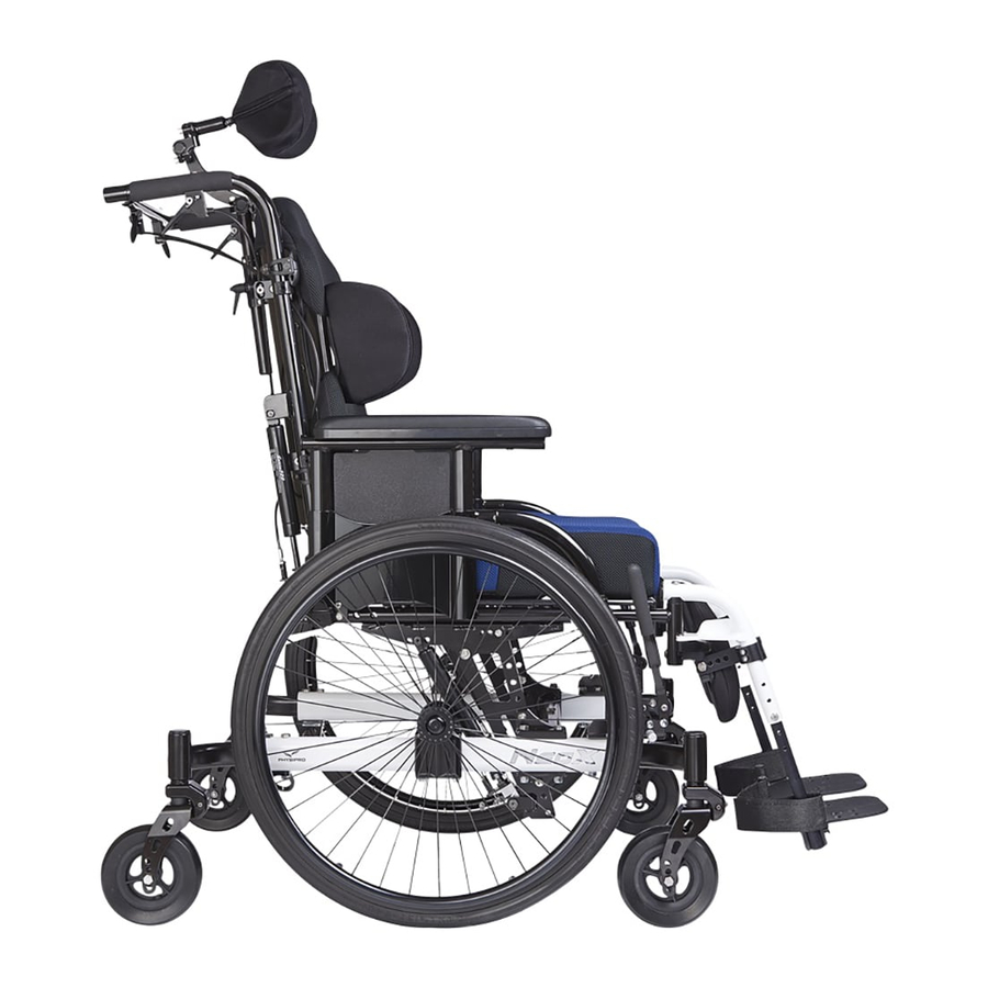
The main components are provided with the standard model. Several options and accessories are also available. Please contact us for more details or refer to the purchase order. Armrest Transit use Legrest Rear wheel mechanism Wheel lock Footplate Front wheel Figure 1 : Main Base Components of the NEOX Standard... -
Page 5: Specifications
+8" to +12" based on option chosen Rear wheel diameter 12", 16", 20", 22", 24" Front wheel diameter 5", 6", 8" Neox 4 wheels: 50.8 lb Neox 6 wheels: 55.8 lb Transport weight* Neox HQC : 54 lb (24.5kg) Maximum load 250 lb / 350 lb Back angle 85°... -
Page 6: Safety And Maintenance
Wheel Locks Lock Extension, Retractable Wheel lock extension Transit option Physipro Inc. offers several accessories and options to help you customize your wheelchair according to your specific needs. Please contact us for more details or refer to the purchase order. -
Page 7: Safety
Owners manual ENGLISH 3.2 Safety Several safety measures must be applied to ensure the safety of the user and the individuals who handle or use the wheelchair. Note that the following list is not exhaustive. Therefore, the user and the individuals who handle or use the wheelchair have the responsibility to handle it or use it cautiously. - Page 8 NEOX™ Tilt-in-Space ENGLISH Going up and down stairs The intervention of two assistants is required to go up or down stairs. To do so, one assistant should stand behind the wheelchair holding the push handles. The second assistant should maintain...
-
Page 9: Weight Limitation
Always wear your seat positioning strap. The seat positioning strap is an option on this chair. You may order without the seat positioning strap. To ensure an additional safeguard, Physipro strongly recommends ordering the seat positioning strap. However, the seat positioning strap as a primary purpose of positioning. -
Page 10: Cleaning, Storage And Recommendations
NEOX™ Tilt-in-Space ENGLISH WARNING The anti-tippers are not to be used as tipping levers. Tires Ensure your wheelchair has the proper tire pressure before using it. Proper pressure extends the life of your tires and facilitates its use. The recommended tire pressure is listed on the tire. -
Page 11: Depth And Width Adjustments
4. Depth and Width adjustments 4.1 Seat depth modification The NEOX™ seat depth can be modified by moving the backrest canes. All seat depths ordered allow for an increase or decrease of the depth by 1". Please note that a 14" seat depth only increases by 2" and a seat 22" only decreases by 2". -
Page 12: Seat Width Modification
NEOX™ Tilt-in-Space ENGLISH 4.2 Seat width modification The seat width can be modified by adjusting the crossbars. Three types of configurations are possible; small frame 14" to 19", extended frame 19" to 22" and HD frame 20" to 26". Follow these steps to modify the width: 1. -
Page 13: Seat To Floor Height
5. Seat to floor height Please note that the minimum seat to floor height of the NEOX™ can vary depending on the rear wheel and front wheel diameter combination. The other heights available can be obtained by adjusting the frame. - Page 14 NEOX™ Tilt-in-Space ENGLISH Self propelling configuration (Standard Neox Only) 6 Wheel configurations Required Location Mid-Wheel Drive Seat-to-Floor height 20" 14" to 19" 22" 14" to 19" 24" 15" to 20" Please note that the central wheels are the only wheels that have to be chosen in function of the seat-to-floor height.
-
Page 15: Rear Wheels
Insert nut C at the end of the axle A; Tighten nut C with a ¾" wrench while holding the axle A with a ¾" ratchet. Note – To simplify this process; place the NEOX™ on a flat surface such as a table or a bench. - Page 16 NEOX™ Tilt-in-Space ENGLISH 6.3 Installing Rear Wheels - Permanent Wheel Axle Make sure the positioning device E is inserted in block F; Secure it firmly in place with the lock washer D and nut C; Insert axle A in the positioning device E with the wheel hub B;...
-
Page 17: Horizontal Adjustment
Owners manual ENGLISH 6.4 Installing Rear Wheels - Quick-Release Axle Make sure the positioning device E is inserted in block F; Secure it firmly in place with the lock washer D and nut C; Insert axle A in the positioning device E with the wheel hub B. Figure 14 : Rear Wheel Installation 6.5 Adjusting Quick Release Axle Tighten or loosen nut C with a 3/4"... -
Page 18: Quick Release Axle
4. Replace screw A and B, tighten. Always use the more stable position (Wheel Backward) to guaranty stability. To propel, consider the 6 wheel configuration. Please refer to Appendix B for wheel position restrictions for the NEOX HQC. -
Page 19: Rear Wheel Lateral Adjustment
Owners manual ENGLISH 6.8 Rear Wheel Lateral Adjustment This modification is used to move the rear wheels closer or further from the frame. To do so, follow these instructions: Remove the rear wheel (refer to section 6.2 ; 6.3); Untighten nut A to release the positioning device B with the use of a 1 ”... - Page 20 NEOX™ Tilt-in-Space ENGLISH Fold in the adjustable strap on itself. Move the clamping ring on the overlap adjustable strap. Figure 21 Tighten the screw using a 3mm Allen Key. Figure 22...
-
Page 21: Clearing Obstacles - Tilt Rear Wheel Mechanism (6-Wheel Configuration)21
Owners manual ENGLISH 6.10 Clearing obstacles – Tilt Rear Wheel Mechanism (6-wheel configuration) 1. For security reasons, it is important to HAVE THE UPHOLSTERY PARALLEL TO THE GROUND and to REMOVE THE PATIENT’S WEIGHT FROM THE BACK WHEELS before using the mechanism. 2. -
Page 22: Front Wheels
NEOX™ Tilt-in-Space ENGLISH 7. Front Wheels 7.1 Front wheels installation To change the wheels, simply follow these instructions: Determine the front wheel position on the fork. Refer to section 5. Insert screw A in the corresponding hole with both spacers B between the wheel and fork on each side. -
Page 23: Caster Installation
Ensure tightness when the forks are installed. Verify that the fork rotates properly. Otherwise, loosen nut slightly. Any change to the Neox™ must be performed by a professional. Non- compliance with this notice may result in severe consequences for the safety of the users and individuals in contact with the base. -
Page 24: Back
NEOX™ Tilt-in-Space ENGLISH 8. Back 8.1 Back angle modification The NEOX™ back angle can be adjusted to satisfy your client’s needs. To do so, follow these instructions: Unscrew screw A with a 10 mm and a 4 mm Allen key. -
Page 25: Dynamic Back
Owners manual ENGLISH 8.2 Dynamic Backrest Installation Follow these instructions to replace a standard back width a dynamic back: Remove the armrests and the wheels; Remove the backrest ; Unscrew bolt A to remove the back posts; Figure 29: Dynamic Backrest Installation Remove the armrest hardware B, screw C and screw H on the small tube;... -
Page 26: Back Cane Height Adjustment
NEOX™ Tilt-in-Space ENGLISH Install the bottom part of the dynamic back post by re-inserting the two sleeves E; Re-install bolts J and armrest hardware; Re-install back post and backrest; 10. Replace armrest and rear wheels. Figure 32 : Dynamic Backrest Installation Figure 31 : Dynamic Backrest Installation 8.3 Back posts height modification... -
Page 27: Recliner Backrest
Owners manual ENGLISH 8.4 Recliner backrest To recline the back, simultaneously press handles A, located on the reclining back bar, and set the back angle. Release both handle A to lock. Tension Bar Reclining Back for headrest support Reclining backpost Figure 34 : Recliner Backrest Figure 35 : Recliner Backrest Revision 5... - Page 28 NEOX™ Tilt-in-Space ENGLISH Determine the position of the backpost J depending on the desired seat depth. Figure 36 : Recliner Backrest Insert bushing G, H and I inside the holes of plates F and K. Figure 37 : Recliner Backrest Complete assembly with hardware Repeat these steps for the right backpost.
-
Page 29: Reclining Back Bar
Owners manual ENGLISH 8.5 Reclining back bar Insert the adjustable bar of the reclining back O in the tube P. Using a 4 mm Allen Key, tighten screw Q. Figure 39 : Reclining back bar 8.6 Tension bar for headrest support Insert R in tube S. - Page 30 NEOX™ Tilt-in-Space ENGLISH Installation of the reclining back bar 1. Using a 4 mm Allen Key tighten screws U. Installation of the tension bar for headrest support 2. Using a 4 mm Allen Key tighten screws V. Recline handles installation 3.
-
Page 31: Installation - Angle Adjustable Pushhandle (Optional)
Owners manual ENGLISH 8.7 Installation - Angle adjustable pushhandle (optional) To install the pushhandle please follow these instructions: 1. Remove the original coating (if applicable); 2. Insert the tube into the back tube receiver and screw bolt A using a 3 mm Allen key;... -
Page 32: Tilt-In-Space
ENGLISH 9. Tilt-in-Space 9.1 Positive Tilt The Neox™ can be tilted backward, in a positive tilt, please follow these steps to do so: Activate the wheel lock B before positioning the Neox™ in a positive tilt. (Figure 21). Refer to section 14.3;... -
Page 33: Negative Tilt
By default, the upright position is 0°. To obtain a negative tilt, move the adjustment block D and the gas cylinder G forward (figure 48-b). Position the NEOX™ in a positive tilt and then unscrew bolts E and F using a 4 mm Allen key and a 10 mm wrench. -
Page 34: Armrests
NEOX™ Tilt-in-Space ENGLISH 10. Armrests 10.1 Armrests Type «U» 11.1.1 Flipping Armrest Back Depress the release latch A Pull the armrest toward back of wheelchair 11.1.2 Armrest Height Adjustment Push the release latch B; Figure 48 :Type “U in Armrest Slide arm pad C up or down to the desired height;... - Page 35 Owners manual ENGLISH 10.2.3 Height Adjustment Unscrew screw E and nut D; Slide the armrest up or down to desired height; Reinsert screw E and tighten nut D. Figure 50 10.2.4 Side-Guard Height Adjustment Unscrew screw F; Slide the side guard G up or down to desired height; Tighten screw F firmly in place.
- Page 36 NEOX™ Tilt-in-Space ENGLISH 10.2.5 Depth Adjustment Unscrew screw I and nut H to remove the receiver C of the armrest; Place receiver C to desired position; Reinsert screw I and nut H; Tighten firmly in place; Repeat opposite side. Figure 52 NOTE: All adjustments can be perform with a 5 mm Allen key and a 10 mm Wrench.
-
Page 37: Footrest
Owners manual ENGLISH 11. Footrests 11.1 Swing-in/swing-out footrests Place the footrest into the receiver on front frame tube with the footrest facing outward from the frame; Rotate the footrest inward until it locks into place on locking bolt; To swing-out, press handle A to unlock the footrest and rotate outward. -
Page 38: Folding Footplate
NEOX™ Tilt-in-Space ENGLISH 11.5 Footplate Vertical Adjustment To fold, simply pivot footplate upward to vertical position. To adjust the footplate according to angle ß (Figure 31), slightly unscrew screw E using ¼" Allen Key. Please note that the Allen key must be inserted opposite side of the adjustment block. -
Page 39: Height Adjustment
Owners manual ENGLISH 12.2 Height adjustment Remove screw B using a 10 mm wrench; Slide footrest extension up or down inside the frame tube to the desired height; Replace screw A, tighten. Figure 58: Articulated Legrest Height Adjustment 12.3 Angle adjustment To raise legrest, hold the lower part of the footrest while pulling it up ;... -
Page 40: Wheel Lock
NEOX™ Tilt-in-Space ENGLISH 13. Wheel lock 13.1 Wheel lock installation The wheel size will determine the location of the mid-wheels lock. The installation of the wheel lock must be made when the rear wheels are installed. Refer to section 7.1 to install the mid-wheels. -
Page 41: Attendant Wheel Lock - 4 Wheel Option
Owners manual ENGLISH Never stop a moving wheelchair with wheel locks. Wheel locks are not brakes. When breaks are applied, the breaking stop must sink into the tire by ” to ¼". It is important to adjust the brakes if modifications of the rear wheels are done or if the tires are worn out. -
Page 42: To Apply Attendant Wheel Lock 4 Wheel Option
NEOX™ Tilt-in-Space ENGLISH 13.5 To Apply Attendant Wheel Lock 4 wheel option Push the footplate on the side J to apply the brakes. Push the handle on the side K to release the brakes. Figure 64: Apply brakes 4 wheels 13.6 Attendant Wheel Lock 6 wheel option... -
Page 43: To Apply Attendant Wheel Lock 6 Wheel Option
Owners manual ENGLISH Position and adjust the foot operated brake F on the frame structure E by tightening bolts G and nuts H with transit I. Note: Ensure that the wheel lock rods are located at ½" of the wheel when the wheel lock is not applied. -
Page 44: Anti-Tip Tubes
Always verify if the anti-tippers are at proper height after making any adjustment or modification to the wheelchair in order to ensure the safety of the user. Physipro recommends anti-tippers for all wheelchairs. The anti-tippers are not to be used as tipping levers. -
Page 45: Remove
Owners manual ENGLISH 14.3 Turning the anti-tippers Turn anti-tippers inwards towards the frame when being pushed by an attendant or overcoming obstacles such as climbing curbs. 1. Press the rear anti-tipper release pin A on the anti-tipper tube so that both release pins are drawn inside. -
Page 46: Transit Use
The anchorage rings of the wheelchair do not substitute for the restraining system certified by Transport Canada. PHYSIPRO is not responsible for the risks undertaken when using the wheelchair as a seat in public or private transportation. Failure to follow these warnings may cause damage to your chair, a fall,... -
Page 47: Maintenance Guide
ENGLISH 16. Maintenance Guide Maintenance is an essential part of keeping the NEOX™ Tilt-in-Space in good working order. By doing so, you will maximize its operational life and ensure it is always safe to use. Do not forget to have a qualified professional inspect your wheelchair twice a year. - Page 48 NEOX™ Tilt-in-Space ENGLISH Every At Time of Each Each Checklist Receipt Week Month Months Tilt-in-Space cylinder backrest § Verify the effectiveness of the handle and the cylinder § Verify that there are no oil leaks Armrests § Check if armrests are secured properly and still comfortable.
-
Page 49: Warranty
Tires, inner tubes, comfort upholsteries, armrests, seat covers, backrest covers and ball bearings. Physipro inc. agrees to repair or replace any inoperative or defective part for the duration of the warranty period. To enjoy this warranty service, please contact Physipro Inc. or an authorized dealer. -
Page 50: Annexe A Neox Standard - Settings And Restrictions
NEOX™ Tilt-in-Space ENGLISH Appendix A : NEOX Standard — Settings and Restrictions This document appendix describe the range of adjustment available and limits on the NEOX tilt in space. It covers the following sections: • Adjustment sequence • Seat depth adjustment • Center of mass adjustment • Gas cylinder adjustment... - Page 51 Owners manual ENGLISH Table 1: Back position and hanger position versus seat depth SEAT DEPTH STANDARD SEAT DEPTH EXTENDED BACKREST POSITION HOOK POSITION FRAME (INCHES) FRAME (INCHES) Center of mass adjustment The adjustment of the center of mass is really important.
- Page 52 Figure 3: Gas cylinder adjustment tilting from 3 to 44 degrees. Seat to floor height adjustment / limitations The NEOX seat to floor height may be adjusted. The overall range is from 13 inches to 20 inches including all wheel configuration. With a specific wheel configuration, the range of adjustment is 5 inches (as shown in Figure 4).
- Page 53 Figure 5 shows the rearward stability test. The table is given as reference only, results could be influence by the anthropometry of the patient. Figure 5: Rearward stability test with a reclining backrest on the NEOX tilt in space. Table 4: Maximum tilt/recline for 10 degree minimum stability in least stable configuration.
- Page 54 The overall width of the Neox without pushrim is establish by the following Overall width=seat width+9.5 inches For larger seat width, this overall width may not be acceptable. That’s why the Neox has optional extension plates that can be installed between the seat frame and the tilting mechanism. The purpose of the plates is to have the wheels underneath the armrest (compare to outside, see Figure 6 and Figure 7) to minimise the overall width and get a better pushing efficiency.
- Page 55 Owners manual ENGLISH Table 5, Overall width for different configuration OVERALL WIDTH (INCHES) SEAT Standard with Standard with extension plates Standard Standard with pushrim WIDTH extension plates (+7.5) and pushrim (+9) (+9.5) (+11) (INCHES) N.A.* N.A.* 23.5 N.A.* N.A.* 24.5 23.5 25.5 24.5...
-
Page 56: Hqc
Armrest Height 10" Armrest Height 12" 14.5 19.5 33.5 Appendix B: Settings and restrictions — NEOX HQC The instructions below must be followed for proper adjustment of the NEOX HQC Tilt-in- Space: • Adjust the seat width according to the order form. • Adjust the seat depth according to the order form and reference table. • Adjust the NEOX according to the user’s weight (cylinder position and wheels), according to the reference table. - Page 57 Adjustment according to user’s weight The gas cylinders can be positioned according to the user’s weight, in order to minimize the effort needed to obtain the desired position when the user is in the NEOX. Three configurations are available as shown in figure 2.
- Page 58 NEOX™ Tilt-in-Space ENGLISH To adjust the position of the gas cylinders, loosen bolt A using a 10-mm Allen key. Remove bolts B using a 5-mm Allen key. Place the gas cylinder in the desired position. Ensure that the threaded block C is in an upright position with the threads aligned with the holes in plate D. Put back bolts B.
- Page 59 ENGLISH Seat-to-floor height—Settings and restrictions The seat-to-floor height ajustment range of the NEOX is between 13” to 20” over all the wheel configurations. For any specific wheel configuration, the adjustment range is 5’’ (as shown in the figure below). Depending on the floor/seat adjustment, maximum inclination may vary due to mechanical interference.
- Page 60 Seating and Mobility Solutions Canada Europe 370, 10e Avenue Sud Village des entrepreneurs Sherbrooke (Québec) J1G 2R7 461, rue Saint-Léonard Canada 49000 Angers France 1 800 668-2252 info@physipro.com 02 41 69 38 01 www.physipro.com contact@physipro.fr...
Need help?
Do you have a question about the NeoX and is the answer not in the manual?
Questions and answers