Symbol PDT 7200 series Reference Manual
Windows ce 3.0
Hide thumbs
Also See for PDT 7200 series:
- Product reference manual (155 pages) ,
- Product reference manual (139 pages) ,
- Quick reference manual (28 pages)
Table of Contents
Advertisement
Quick Links
Download this manual
See also:
Quick Reference Manual
Advertisement
Table of Contents

Related Manuals for Symbol PDT 7200 series


Summary of Contents for Symbol PDT 7200 series
- Page 1 PDT 7200 Series Product Reference Guide for Windows CE 3.0...
- Page 2 PDT 7200 Series Product Reference Guide for Windows CE 3.0 72-57170-01 Revision A — March 2002 Symbol Technologies, Inc. One Symbol Plaza, Holtsville N.Y. 11742-1300...
- Page 3 PDT 7200 Series ® Product Reference Guide for Windows CE 3.0 72-57170-01 Revision A March 2002...
- Page 4 The software is provided strictly on an “as is” basis. All software, including firmware, furnished to the user is on a licensed basis. Symbol grants to the user a non-transferable and non-exclusive license to use each software or firmware program delivered hereunder (licensed program).
-
Page 5: Table Of Contents
Symbol Support Centers ........ - Page 6 Symbol Windows® CE SDK ........
- Page 7 Contents Using the Touchscreen ............5-5 Using the Touchscreen Keypad .
- Page 8 Symbol Test Applications ........
- Page 9 Contents Out To Launch ............B-23 Calculator .
- Page 10 ® PDT 7200 Series Product Reference Guide for Windows viii...
-
Page 11: About This Guide
The PDT 7200 Series Product Reference Guide for Windows CE provides general instructions for the System Administrator for setting up, initializing, operating, troubleshooting, and maintaining the PDT 7200 Series Windows CE terminal. Chapter Descriptions Chapter 1, Getting Started, describes the procedures for setting up the terminal. -
Page 12: Notational Conventions
" to identify chapters and sections in this and related documents. Square brackets [] in a command line enclose optional inline parameters. The piping symbol | has the effect of “or” when it is used to separate inline parameters on a command line; i.e., it separates alternative values for parameters. -
Page 13: Related Publications
70-12057-XX Service Information If you have a problem with the PDT 7200 equipment, contact the Symbol Support Center. If your problem cannot be resolved over the phone, you may need to return your equipment for servicing. If that is necessary, you will be given special directions. - Page 14 ® PDT 7200 Series Product Reference Guide for Windows United Kingdom Asia/Pacific Symbol Technologies Symbol Technologies Asia, Inc. Symbol Place 230 Victoria Street #04-05 Winnersh Triangle, Berkshire RG41 5TP Bugis Junction Office Tower United Kingdom Singapore 188024 0800 328 2424 (Inside UK)
- Page 15 Symbol Technologies Norway Postbus 24 7050 AA Hoybratenveien 35 C Varsseveld, Netherlands N-1055 OSLO, Norway 315-271700 (Inside Netherlands) Symbol’s repair depot and shipping address: +31-315-271700 (Outside Netherlands) Symbol Technologies Norway Enebakkveien 123 N-0680 OSLO, Norway +47 2232 4375 South Africa Spain/España...
-
Page 16: Warranty
This warranty is provided to the original owner only and is not transferable to any third party. It shall not apply to any product (i) which has been repaired or altered unless done or approved by Symbol, (ii) which has not been maintained in accordance with any operating or handling instructions supplied by... -
Page 17: Warranty Coverage And Procedure
Shipments from the US or other locations will be made F.O.B. Symbol’s manufacturing plant. Symbol will use new or refurbished parts at its discretion and will own all parts removed from repaired products. Customer will pay for the replacement product in case it does not return the replaced product to Symbol within 3 days of receipt of the replacement product. - Page 18 ® PDT 7200 Series Product Reference Guide for Windows...
-
Page 19: Chapter Contents
Chapter 1 Getting Started Chapter Contents Introduction ............1-3 Unpacking the Terminal . - Page 20 ® PDT 7200 Series Product Reference Guide for Windows...
-
Page 21: Introduction
Carefully remove all protective material from around the terminal and save the shipping container for later storage and shipping. Verify that you received all equipment listed on the packing slip and inspect the equipment for damage. If you find any damaged or missing items, contact the Symbol Support Center immediately. -
Page 22: Parts Of The Terminal
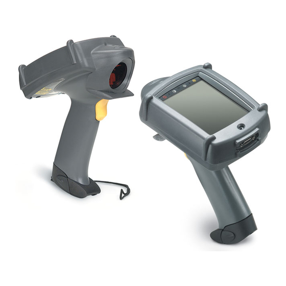
® PDT 7200 Series Product Reference Guide for Windows Parts of the Terminal The following illustration displays the basic parts of the PDT 7200 terminal. A brief description of each part follows. Status LEDs Control Panel Speaker 1/4 VGA sized Display... -
Page 23: Accessories/Peripherals
A/C power storage. Symbol offers a single-slot cradle containing an RS-232C communication port. Each cradle is supplied with (and requires) its own international power supply with IEC connector. The cradle provides terminal storage, in-terminal battery charging, spare battery pack charging, and RS-232 communications to a host computer or an external serial device such as a printer. -
Page 24: Sdk
If the terminal does not power on, perform a hard reset. See Booting the Terminal page 5-3 for instructions. As the terminal initializes its unique Flash File system, the Symbol splash screen displays for about a minute. -
Page 25: Calibrating The Screen
Tap the center of the target with the stylus. Repeat as the target moves around the screen. Figure 1-1. Tapping Target ® 2. Tap the screen to continue booting Windows 3. The Symbol Shell and Launcher programs are deployed. - Page 26 ® PDT 7200 Series Product Reference Guide for Windows...
-
Page 27: Chapter Contents
Symbol Windows® CE SDK........ - Page 28 ® PDT 7200 Series Product Reference Guide for Windows...
-
Page 29: Introduction
Software Installation on the Development PC Introduction To develop applications to run on the PDT 7200, the Symbol Technologies, Inc. Windows® CE Software Developer’s Kit for Symbol Terminals (SDK) is available. This SDK contains ® PDT 7200-specific software not available in the standard Microsoft Windows CE SDK. -
Page 30: Before You Install The Sdk
HTML Help files. Installing the SDK on the Development PC ® The Windows CE SDK installs through Windows in the directory C:\SYMBOL WINDOWS ® CE SDK, and also installs files in the Windows CE Tools directory (generated by the CE Tool Kit). - Page 31 Software Installation on the Development PC Note: To ensure the best operation of the SDK, do not change the base path set up in the installation. 4. Follow the installation prompts.
- Page 32 ® PDT 7200 Series Product Reference Guide for Windows...
- Page 33 Chapter 3 Spectrum24 Network Configuration Chapter Contents Introduction ............3-3 View Configuration .
- Page 34 ® PDT 7200 Series Product Reference Guide for Windows...
-
Page 35: Chapter 3. Spectrum24 Network Configuration
Spectrum24 Network Configuration Introduction In order to use Symbol’s Spectrum24 wireless LAN on the terminal, the terminal must be properly configured with the correct ESS ID and other network entries. This chapter covers the procedures for setting up your terminal on the network. -
Page 36: View Configuration
® PDT 7200 Series Product Reference Guide for Windows View Configuration 1. Select the View Config option. The View Config screen displays. Figure 3-2. Spectrum24 View Configuration screen The View Configuration screen displays a variety of Spectrum24 details. Specifically: S24 Driver Version S24 Firmware Version MU’s IEEE Address... - Page 37 Spectrum24 Network Configuration 2. Press the OK or Cancel button to display the Spectrum24 Configuration screen. Figure 3-3. Spectrum24 Configuration screen...
-
Page 38: Spectrum24 System Configuration
® PDT 7200 Series Product Reference Guide for Windows Spectrum24 System Configuration 1. Select the S24 System option to view the S24 System screen. Figure 3-4. Spectrum24 System Configuration screen The Spectrum24 System screen allows you to define the following Spectrum24... - Page 39 Spectrum24 Network Configuration 2. When the values on this screen are set as required, press the OK button. The Spectrum24 Configuration screen re-displays. Figure 3-5. Spectrum24 Configuration screen...
-
Page 40: Signal Strength
® PDT 7200 Series Product Reference Guide for Windows Signal Strength 1. Select the Signal option. The Signal screen displays. Figure 3-6. Spectrum24 Signal Strength screen The Signal screen displays the Spectrum24 signal quality (signal strength in 0% to 100%), the Roaming Count (number of changes from one AP to another), the AP address, and the Network status (In Range or Out of Range). -
Page 41: Ping Test
Spectrum24 Network Configuration Ping Test 1. Select the Ping Test option. The Ping Test screen displays. Figure 3-8. Spectrum24 Ping Test screen This screen allows you to perform a WNMP Ping test, a ICMP Ping Test, or change the ICMP settings to be used in the ICMP Ping Test. 2. - Page 42 ® PDT 7200 Series Product Reference Guide for Windows 3. Press the OK button to display the Ping Test screen. Figure 3-10. Spectrum24 Ping Test screen 4. Select the ICMP Ping option. The ICMP Ping screen displays. Figure 3-11. Spectrum24 ICMP Ping Test screen The ICMP Ping test sends an ICMP ping packet to the IP address specified on the ICMP setting screen.
- Page 43 Spectrum24 Network Configuration 5. Press the OK button to return to the Ping Test screen. Figure 3-12. Spectrum24 Ping Test screen 6. Select the ICMP Setting option. The ICMP Setting screen displays. Figure 3-13. Spectrum24 ICMP Setting screen The ICMP Setting screen allows you to set the ping IP address, ping buffer size, and ping count to be used in an ICMP Ping test.
- Page 44 ® PDT 7200 Series Product Reference Guide for Windows Select the OK button to return to the Spectrum24 Configuration screen. Figure 3-14. Spectrum24 Configuration screen 3-12...
-
Page 45: S24 Network Settings
Spectrum24 Network Configuration S24 Network Settings 1. Select the S24 Network option. The S24 Network screen displays. Figure 3-15. Spectrum24 Network screen This screen allows you to define many of the Spectrum 24 network settings. Specifically, you may define: " DHCP Enabled (Enable or Disable) "... - Page 46 ® PDT 7200 Series Product Reference Guide for Windows To modify the values in any of the fields, tap the field on the left-hand side of the screen. Depending on the parameter, the system either scrolls through the list of valid values for the field, or an entry screen displays, enabling you to enter the correct data via the keypad.
-
Page 47: S24 Wep (Wired Equivalent Privacy) Configuration
Spectrum24 Network Configuration S24 WEP (Wired Equivalent Privacy) Configuration Note: Refer to the Access Point Product Reference Guide for additional steps that may be required to complete the WEP configuration. 1. Select the S24 WEP Config option to display the S24 WEP Config screen. Figure 3-16. - Page 48 ® PDT 7200 Series Product Reference Guide for Windows WEP Keys - If WEP Algorithm is not set to None, it allows selection of the 4 keys associated with the index. By selecting any of the 4 keys and pressing Enter, a data entry dialog pops up that can be used to modify the data.
- Page 49 Chapter 4 Cradle Setup and Operation Chapter Contents Introduction ............4-3 Setting Up the Cradle .
- Page 50 ® PDT 7200 Series Product Reference Guide for Windows...
-
Page 51: Chapter 4. Cradle Setup And Operation
Cradle Setup and Operation Introduction The CRD 7200 single-slot cradle is used for battery charging, host communication, and terminal storage. This chapter covers setting up the cradle, using the cradle to charge the terminal’s battery and performing host communication with the cradle. Setting Up the Cradle Setting up the cradle involves connecting power to the cradle and connecting it to the host PC. -
Page 52: Connecting The Rs-232 Cable To A Host Computer
® PDT 7200 Series Product Reference Guide for Windows Connecting the RS-232 Cable to a Host Computer 1. Plug the RS-232 serial cable into the RS-232 port located on the back of cradle. RS-232 Port Figure 4-2. RS-232 Communication Port 2. -
Page 53: Using The Cradle
Cradle Setup and Operation Using the Cradle Charging the Terminal's Battery The Li-Ion battery is automatically recharged whenever the terminal is properly inserted in the cradle. The terminal may be on or off. Note: If the PDT 7200 battery pack is fully discharged and untouched for approximately one week (depending on temperature), the battery pack must be re-initialized. -
Page 54: Charging A Spare Battery
® PDT 7200 Series Product Reference Guide for Windows the LED is off, either the terminal is not properly seated in the cradle, or a faulty battery pack is installed in the terminal. Caution ° ° The temperature range for charging the battery pack is 5 C- 45 C. -
Page 55: Host Communication
Cradle Setup and Operation battery must be left in the spare battery charging slot for approximately 4 hours to recharge a fully discharged battery. Host Communication The cradle can be used to communicate with a host, printer or modem. The data is transferred via the IrDA port on the terminal to the IrDA port on the cradle, then transferred serially from the cradle to the host. -
Page 56: Cradle Self Test
ROM (CRC on flash) failure If the cradle fails self-test (RAM or ROM failure), power the cradle down and back up. If the self-test fails again, call the Symbol Support Center for assistance. Batteries Primary power for the PDT 7200 is provided by a Lithium-Ion battery. The batteries operate for 8 hours in typical operating environments, although battery life between charges varies drastically depending on conditions, equipment options, and power demands. -
Page 57: Backup Battery
5 minutes while the Lithium-Ion battery is replaced. Installing a New or Recharged Battery Caution To ensure proper terminal operation, use ONLY the Symbol Li-Ion battery in the PDT 7200. Note: Before replacing the battery, always power down the terminal first by... -
Page 58: Removing The Battery
® PDT 7200 Series Product Reference Guide for Windows Caution Do not expose the battery to temperatures in excess of 140°F (60°C). Do not disassemble, incinerate, or short circuit the battery. Removing the Battery Suspend the terminal by pressing the PWR key. -
Page 59: Re-Initializing The Battery Pack
Cradle Setup and Operation To ensure that the terminal is fully suspended and not timed out, press the Power key again, wait for the display to come on, then press the Power key again to fully suspend the terminal. 2. Remove the battery. 3. - Page 60 ® PDT 7200 Series Product Reference Guide for Windows 4-12...
- Page 61 Chapter 5 Operating the Terminal Chapter Contents Introduction ............5-3 Powering the PDT 7200 .
- Page 62 ® PDT 7200 Series Product Reference Guide for Windows...
-
Page 63: Chapter 5. Operating The Terminal
Operating the Terminal Introduction This chapter describes how to perform basic tasks with a terminal that has been configured and charged. For information on configuring the terminal, see Chapter 6, Configuring the Terminal. Powering the PDT 7200 Power for the PDT 7200 is provided by a Li-Ion rechargeable battery pack. Before powering on the terminal, initialize it and install a new or fully-charged battery pack. - Page 64 ® PDT 7200 Series Product Reference Guide for Windows Table 5-1. PDT 7200 Wakeup Sources Source Automatic Default (Inactivity timeout) PWR key enabled AC adapter connect enabled Cradle insert/remove enabled Battery insert disabled Scan trigger(s) enabled keyboard (any key) enabled...
-
Page 65: Using The Touchscreen
Operating the Terminal Using the Touchscreen The PDT 7200 is equipped with a touchscreen, which allows you to use your finger to select items on the screen as you would with a mouse. The full range of touchscreen uses depends on the application running on the terminal. -
Page 66: Using The Dual-Position Trigger
2. Ensure that a scanning-capable application is loaded and prepared to allow scanning. 3. Point the scanner at the bar code and pull the trigger to the handle. 4. Ensure that the scan beam crosses all bars and spaces on the symbol, as shown: Wrong Right Optimal scanning distance varies with bar code density and scanner optics, but most combinations work within 4 to 10 inches. -
Page 67: Scanning Considerations
Practice quickly shows what tolerances to work within. Note: Contact the Symbol Support Center if you have difficulties scanning. Decoding properly printed bar codes should be quick and effortless. -
Page 68: Scanning Options
Figure 5-1. 1-D/PDF417 Scan Element Aiming and Scanning Patterns For best operation in smart raster mode, keep the scan pattern as parallel to the symbol’s rows as possible, keep the scanner as still as possible, and hold the scanner at an angle which does... -
Page 69: Scanning Pdf417 Bar Codes
Make sure the terminal is programmed for a slab raster aiming pattern and smart raster mode. 1. Aim the scanner at the symbol. Try to keep the nose of the scanner parallel with the symbol’s rows. 2. Make sure the symbol you want to scan is within the scanning range; refer to the 1- D/PDF417 decode zones. - Page 70 PDT 7200 Series Product Reference Guide for Windows Make sure the scan pattern extends at least three-quarters of an inch beyond the edges of the bar code. If the pattern is parallel to the symbol’s rows, the pattern spreads vertically to cover the symbol (Figure 5-3).
-
Page 71: Scan The Entire Bar Code Symbol
3/4” Figure 5-4. Orienting Scanning Pattern On PDF417 Bar Code " If the vertical scan pattern is not high enough to cover a “tall” PDF417 symbol, move the scanner slowly down toward the bottom of the symbol, keeping the beam horizontal to the rows, and then slowly back upward toward the top (Figure 5-5). - Page 72 ® PDT 7200 Series Product Reference Guide for Windows Figure 5-5. Moving Scan Pattern Upward and Downward on “Tall” PDF Symbol 5-12...
- Page 73 Chapter 6 Configuring the Terminal Chapter Contents Introduction ............6-3 Flash Partitions .
- Page 74 ® PDT 7200 Series Product Reference Guide for Windows...
-
Page 75: Chapter 6. Configuring The Terminal
The Application FFS Partition is used to store application programs needed to operate the terminal. This partition includes the Symbol demo program, which can be overwritten with your own program. The Data FFS Partition is available for user data files generated by your custom... -
Page 76: Non-Ffs Partitions
If necessary, the entire OS image may be downloaded to the terminal using files provided by Symbol. The current OS partition on the terminal is included as part of the TCM installation package. Any upgrades must be obtained from Symbol. This partition is mandatory for the PDT 7200. -
Page 77: Starting Terminal Configuration Manager
Configuring the Terminal Starting Terminal Configuration Manager To start TCM, double click on the TCM icon in the SYMSDK group. The following screen appears, displaying two directory windows; Script1 and File Explorer. Each directory window is split; the left half (or pane) of the window displays the directory tree for the current drive, and the right half displays the directory contents for the current drive. - Page 78 ® PDT 7200 Series Product Reference Guide for Windows The following table lists the components of the TCM start-up screen. TCM Screen Components Component Description Script Window Associated with a script file containing the information to create a Flash Disk image.
-
Page 79: Defining Script Properties
Configuring the Terminal Defining Script Properties Before a script is created, the script properties must be defined. This defines the type of terminal, type of flash type, number of disks being created, the memory configuration of each disk volume. To define the script properties: 1. - Page 80 ® PDT 7200 Series Product Reference Guide for Windows Note: The options available under the disks pull-down menu changes depending on the flash type. Some flash types only have one option for the number of disk volumes, others have two options.
-
Page 81: Creating The Script For The Hex Image
Note: If you open and make changes to an existing script, saving the changes writes over the existing script. If you wish to use an original or Symbol-supplied standard script as a base and save the changes in a new script, use Save As instead of Save after making the changes. -
Page 82: Copy Components To The Script
® PDT 7200 Series Product Reference Guide for Windows Copy Components to the Script Copy files from the File Explorer Window to the Script Window using the drag and drop method with the mouse or the Copy command. To copy files or directories to the script being generated: 1. -
Page 83: Building The Image
Note: If you open and make changes to an existing script, saving the changes writes over the existing script. If you wish to use an original or Symbol-supplied standard script as a base and save the changes in a new script, use Save As instead of Save after making the changes. - Page 84 ® PDT 7200 Series Product Reference Guide for Windows To build a script: 1. In the Script Window, select the script to be built. 2. From the Script menu, select Build. On the toolbar, choose . The Configure Build window appears.
-
Page 85: Creating A Splash Screen
Configuring the Terminal Creating a Splash Screen To generate a custom splash screen, use a bitmap editor, such as Paintbrush. To create the screen: 1. Create a 16-color bitmap with dimensions of BX x BY where: " BX is less than or equal to 240 pixels "... -
Page 86: Begin The Send In Tcm
® PDT 7200 Series Product Reference Guide for Windows Begin the Send in TCM In TCM on the PC: Note: IPL must be invoked before sending the image. 1. Select the script. 2. From the file menu, choose Load Terminal. -
Page 87: Initial Program Loader (Ipl)
® components such as the boot loader and Windows CE Core are provided by Symbol. Hex files for custom components, such as disk images or custom partition maps are built on a PC using the TCM program. IPL is only capable of loading whole partitions (it cannot update individual files in a disk image). -
Page 88: Invoking Ipl
® PDT 7200 Series Product Reference Guide for Windows Invoking IPL To deliberately invoke the IPL, hold the trigger while performing a cold boot by pressing and holding the Power Key for the required amount of time. If the trigger is pressed when the terminal is reset, then control is passed to IPL instead of to the Boot Loader. - Page 89 Configuring the Terminal Pressing Enter while the copyright screen is displayed advances the program to the Baud Rate Menu. Baud Rate Run System 2400 4800 9600 19200 38400 57600 115200 Enter 1. Tap the arrows on the touch screen to scroll to the appropriate baud rate. IPL supports baud rates from 2400 to 115200 baud.
- Page 90 ® PDT 7200 Series Product Reference Guide for Windows 3. Use the up and down arrows on the touch screen to select the area to be received. You have the following options on this screen: Prev. Menu Returns you to the Baud Rate menu to modify the baud rate.
- Page 91 Configuring the Terminal The second and fourth lines of this screen reflect the selections made on the Area Selection and Baud Rate menus, respectively. This screen continues to display until the first character of the image to be downloaded is received from the host. While this screen is displayed, pressing the Enter or Cursor Up/Down keys on the keyboard returns IPL to the Area Selection screen.
-
Page 92: Ipl Error Detection
® PDT 7200 Series Product Reference Guide for Windows When the entire image is received, and the flash is updated, IPL displays the Verify screen: Boot Loader Verifying Image This screen continues to display while the image is being verified. Once the image is verified,... - Page 93 Not Hex File This error is caused by transmitting the wrong file format to IPL. IPL can only receive Hex files supplied by Symbol, or generated by TCM. Write Error This error is caused by a failure of the flash device used to hold the image.
-
Page 94: Restarting After Download Fails
® PDT 7200 Series Product Reference Guide for Windows Table 6-1. IPL Errors (Continued) Error Explanation Checksum Err This error is occurs when one of the critical partitions ® (Windows CE Core or Partition Map) has been received with no apparent errors, but the received image does not pass the checksum check. -
Page 95: Exiting Ipl
Configuring the Terminal Exiting IPL To exit IPL, cold boot the terminal by holding the PWR icon for 16 seconds. The terminal boots to an application or to a login screen. Exiting TCM To exit TCM on the development PC: Choose Exit from the File Menu. - Page 96 ® PDT 7200 Series Product Reference Guide for Windows 6-24...
-
Page 97: Chapter 7. Communications
Chapter 7 Communications Chapter Contents Introduction ............7-3 Performing ActiveSync using the Cradle . - Page 98 ® PDT 7200 Series Product Reference Guide for Windows...
-
Page 99: Introduction
Communications Introduction The CRD 7200 Cradle serves as an essential data communications device, enabling you to ® synchronize the information on your PDT 7200 terminal and the Windows CE Services/ ActiveSync® software. With customized or third party software, it can also be used to synchronize your PDT 7200 terminal with corporate databases and other host computers. -
Page 100: Performing Activesync Using The Optional Serial Cable
® PDT 7200 Series Product Reference Guide for Windows 3. Turn on the PDT 7200 terminal and slide it into the cradle. Figure 7-2. Inserting Terminal in Cradle 4. Using the Control Panel, as described in Appendix B, Demo Program, or an equivalent application, set the Communications Settings to COM6Cradle. - Page 101 Communications 2. Insert the cable into the connector at the bottom of the display. Terminal Display Serial Cable Connector Figure 7-3. Optional Serial Cable Connector on Terminal 3. Connect the other end of the cable to the serial communications port on your computer.
- Page 102 ® PDT 7200 Series Product Reference Guide for Windows...
-
Page 103: Chapter Contents
Chapter 8 Maintenance and Troubleshooting Chapter Contents Cleaning the Terminal ..........8-3 Storage . - Page 104 ® PDT 7200 Series Product Reference Guide for Windows...
-
Page 105: Cleaning The Terminal
Maintenance and Troubleshooting Cleaning the Terminal The PDT 7200 requires a minimal amount of maintenance. To prolong its life and avoid problems, keep the terminal clean. Use a clean, soft cloth dampened with a mild cleanser such as soap and water to clean the terminal. Do NOT use abrasive paper/cloth or abrasive/ corrosive cleaners. -
Page 106: Troubleshooting
® PDT 7200 Series Product Reference Guide for Windows Troubleshooting Terminal Problems Table 8-1 covers some common terminal problems and what actions to take. Table 8-1. Terminal Problems Symptom Possible Cause Action Terminal does not power up Battery not installed or fully Verify that the battery is charged. -
Page 107: Cradle Problems
Maintenance and Troubleshooting Table 8-1. Terminal Problems (Continued) Symptom Possible Cause Action Battery life is inadequate Battery is not fully charged. Charge the battery, either in the terminal or separately for a full 2 hours. Battery is old. Replace with a fresh, fully charged battery. - Page 108 ® PDT 7200 Series Product Reference Guide for Windows Table 8-2. Cradle Troubleshooting (Continued) Symptom Probable Cause Action Rechargeable battery in Battery failed. Replace battery. terminal or spare battery did Terminal or battery was Replace terminal and/or spare not charge...
-
Page 109: Appendix A Specifications
Appendix A Specifications Environment The PDT 7200 is designed to operate in harsh environments. Table A-1 below summarizes the PDT 7200’s intended operating environment. Table A-1. PDT 7200 Operating Environment Operating Temperature -20° C to 50° C (-4° F to 122° F) Humidity 0% to 95% non-condensing Shipping and Storage... -
Page 110: Decode Zones
® PDT 7200 Series Product Reference Guide for Windows Decode Zones Standard Range NOTE: Typical performance at 68 F ( 20 C) on high quality symbols. 11.7 29.75 Integrated 12.7 Scanner 005 In. 12.7 Depth of 0075 In. Field in Inches 020 In. - Page 111 Specifications SE 2000 1-D Decode Zone NOTE: Typical performance at 68 F ( 20 C) on high quality symbols. Y-module dimension = 3 X. 25.4 12.7 Integrated Scanner 12.7 006 In. Depth of Field in Inches 0075 In. 25.4 020 In. Min. Element Width 040 In.
-
Page 112: Pin-Outs
® PDT 7200 Series Product Reference Guide for Windows Pin-Outs Description PWROUT (+5V) Reserved Ring Reserved Reserved... -
Page 113: Appendix B Demo Program
Scan Sample: a sample scanning application. PC Link: provides connectivity to the host running ActiveSync. Symbol Apps: provides access to more Symbol-provided demo programs. About Otl: displays the version and copyright information for Otl.exe. Note: The source code for all applications in this appendix is in the SDK (Software Developer’s Kit). -
Page 114: Inkwiz
® that of Windows Explorer on Symbol CE terminals. File Browser allows you to browse, cut, copy, paste and delete files, execute programs, and provides file transfer capability. To execute the file browser, select InkWiz icon on the Main Menu, as shown in Figure B-1. -
Page 115: Navigating In File Browser
Demo Program This screen illustrates the file structure on the terminal. Press Menu. The File Browser Menu displays. Figure B-3. File Browser Menu Navigating in File Browser To navigate the menu options in the File Browser, use your up and down arrow keys to scroll up and down through a menu, and use your right arrow keys to view the next level of menu items. -
Page 116: Control Panel
® PDT 7200 Series Product Reference Guide for Windows Figure B-4. File Browser WhoAmI? Screen Control Panel The Control Panel Test Program (CtlPanel.exe) allows you to view and set terminal settings, including scanner parameters, screen calibration, date and time, display parameters, audio parameters, printer parameters, power management parameters, communication parameters, Spectrum24 parameters, etc. -
Page 117: Navigation Buttons
Demo Program Navigation Buttons Figure B-6. Control Panel Pop-up Menu < > Arrow buttons (Up , Down V, Left , Right ): navigates through lists and directory structures OK or Cancel button: accepts or rejects modifications Control Panel Options Figure B-7. Control Panel Options Screen... -
Page 118: Scanner Parameters
® PDT 7200 Series Product Reference Guide for Windows Persistence Select YES for the persist item to retain all changes after a cold boot. Note: Not all options support Permanent Persistence. Choose No to retain the change for the current session, until the terminal is cold-booted. -
Page 119: Touch Calibration
Demo Program Decoder Version PDD Version MDD Version API Version. Touch Calibration This option allows you to re-calibrate the terminal touch panel’s digitizer. Figure B-9. Control Panel Calibration Screen Date and Time This option allows you to set the time zone and the system date and time. - Page 120 ® PDT 7200 Series Product Reference Guide for Windows On the first screen, select the correct time zone, then tap the Set Date Time option. Figure B-10. Control Panel Set Date and Time Screen To change the time zone, highlight Time Zone. Then, with the time zone highlighted, use your left and right arrows to scroll through the time zone options, until the correct time zone for your area appears in this field.
-
Page 121: Display Parameters
Demo Program Display Parameters This option allows you to customize the Display Contrast and the Backlight. Also displayed on this screen is the API version number. Figure B-11. Control Panel Display Parameters Screen Display Contrast To change the terminal’s display contrast, tap on Display Contrast, and the contrast value increments. -
Page 122: Audio Parameters
® PDT 7200 Series Product Reference Guide for Windows API Version This option displays the current version of the Display API. Audio Parameters This option allows you to change the terminal’s beeper volume, and displays the version numbers for the Audio and Notify APIs. -
Page 123: Printer Setup
Demo Program Printer Setup This option allows you to customize the terminal’s printer settings. Figure B-13. Control Panel Printer Setup Screen Selected Printer This option allows you to select the printer to be used. To change the printer, tap the Selected Printer field to scroll through the available printers. -
Page 124: Communication Settings
® PDT 7200 Series Product Reference Guide for Windows Communication Settings This option allows you to select the communication settings used by the PC Link. Figure B-14. Control Panel Communication Setup Screen Comm Settings This option allows you to select the appropriate communication settings to be used by the PC Link. -
Page 125: Unique Unit Id
Demo Program Unique Unit ID This option displays the terminal’s unique unit ID (a 16byte hex number identifier), and the version numbers for the RCM (Resource Coordinator Manager) API, Rescoord (Resource Coordinator) DLL, UUID DLL, and Temperature DLL. Figure B-15. Control Panel Unique Unit ID Screen Power Management This option displays the version number of the Power API and allows you to set system and backlight parameters. - Page 126 ® PDT 7200 Series Product Reference Guide for Windows Version Info This option displays the Power API versions. Power Info This option displays the battery type, the battery power status, and the power source. Figure B-17. Control Panel Power Info Screen...
-
Page 127: Spectrum24 Configuration
Demo Program Backlight This option allows you to view and set the backlight parameters, including the device state, the activity mask, and the backlight timeout.To navigate through the options, either tap the option, or use the up and down arrow keys to highlight the option, then use the left and right arrows to select the correct value. -
Page 128: Cradle Settings
® PDT 7200 Series Product Reference Guide for Windows Cradle Settings This option allows you to configure the cradle access mode and provides type and revision information. Terminal out of cradle Terminal in cradle Figure B-20. Control Panel Cradle Access Mode Screens If you insert the terminal in the cradle, the cradle settings option reports the cradle firmware revisions. -
Page 129: System Version
Demo Program System Version The System Version provides the Windows CE operating system version and the build numbers. Figure B-21. Control Panel System Version Screen Scan Sample This option provides a sample scanning application (ScanSamp2.exe), which allows you to change scanner parameters, perform scanning, and display scanned data. Figure B-22. -
Page 130: Scanning Data Fields
® PDT 7200 Series Product Reference Guide for Windows Scanning Data Fields Once you scan a bar code, the following fields display: Data Displays the decoded data. Type Displays the label type in hex format. Displays the scanner used, and the bar code type in ASCII format. - Page 131 Demo Program ViewData This menu option displays the decoded data on a separate screen. Figure B-23. ViewData Screen About This menu option displays the scan sample application version string. Exit This menu option exits the scan sample application. B-19...
-
Page 132: Pc Link
® PDT 7200 Series Product Reference Guide for Windows PC Link PC Link (Repllog.exe) is a connectivity program. It communicates with ActiveSync running on the Host PC. Figure B-24. PC Link Screen Symbol Test Applications This option provides additional demo applications, including Notify Test, Calculator, Display Test, and Button Launcher. -
Page 133: Notify Test
Demo Program Notify Test This application (Notify.exe) tests the Notification Objects (LEDs and Beeper) to ensure they are functioning properly. You can use this program to turn on/off or cycle the LEDs, Beeper, and vibrator. You can also view the state of the selected notification object. Figure B-25. -
Page 134: Key Check
® PDT 7200 Series Product Reference Guide for Windows Key Check This application (KeyCheck.exe) identifies each key stroke on the terminal (except the scan button) when the key is pressed. This serves as a test of the terminal’s keypad. This program is not included in the out of box menu program, but is loaded on the terminal. -
Page 135: Out To Launch
Demo Program Out To Launch This application (otl.exe) is another form of the program launcher utility for Symbol’s CE terminals. It demonstrates a different user interface to launch the programs described in this appendix. Figure B-28. List View Launcher Screen Calculator This application (Calc.exe) provides a simple calculator application. -
Page 136: About Otl
® PDT 7200 Series Product Reference Guide for Windows About OTL This application displays the version and copyright strings for the blt.exe program. Figure B-30. About BLT Application Screen Virtual Keyboard This application provides a two state virtual keyboard (alpha or numeric). The keyboard is displayed or hidden by single clicking the two stage trigger. - Page 137 ....7-1, B-12 contacting Symbol .....xi ActiveSync control panel .
- Page 138 ® PDT 7200 Series Product Reference Guide for Windows Error detection ....6-20 re-initialize battery pack ....4-11 Exiting .
- Page 139 Index Symbol Test Applications ... . . B-20 cleaning ......8-3 synchronization cable connecting to development PC .
- Page 140 ® PDT 7200 Series Product Reference Guide for Windows Index-4...
-
Page 141: Tell Us What You Think
We’d like to know what you think about this Manual. Please take a moment to fill out this questionnaire and fax this form to: (631) 738-3318, or mail Symbol Technologies, Inc. One Symbol Plaza M/S B-4 Holtsville, NY 11742-1300 Attn: Technical Publications Manager IMPORTANT: If you need product support, please call the appropriate cus- tomer support number provided.
Need help?
Do you have a question about the PDT 7200 series and is the answer not in the manual?
Questions and answers