Symbol Phaser P460 Reference Manual
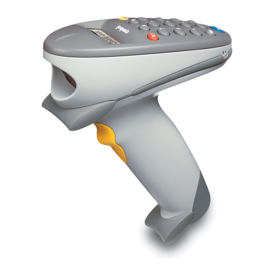
Phaser series scanner
Hide thumbs
Also See for Phaser P460:
- Product reference manual (198 pages) ,
- Quick reference manual (17 pages) ,
- Brochure (8 pages)
Table of Contents
Advertisement
Quick Links
QUESTIONS?
Ask the experts at POSMicro.com.
1.800.241.6264
Live Chat Now
support@POSMicro.com
Monday - Friday 6 AM to 5 PM Pacific Time
1.800.241.6264
Motorola Phaser P460
Manual
More information available at
BULk DISCOUNTS
FREE SHIPPING*
*Free ground shipping to the continental USa on orders over $100.
For Help Call
POSMicro.com
SE HaBLa
ESpañOL
Advertisement
Table of Contents

Related Manuals for Symbol Phaser P460


Summary of Contents for Symbol Phaser P460
- Page 1 For Help Call 1.800.241.6264 Motorola Phaser P460 Manual More information available at POSMicro.com QUESTIONS? BULk DISCOUNTS SE HaBLa Ask the experts at POSMicro.com. ESpañOL FREE SHIPPING* 1.800.241.6264 Live Chat Now support@POSMicro.com Monday - Friday 6 AM to 5 PM Pacific Time...
- Page 2 Phaser Series Scanner About This Manual Table Of Contents Index Copyright Product Reference Guide...
- Page 3 © 1998 by Symbol Technologies, Inc. All rights reserved. No part of this publication may be reproduced or used in any form, or by any electrical or mechanical means, without permission in writing from Symbol. This includes electronic or mechanical means, such as photocopying, recording, or information storage and retrieval systems.
-
Page 4: Table Of Contents
Contents About This Manual Introduction ..............v Chapter Descriptions . - Page 5 Phaser Series Scanner Product Reference Guide Wand Emulation, OCIA, OCR, Keyboard Wedges........2-7 Chapter 3.
- Page 6 Contents Language ..............5-12 Date Separator .
- Page 7 Phaser Series Scanner Product Reference Guide Enable/Disable Code 39 Full ASCII ..........5-50 Convert Code 39 to Code 32 .
-
Page 8: About This Manual
About This Manual Introduction The Phaser P 460 Series Scanner Product Reference Guide provides general instructions for setup, operation, troubleshooting, maintenance, and programming the Phaser scanners. Chapter Descriptions Chapter 1, The Phaser P 460 Series Scanner, describes the Phaser, the battery, and the Phaserlink Cradle. -
Page 9: Related Publications
Phaser Series Scanner Product Reference Guide Sequential lists (e.g., those that describe step-by-step procedures) appear as numbered lists. Related Publications P 360/460 Memory Scanner Quick Reference Guide, p/n 70-33628-xx PL 460 Cradle Quick Reference Guide, p/n 70-33657-xx MCL Designer for P 460 Series Scanners User’s Guide, p/n 70-35152-xx MCL Link for P 460 Series Scanners User’s Guide, p/n 70-35153-xx Service Information If you have a problem with your equipment, contact the Symbol Support Center. -
Page 10: Symbol Support Center
About This Manual Symbol Support Center For service information, warranty information or technical assistance, contact or call the Symbol Support Center in: United States Canada Symbol Technologies, Inc. Symbol Technologies Canada, Inc. One Symbol Plaza 2540 Matheson Boulevard East Holtsville, NY 11742-1300 Mississauga, Ontario, Canada L4W 422 1-800-653-5350 (905) 629-7226... -
Page 11: Introduction
Chapter 1 The Phaser Series Scanner Introduction The Phaser P 460 Memory Scanner brings new flexibility and economy to data capture and data management in retail operations. The Phaser Scanner has an integrated keypad and display, and is able to operate in both corded and battery-powered cordless modes. This provides advanced point-of-sale scanning and also allows the Phaser to be used for other in- store tasks such as delivery, inventory, pricing, and even gift registry. -
Page 12: The Cradle
Phaser Series Scanner Product Reference Guide The Cradle The Phaserlink Cradle acts as a stand, host communication interface, and a charger for the Phaser Scanner. It can sit on a desktop or be wall-mounted - whichever is more convenient. It receives data from the scanner via connectors in the bottom of the scanner and the top of the cradle. -
Page 13: Chapter 2. Set Up
Chapter 2 Set Up Introduction This chapter covers the procedures for setting up the Phaser and its accessories. Unpacking Remove the scanner from its packing and inspect it for damage. If the scanner was damaged in transit, call one of the telephone numbers listed in the section Symbol Support Center page vii. - Page 14 Phaser Series Scanner Product Reference Guide 2. Plug the modular connector on the cable into the receptacle in the bottom of the Phaser handle. The twist-lock can be slipped down the cable to facilitate connecting. Figure 2-1. Connecting the Cable to the Phaser 3.
-
Page 15: Disconnecting Cables
Set Up Disconnecting Cables To disconnect the scanner cable: 1. Power down all the devices connected to the scanner. 2. Remove the cable by twisting the twist-lock 1/8 turn counter-clockwise and pulling the cable out. Setting Up the Cradle On the bottom of the cradle are three ports. COM1 connects to the host computer, COM2 is used for daisy-chaining multiple base stations together, and the Power port supplies power to the cradle. -
Page 16: Scanner Power Options
Phaser Series Scanner Product Reference Guide Scanner Power Options Two power options are available: Battery Power Supply (“Charging”) Cable Charging the Battery Before its first use, the Phaser battery must be charged. Using the Cradle 1. Connect the power supply to the power input jack on the cradle. 2. -
Page 17: Using The Charging Cable
Set Up Using the Charging Cable Note: For charging, the cable may or may not be connected to the host. 1. Connect the cable to the scanner. 2. Connect the power supply to the power jack on the cable. 3. Connect the power supply to a receptacle supplying AC power of the proper voltage level. -
Page 18: Rs-232 Power Supply Operation
Phaser Series Scanner Product Reference Guide RS-232 Power Supply Operation 1. Make sure all host devices are powered down. 2. Plug the connector at the end of the scanner’s or cradle’s cable into an appropriate RS-232 receiving port on the host device. 3. -
Page 19: Using A Synapse Cable With The Scanner
Set Up Using a Synapse Cable with the Scanner 1. Connect the Synapse Adapter cable into the bottom of the scanner. 2. Connect the Synapse Adapter cable to the Synapse Interface cable . 3. Connect the Synapse Adapter cable’s flying power lead to the receptacle in the Synapse Interface cable (refer to Figure 2-4). -
Page 20: Chapter 3. Operation
When the unit is initially powered up (e.g., when a new battery is inserted), it displays the system start-up banner. Alternatively, the scanner can be reset manually using the <FN><*> key combination. The system banner appears as follows: SYMBOL TECHNOLOGIES Phaser P460 Figure 3-1. Banner Screen... -
Page 21: Batch Application
Phaser Series Scanner Product Reference Guide After 10 seconds, the System Banner is replaced by the system initialization screen: SYMBOL TECHNOLOGIES INITIALIZING ... Figure 3-2. Initialization Screen and finally (after about 5 seconds of initialization), the scanner enters either the BATCH scanning screen or the POS scanning screen, depending on whether the unit is attached to a communications cable or not. -
Page 22: Data Upload
Operation The screen displays the scanned code (up to 25 characters), the current record number and the maximum record number. The function initiates with the most recently scanned code, and pressing the up and down arrow keys move through the stored data. Press <ENTER> or <FN><BK>... -
Page 23: Pos Application
System Menu, press the <FN>* key combination to reset the scanner, and then <FN><BK> within the first 10 seconds after the power up beep (while the Banner Screen on page 3-1 is still shown). The scanner displays: Phaser P460 Scanner 0. System Setup Figure 3-11. Setup Screen... - Page 24 Operation Pressing the Up and Down keys scrolls through the menu of available setup options: 0. System Setup 1. App. Control 2. Parameter Control 3. System Status 4. Erase File 5. Version 9. Return to App Alternatively, press the associated numeric key to select the setup option directly (for advanced users who are already familiar with the options).
- Page 25 Phaser Series Scanner Product Reference Guide System Setup Options This group of options perform basic system functions. Within this option are the Set Date, Set Time, Set Contrast and Back To Main functions. Set Date Sets the date of the internal clock of the scanner. The scanner displays its current date value, and provides a prompt for the user to enter the new date.
- Page 26 Operation Set Default App Restores the default application described above. The default application overwrites any downloaded application. (This option may be used to restore functionality to a scanner which has been loaded with a defective application.) Prior to resetting the default application, the user is prompted to confirm this operation: Reset Default App? <EN>=Y <BK>=N...
- Page 27 Phaser Series Scanner Product Reference Guide Erase File Allows you to erase the data. All data files must be uploaded from the scanner before erasing a file. A screen prompts you to indicate which file is to be erased: Which File: Figure 3-13.
-
Page 28: Scanning
Operation Scanning The scanner ships with the default application and default parameters that is ready-to-use right out of the box. If this is not what you need for your application, refer to the MCL Designer Manual for programming instructions and Chapter 5, Parameter Menus scanning and communications parameters. -
Page 29: Scan The Entire Symbol
Phaser Series Scanner Product Reference Guide Scan the Entire Symbol Your scan beam must cross every bar and space on the symbol. The larger the symbol, the farther away you should hold the scanner. Hold the scanner closer for symbols with bars that are close together. A short, high tone beep indicates a good decode. -
Page 30: Phaser Decode Zone
Operation Phaser Decode Zone 15.6 in. 39.6 cm 10 in. 25.4 cm Width 5 in. 12.7 cm 0 in. 0 cm Field 5 in. 12.7 cm 5 mil 10 in. 7.5 mil 25.4 cm 10 mil 15.6 in. 39.6 cm 100% UPC 15 mil 20 mil... -
Page 31: Keypad Operation
Phaser Series Scanner Product Reference Guide Keypad Operation Instead of scanning a bar code, you can enter the bar code’s data using the keypad on the top of the scanner. To enter numeric characters, press the number key on the keypad. A high- pitched click lets you know that the entry was accepted. - Page 32 Operation Figure 3-18. Phaser Keypad 3-13...
-
Page 33: Troubleshooting
Phaser Series Scanner Product Reference Guide Troubleshooting Nothing happens when you follow the operating instructions? You Should Check that the power supply is attached to the cradle or to the cable. Check for loose cable connections at the scanner, cradle, AC power supply, or host device. -
Page 34: Chapter 4. Maintenance And Specifications
Chapter 4 Maintenance And Specifications Introduction This chapter explains how to maintain your scanner and the specifications for it. Maintenance Do not allow any abrasive material to touch the scanner window. Remove any dirt particles with a damp cloth. Wipe the scanner window using a damp cloth, and if necessary, a non-ammonia based detergent. -
Page 35: Removing The Battery
Phaser Series Scanner Product Reference Guide Removing the Battery 1. Slide the battery compartment release switch down. 2. Remove the battery compartment cover. Battery Compartment Cover Battery Release Switch Figure 4-1. Removing the Battery Compartment Cover 3. Slide the battery towards the bottom of the scanner. 4. -
Page 36: Charge Status Led Indications
Maintenance And Specifications Charge Status LED Indications The LED indicator on the cradle uses flashing patterns to display the charger status, as shown in the table below. Table 4-1. Cradle LED Indications Status The scanner is not in the cradle. Blinking Slowly The scanner is properly seated in the cradle, but charging has not begun. -
Page 37: Technical Specifications
Phaser Series Scanner Product Reference Guide Technical Specifications Table 4-2. Technical Specifications Item Description Decode Capability The Phaser can be programmed to decode the following code types: UPC/EAN, Bookland EAN, Code 39, Code 39 Full ASCII, Trioptic Code 39, Code 93, Codabar, Interleaved 2 of 5, Code 128, EAN 128, Discrete 2 of 5, MSI Plessey, and Coupon Code. -
Page 38: Cradle Pin-Outs
Maintenance And Specifications Table 4-2. Technical Specifications (Cont’d) Item Description Dimensions Height 7.0 in. (17.8 cm) Width 9.2 in. (13.5 cm) Depth 3.5 in. (9.8 cm) Laser Classifications CDRH Class II IEC Class 1 IEC 825 Class 2 Cradle Pin-outs The following table shows the pin-outs for both COM1 and COM2 on the cradle. -
Page 39: Beeper Indications
Phaser Series Scanner Product Reference Guide Beeper Indications Table 4-4. Beeper Indications Beeper Sequence Indication Standard Use Short high tone A bar code symbol was decoded (if decode beeper is enabled). 4 Beeps - long low tone A transmission error has been detected in a scanned symbol. The data is ignored. -
Page 40: Chapter 5. Parameter Menus
Chapter 5 Parameter Menus Introduction This chapter has the optional parameter bar codes necessary to program the Phaser scanner. Operational Parameters The Phaser is shipped with the settings shown in Table 5-1. These default values are stored in non-volatile memory and are preserved even when the scanner is powered down. You can change these default values by scanning the appropriate bar codes included in this manual. - Page 41 Phaser Series Scanner Product Reference Guide The following table lists the defaults for all parameters. If you wish to change any option, scan the appropriate bar code(s). Table 5-1. Default Table Parameter Default Page Number Set Default Parameter All Defaults RS-232 Host Type Standard Sleep Time...
- Page 42 Parameter Menus Table 5-1. Default Table (Cont’d) Parameter Default Page Number UPC/EAN UPC-A Enable 5-25 UPC-E Enable 5-25 UPC-E1 Disable 5-25 EAN-8 Enable 5-26 EAN-13 Enable 5-26 Bookland EAN Disable 5-27 Decode UPC/EAN Supplementals Ignore 5-28 Decode UPC/EAN Supplemental Redundancy 5-29 Transmit UPC-A Check Digit Enable...
- Page 43 Phaser Series Scanner Product Reference Guide Table 5-1. Default Table (Cont’d) Parameter Default Page Number Code 128 Code 128 Enable 5-41 UCC/EAN-128 Enable 5-42 Code 39 Code 39 Enable 5-43 Trioptic Code 39 Disable 5-44 Set Length(s) for Code 39 2 to 55 5-46 Code 39 Check Digit Verification...
- Page 44 Parameter Menus Table 5-1. Default Table (Cont’d) Parameter Default Page Number Discrete 2 of 5 Discrete 2 of 5 Disable 5-60 Set Length(s) for D 2 of 5 5-61 Codabar Codabar Disable 5-63 Set Lengths for Codabar 5-55 5-65 CLSI Editing Disable 5-66 NOTIS Editing...
- Page 45 Phaser Series Scanner Product Reference Guide Table 5-1. Default Table (Cont’d) Parameter Default Page Number RS-232C RS-232 Host Type Standard 5-10 Baud Rate 9600 5-78 Parity None 5-79 Check Receive Errors Disable 5-81 Hardware Handshaking None 5-83 Software Handshaking None 5-84 Host Serial Response Time-out 2 Sec.
-
Page 46: Set Default Parameter
Parameter Menus Set Default Parameter Scanning this bar code returns all parameters to the values listed in Table 5-1. SET ALL DEFAULTS... -
Page 47: Host Type
Phaser Series Scanner Product Reference Guide Host Type RS-232C Host Types Most RS-232C hosts work fine with the default settings, however, three RS-232C hosts are set up with their own parameter default settings. Selecting the ICL, Fujitsu or Nixdorf RS- 232C host interface sets the defaults listed below. - Page 48 Parameter Menus Host Type RS-232C Host Types Selecting the ICL, Fujitsu, or Nixdorf RS-232C host interface enables the transmission of Code ID Characters as listed below. These Code ID Characters are not programmable and are separate from the Transmit Code ID feature. The Transmit Code ID feature should not be enabled for these hosts.
- Page 49 Phaser Series Scanner Product Reference Guide Host Type RS-232C Host Types Scan the appropriate bar code below to select an RS-232C Host Interface. STANDARD RS-232C ICL RS-232C NIXDORF RS-232C Mode A NIXDORF RS-232C Mode B FUJITSU RS-232C 5-10...
-
Page 50: Sleep Time
Parameter Menus Sleep Time Scan the bar code below to select how long the scanner will “stay awake” (not power down) in seconds after a trigger pull or a key press. First scan this bar code, then enter a range from 05 to 32, using the numeric bar codes on page 5-90. -
Page 51: Date Separator
Phaser Series Scanner Product Reference Guide Date Separator Scan the appropriate bar code below to select which separator to use when displaying the date. Choose FORWARD SLASH, DASH, COLON or NONE. FORWARD SLASH (/) DASH (-) COLON (:) NONE 5-12... -
Page 52: Hour Type
Parameter Menus Hour Type Scan the appropriate bar code below to select how to display the hour and transmit it to the host device. Choose 12 HOUR (6:00 pm) or 24 HOUR (18:00). 24 HOUR 12 HOUR 5-13... -
Page 53: Decimal Separator
Phaser Series Scanner Product Reference Guide Decimal Separator Scan the appropriate bar code below to select what separator to display when you hit the decimal point key on the keypad. Choose DECIMAL POINT (.) or COMMA (,). DECIMAL POINT (.) COMMA (,) 5-14... -
Page 54: Date Format
Parameter Menus Date Format Scan the appropriate bar code below to select how to format the date when it is displayed and transmitted to the host device. Choose MM/DD/YYYY or DD/MM/YYYY. MM/DD/YYYY DD/MM/YYYY 5-15... -
Page 55: Key Click
Phaser Series Scanner Product Reference Guide Key Click Scan the appropriate bar code below to select whether the keypad click is enabled or not. Choose ENABLE or DISABLE. ENABLE DISABLE 5-16... -
Page 56: Beeper Tone
Parameter Menus Beeper Tone Scan the appropriate bar code below to select a decode beep frequency (tone). Choose LOW FREQUENCY, MEDIUM FREQUENCY, or HIGH FREQUENCY. LOW FREQUENCY MEDIUM FREQUENCY HIGH FREQUENCY 5-17... -
Page 57: Beeper Volume
Phaser Series Scanner Product Reference Guide Beeper Volume Scan the appropriate bar code below to select a beeper volume. Choose LOW VOLUME, MEDIUM VOLUME, or HIGH VOLUME. LOW VOLUME MEDIUM VOLUME HIGH VOLUME 5-18... -
Page 58: Laser On Time
Parameter Menus Laser On Time This parameter sets the maximum time decode processing continues during a scan attempt. It is programmable in 0.1 second increments from 0.5 to 9.9 seconds. Scan the bar code below to set a Laser On Time. Next scan two numeric bar codes beginning on page 5-90 that correspond to the desired time. -
Page 59: Beep After Good Decode
Phaser Series Scanner Product Reference Guide Beep After Good Decode Scan the appropriate bar code below to select whether or not the scanner beeps after a good decode. If DO NOT BEEP is selected, the beeper still operates during parameter menu scanning and indicates error conditions. -
Page 60: Transmit "No Read" Message
Parameter Menus Transmit “No Read” Message Scan the appropriate bar code below to select whether or not a “No Read” message is transmitted. When enabled, if a symbol does not decode, “NR” is transmitted. When disabled, if a symbol does not read, nothing is sent to the host. ENABLE NO READ DISABLE NO READ 5-21... -
Page 61: Linear Code Type Security Level
Phaser Series Scanner Product Reference Guide Linear Code Type Security Level The Phaser offers four levels of decode security for linear code types (e.g., Code 39, Interleaved 2 of 5). Higher security levels are selected for decreasing levels of bar code quality. As security levels increase, the scanner’s aggressiveness decreases. -
Page 62: Linear Security Level 3
Parameter Menus Linear Code Type Security Level (Cont’d) Linear Security Level 3 Code types other than the following must be successfully read twice before being decoded. The following codes must be read three times: Code Type Length MSI Plessey 4 or less D 2 of 5 8 or less I 2 of 5... -
Page 63: Bi-Directional Redundancy
Phaser Series Scanner Product Reference Guide Bi-directional Redundancy This parameter is only valid when a Linear Code Type Security Level (see page 5-22) is enabled. When this parameter is enabled, a bar code must be successfully scanned in both directions (forward and reverse) before being decoded. ENABLE BI-DIRECTIONAL REDUNDANCY DISABLE BI-DIRECTIONAL REDUNDANCY 5-24... -
Page 64: Enable/Disable Upc-E/Upc-A/Upc-E1
Parameter Menus Enable/Disable UPC-E/UPC-A/UPC-E1 Scan the appropriate bar code below to enable or disable UPC-E or UPC-A. DISABLE UPC-E ENABLE UPC-E ENABLE UPC-A DISABLE UPC-A DISABLE UPC-E1 ENABLE UPC-E1 5-25... -
Page 65: Enable/Disable Ean-8/Ean-13
Phaser Series Scanner Product Reference Guide Enable/Disable EAN-8/EAN-13 Scan the appropriate bar code below to enable or disable EAN-8 or EAN-13. ENABLE EAN-8 DISABLE EAN-8 ENABLE EAN-13 DISABLE EAN-13 5-26... -
Page 66: Enable/Disable Bookland Ean
Parameter Menus Enable/Disable Bookland EAN Scan the appropriate bar code below to enable or disable Bookland EAN. ENABLE BOOKLAND EAN DISABLE BOOKLAND EAN 5-27... -
Page 67: Decode Upc/Ean Supplementals
Phaser Series Scanner Product Reference Guide Decode UPC/EAN Supplementals Supplementals are characters (either 2 or 5) that are added on according to specific code format conventions (e.g., UPC A+2, UPC E+2, EAN 8+2). Three options are available. If Decode UPC/EAN with supplementals is selected, UPC/EAN symbols without supplemental characters are not decoded. -
Page 68: Decode Upc/Ean Supplemental Redundancy
Parameter Menus Decode UPC/EAN Supplemental Redundancy With Autodiscriminate UPC/EAN Supplementals selected, this option adjusts the number of times a symbol without supplementals is decoded before transmission. The range is from two to 20 times. Five or above is recommended when decoding a mix of UPC/EAN symbols with and without supplementals, and the autodiscriminate option is selected. -
Page 69: Transmit Upc-A/Upc-E/Upc-E1 Check Digit
Phaser Series Scanner Product Reference Guide Transmit UPC-A/UPC-E/UPC-E1 Check Digit Scan the appropriate bar code below to transmit the symbol with or without the UPC-A, UPC-E, or UPC-E1 check digit. TRANSMIT UPC-A CHECK DIGIT DO NOT TRANSMIT UPC-A CHECK DIGIT TRANSMIT UPC-E CHECK DIGIT DO NOT TRANSMIT UPC-E CHECK DIGIT TRANSMIT UPC-E1 CHECK DIGIT... -
Page 70: Upc-A Preamble
Parameter Menus UPC-A Preamble Three options are given for lead-in characters for UPC-A symbols transmitted to the host device: transmit system character only, transmit system character and country code (“0” for USA), and no preamble transmitted. The lead-in characters are considered part of the symbol. NO PREAMBLE (<DATA>) SYSTEM CHARACTER... -
Page 71: Upc-E Preamble
Phaser Series Scanner Product Reference Guide UPC-E Preamble Three options are given for lead-in characters for UPC-E symbols transmitted to the host device: transmit system character only, transmit system character and country code (“0” for USA), and no preamble transmitted. The lead-in characters are considered part of the symbol. NO PREAMBLE (<DATA>) SYSTEM CHARACTER... -
Page 72: Upc-E1 Preamble
Parameter Menus UPC-E1 Preamble Three options are given for lead-in characters for UPC-E1 symbols transmitted to the host device: transmit system character only, transmit system character and country code (“0” for USA), and no preamble transmitted. The lead-in characters are considered part of the symbol. NO PREAMBLE (<DATA>) SYSTEM CHARACTER... -
Page 73: Convert Upc-E To Upc-A
Phaser Series Scanner Product Reference Guide Convert UPC-E to UPC-A This parameter converts UPC-E (zero suppressed) decoded data to UPC-A format before transmission. After conversion, data follows UPC-A format and is affected by UPC-A programming selections (e.g., Preamble, Check Digit). Scanning DO NOT CONVERT UPC-E TO UPC-A allows you to transmit UPC-E (zero suppressed) decoded data. -
Page 74: Convert Upc-E1 To Upc-A
Parameter Menus Convert UPC-E1 to UPC-A This parameter converts UPC-E1 decoded data to UPC-A format before transmission. After conversion, data follows UPC-A format and is affected by UPC-A programming selections (e.g., Preamble, Check Digit). Scanning DO NOT CONVERT UPC-E1 TO UPC-A allows you to transmit UPC-E1 decoded data. -
Page 75: Ean Zero Extend
Phaser Series Scanner Product Reference Guide EAN Zero Extend If this parameter is enabled, five leading zeros are added to decoded EAN-8 symbols to make them compatible in format to EAN-13 symbols. Disabling this parameter returns EAN-8 symbols to their normal format. ENABLE EAN ZERO EXTEND DISABLE EAN ZERO EXTEND 5-36... -
Page 76: Convert Ean-8 To Ean-13 Type
Parameter Menus Convert EAN-8 to EAN-13 Type When EAN Zero Extend is enabled, this parameter gives you the option of labeling the extended symbol as either an EAN-13 bar code, or an EAN-8 bar code. When EAN Zero Extend is disabled, this parameter has no effect on bar code data. TYPE IS EAN-13 TYPE IS EAN-8 5-37... -
Page 77: Upc/Ean Security Level
Phaser Series Scanner Product Reference Guide UPC/EAN Security Level The Phaser offers four levels of decode security for UPC/EAN bar codes. Increasing levels of security are provided for decreasing levels of bar code quality. There is an inverse relationship between security and scanner aggressiveness, so be sure to choose only that level of security necessary for any given application. -
Page 78: Upc/Ean Security Level 2
Parameter Menus UPC/EAN Security Level (Cont’d) UPC/EAN Security Level 2 If you are experiencing mis-decodes of poorly printed bar codes, and the mis-decodes are not limited to characters 1, 2, 7, and 8, select this security level. UPC/EAN SECURITY LEVEL 2 UPC/EAN Security Level 3 If you have tried Security Level 2, and are still experiencing misdecodes, select this security level. -
Page 79: Upc/Ean Coupon Code
Phaser Series Scanner Product Reference Guide UPC/EAN Coupon Code When this parameter is enabled, the Phaser decodes UPC-A, UPC-A with 2 supplemental characters, UPC-A with 5 supplemental characters, and UPC-A/EAN128 bar codes. UPC-A with supplemental characters need not be enabled. ENABLE UPC/EAN COUPON CODE DISABLE UPC/EAN COUPON CODE 5-40... -
Page 80: Enable/Disable Code 128
Parameter Menus Enable/Disable Code 128 Scan the appropriate bar code below to enable or disable Code 128. ENABLE CODE 128 DISABLE CODE 128 Note: The “|” character and the NULL character cannot be embedded in the barcode to be scanned when using Code 128. 5-41... -
Page 81: Enable/Disable Ucc/Ean-128
Phaser Series Scanner Product Reference Guide Enable/Disable UCC/EAN-128 Scan the appropriate bar code below to enable or disable UCC/EAN-128. (See Appendix A for details on UCC/EAN-128.) ENABLE UCC/EAN-128 DISABLE UCC/EAN-128 Lengths for Code 128 No length setting is required for Code 128. The default setting is Any Length. 5-42... -
Page 82: Enable/Disable Code 39
Parameter Menus Enable/Disable Code 39 Scan the appropriate bar code below to enable or disable Code 39. ENABLE CODE 39 DISABLE CODE 39 5-43... -
Page 83: Enable/Disable Trioptic Code 39
Phaser Series Scanner Product Reference Guide Enable/Disable Trioptic Code 39 Trioptic Code 39 symbols always contain six characters. Trioptic Code 39 and Code 39 Full ASCII cannot be enabled simultaneously. If you get an error beep when enabling Trioptic Code 39, disable Code 39 Full ASCII and try again. To enable or disable Trioptic Code 39, scan the appropriate bar code below. -
Page 84: Set Lengths For Code 39
Parameter Menus Set Lengths for Code 39 Lengths for Code 39 may be set for any length, one or two discrete lengths, or lengths within a specific range. The length of a code refers to the number of characters (i.e., human readable characters), including check digit(s) the code contains. - Page 85 Phaser Series Scanner Product Reference Guide Set Lengths for Code 39 (Cont’d) Length Within Range - This option allows you to decode a code type within a specified range. For example to decode Code 39 symbols containing between 4 and 12 characters, first scan Code 39 Length Within Range.
-
Page 86: Code 39 Check Digit Verification
Parameter Menus Code 39 Check Digit Verification When enabled, this parameter checks the integrity of a Code 39 symbol to ensure it complies with specified algorithms. Only those Code 39 symbols which include a modulo 43 check digit are decoded when this parameter is enabled. -
Page 87: Transmit Code 39 Check Digit
Phaser Series Scanner Product Reference Guide Transmit Code 39 Check Digit Scan the appropriate bar code below to transmit the data with or without the check digit. TRANSMIT CODE 39 CHECK DIGIT (ENABLE) DO NOT TRANSMIT CODE 39 CHECK DIGIT (DISABLE) 5-48... -
Page 88: Enable/Disable Code 39 Full Ascii
Parameter Menus Enable/Disable Code 39 Full ASCII Scan the appropriate bar code below to enable or disable Code 39 Full ASCII. When enabled, the ASCII character set assigns a code to letters, punctuation marks, numerals, and most control keystrokes on the keyboard. The first 32 codes are non-printable and are assigned to keyboard control characters such as BACKSPACE and RETURN. -
Page 89: Convert Code 39 To Code 32
Phaser Series Scanner Product Reference Guide Convert Code 39 to Code 32 Scan the appropriate bar code below to enable or disable converting Code 39 to Code 32. Note: Code 39 must be enabled in order for this parameter to function. CONVERT CODE 39 TO CODE 32 (ENABLE) DO NOT CONVERT CODE 39 TO CODE 32... -
Page 90: Enable/Disable Code 93
Parameter Menus Enable/Disable Code 93 Scan the appropriate bar code below to enable or disable Code 93. ENABLE CODE 93 DISABLE CODE 93 5-51... -
Page 91: Set Lengths For Code 93
Phaser Series Scanner Product Reference Guide Set Lengths for Code 93 Lengths for Code 93 may be set for any length, one or two discrete lengths, or lengths within a specific range. The length of a code refers to the number of characters (i.e., human readable characters), including check digit(s) the code contains. - Page 92 Parameter Menus Set Lengths for Code 93 (Cont’d) Length Within Range - This option allows you to decode a code type within a specified range. For example to decode Code 93 symbols containing between 4 and 12 characters, first scan Code 93 Length Within Range. Then scan 0, 4, 1 and 2 (single digit numbers must always be preceded by a leading zero).
-
Page 93: Enable/Disable Interleaved 2 Of 5
Phaser Series Scanner Product Reference Guide Enable/Disable Interleaved 2 of 5 Scan the appropriate bar code below to enable or disable Interleaved 2 of 5. ENABLE INTERLEAVED 2 OF 5 DISABLE INTERLEAVED 2 OF 5 5-54... -
Page 94: Set Lengths For Interleaved 2 Of 5
Parameter Menus Set Lengths for Interleaved 2 of 5 Lengths for I 2 of 5 may be set for any length, one or two discrete lengths, or lengths within a specific range. The length of a code refers to the number of characters (i.e., human readable characters) the code contains and includes check digits. - Page 95 Phaser Series Scanner Product Reference Guide Set Lengths for Interleaved 2 of 5 (Cont’d) Length Within Range - This option allows you to decode a code type within a specified range. For example to decode I 2 of 5 symbols containing between 4 and 12 characters, first scan I 2 of 5 Length Within Range.
-
Page 96: I 2 Of 5 Check Digit Verification
Parameter Menus I 2 of 5 Check Digit Verification When enabled, this parameter checks the integrity of an I 2 of 5 symbol to ensure it complies with a specified algorithm, either USS (Uniform Symbology Specification), or OPCC (Optical Product Code Council). DISABLE USS CHECK DIGIT OPCC CHECK DIGIT... -
Page 97: Transmit I 2 Of 5 Check Digit
Phaser Series Scanner Product Reference Guide Transmit I 2 of 5 Check Digit Scan the appropriate bar code below to transmit the data with or without the check digit. TRANSMIT I 2 of 5 CHECK DIGIT (ENABLE) DO NOT TRANSMIT I 2 of 5 CHECK DIGIT (DISABLE) 5-58... -
Page 98: Convert I 2 Of 5 To Ean-13
Parameter Menus Convert I 2 of 5 to EAN-13 This parameter converts a 14 character I 2 of 5 code into EAN-13, and transmits to the host as EAN-13. In order to accomplish this, the I 2 of 5 code must be enabled, one length must be set to 14, and the code must have a leading zero and a valid EAN-13 check digit. -
Page 99: Enable/Disable Discrete 2 Of 5
Phaser Series Scanner Product Reference Guide Enable/Disable Discrete 2 of 5 Scan the appropriate bar code below to enable or disable Discrete 2 of 5. ENABLE DISCRETE 2 OF 5 DISABLE DISCRETE 2 OF 5 5-60... -
Page 100: Set Lengths For Discrete 2 Of 5
Parameter Menus Set Lengths for Discrete 2 of 5 Lengths for D 2 of 5 may be set for any length, one or two discrete lengths, or lengths within a specific range. The length of a code refers to the number of characters (i.e., human readable characters) the code contains, and includes check digits. - Page 101 Phaser Series Scanner Product Reference Guide Set Lengths for Discrete 2 of 5 (Cont’d) Length Within Range - This option allows you to decode a code type within a specified range. For example to decode D 2 of 5 symbols containing between 4 and 12 characters, first scan D 2 of 5 Length Within Range.
-
Page 102: Enable/Disable Codabar
Parameter Menus Enable/Disable Codabar Scan the appropriate bar code below to enable or disable Codabar. ENABLE CODABAR DISABLE CODABAR 5-63... -
Page 103: Set Lengths For Codabar
Phaser Series Scanner Product Reference Guide Set Lengths for Codabar Lengths for Codabar may be set for any length, one or two discrete lengths, or lengths within a specific range. The length of a code refers to the number of characters (i.e., human readable characters) the code contains. - Page 104 Parameter Menus Set Lengths for Codabar (Cont’d) Length Within Range - This option allows you to decode a code type within a specified range. For example to decode Codabar symbols containing between 4 and 12 characters, first scan Codabar Length Within Range. Then scan 0, 4, 1 and 2 (single digit numbers must always be preceded by a leading zero).
-
Page 105: Clsi Editing
Phaser Series Scanner Product Reference Guide CLSI Editing If enabled, this parameter strips the start and stop characters and inserts a space after the first, fifth, and tenth characters of a 14-character Codabar symbol. Note: Symbol length does not include start and stop characters. ENABLE CLSI EDITING DISABLE CLSI EDITING 5-66... -
Page 106: Notis Editing
Parameter Menus NOTIS Editing If enabled, this parameter strips the start and stop characters from a decoded Codabar symbol. ENABLE NOTIS EDITING DISABLE NOTIS EDITING 5-67... -
Page 107: Enable/Disable Msi Plessey
Phaser Series Scanner Product Reference Guide Enable/Disable MSI Plessey Scan the appropriate bar code below to enable or disable MSI Plessey. ENABLE MSI PLESSEY DISABLE MSI PLESSEY 5-68... -
Page 108: Set Lengths For Msi Plessey
Parameter Menus Set Lengths for MSI Plessey Lengths for MSI Plessey may be set for any length, one or two discrete lengths, or lengths within a specific range. The length of a code refers to the number of characters (i.e., human readable characters) the code contains, and includes check digits. - Page 109 Phaser Series Scanner Product Reference Guide Set Lengths for MSI Plessey (Cont’d) Length Within Range - This option allows you to decode a code type within a specified range. For example to decode MSI Plessey symbols containing between 4 and 12 characters, first scan MSI Plessey Length Within Range.
-
Page 110: Msi Plessey Check Digits
Parameter Menus MSI Plessey Check Digits These check digits at the end of the bar code verify the integrity of the data. At least one check digit is always required. Check digits are not automatically transmitted with the data. ONE MSI PLESSEY CHECK DIGIT TWO MSI PLESSEY CHECK DIGITS 5-71... -
Page 111: Transmit Msi Plessey Check Digit
Phaser Series Scanner Product Reference Guide Transmit MSI Plessey Check Digit Scan the appropriate bar code below to transmit the data with or without the check digit. TRANSMIT MSI PLESSEY CHECK DIGIT (ENABLE) DO NOT TRANSMIT MSI PLESSEY CHECK DIGIT (DISABLE) 5-72... -
Page 112: Msi Plessey Check Digit Algorithm
Parameter Menus MSI Plessey Check Digit Algorithm When the two MSI Plessey check digits option is selected, an additional verification is required to ensure integrity. Either of the two following algorithms may be selected. MOD 10/MOD 11 MOD 10/MOD 10 5-73... -
Page 113: Transmit Code Id Character
Phaser Series Scanner Product Reference Guide Transmit Code ID Character A code ID character identifies the code type of a scanned bar code. This may be useful when the scanner is decoding more than one code type. The code ID character precedes the decoded symbol. - Page 114 Parameter Menus Transmit Code ID Character (Cont’d) SYMBOL CODE ID CHARACTER AIM CODE ID CHARACTER NONE 5-75...
-
Page 115: Pause Duration
Phaser Series Scanner Product Reference Guide Pause Duration This parameter allows a pause to be inserted at any point in the data transmission. Pauses are set by scanning the bar code below followed by a two digit number (i.e. two bar codes), and are measured in 1/10 second intervals. -
Page 116: Rs-232C Parameters
Parameter Menus RS-232C Parameters Baud Rate Baud rate is the number of bits of data transmitted per second. The scanner's baud rate setting should match the data rate setting of the host device. If not, data may not reach the host device or may reach it in distorted form. - Page 117 Phaser Series Scanner Product Reference Guide Baud Rate (Cont’d) BAUD RATE 4800 BAUD RATE 9600 BAUD RATE 19,200 BAUD RATE 38,400 5-78...
-
Page 118: Parity
Parameter Menus Parity A parity check bit is the most significant bit of each ASCII coded character. Select the parity type according to host device requirements. If you select ODD parity, the parity bit has a value 0 or 1, based on data, to ensure that an odd number of 1 bits are contained in the coded character. - Page 119 Phaser Series Scanner Product Reference Guide Parity (Cont’d) Select MARK parity and the parity bit is always 1. MARK Select SPACE parity and the parity bit is always 0. SPACE If no parity is required, select NONE. NONE 5-80...
-
Page 120: Check Receive Errors
Parameter Menus Check Receive Errors Select whether or not the parity, framing, and overrun of received characters are checked. The type of parity used is selectable through the PARITY parameter. CHECK FOR RECEIVED ERRORS DO NOT CHECK FOR RECEIVED ERRORS 5-81... -
Page 121: Hardware Handshaking
Phaser Series Scanner Product Reference Guide Hardware Handshaking The data interface consists of an RS-232C port. The port has been designed to operate either with or without the hardware handshaking lines, RTS, Request to Send, and CTS, Clear to Send. If Standard RTS/CTS handshaking is selected, scan data is transmitted according to the following sequence: The scanner reads the CTS line for activity. - Page 122 Parameter Menus Hardware Handshaking (Cont’d) Scan the bar code below if no Hardware Handshaking is desired. NONE Scan the bar code below to select Standard RTS/CTS Hardware Handshaking. STANDARD RTS/CTS When RTS/CTS Option 1 is selected, the cradle asserts RTS before transmitting and ignores the state of CTS.
-
Page 123: Software Handshaking
Phaser Series Scanner Product Reference Guide Hardware Handshaking (Cont’d) When Option 2 is selected, RTS is always high or low (user-programmed logic level). However, the scanner waits for CTS to be asserted before transmitting data. If CTS is not asserted within two seconds (default), the scanner issues an error indication and discards the data. - Page 124 Parameter Menus Software Handshaking (Cont’d) ACK/NAK When this option is selected, after transmitting data, the cradle expects either an ACK, Acknowledge, or NAK, Negative Acknowledge, response from the host. Whenever a NAK is received, the cradle transmits the same data again and waits for either an ACK or NAK. After three unsuccessful attempts to send data when NAKs are received, the cradle issues an error indication and discards the data.
-
Page 125: Host Serial Response Time-Out
Phaser Series Scanner Product Reference Guide Software Handshaking (Cont’d) XON/XOFF An XOFF, Transmit Off, character turns the scanner transmission off until the scanner receives an XON, Transmit On, character. There are two situations for XON/XOFF: XOFF is received before the scanner has data to send. When the scanner has data to send, it then waits for an XON character before transmission. -
Page 126: Rts Line State
Parameter Menus RTS Line State Note: This only applies to the scanner in corded mode. It has no affect when uploading data through the cradle. Scan the appropriate bar code below to set the idle state of the Serial Host RTS line. Choose LOW RTS line state or HIGH RTS line state. -
Page 127: Stop Bit Select
Phaser Series Scanner Product Reference Guide Stop Bit Select The stop bit(s) at the end of each transmitted character marks the end of transmission of one character and prepares the receiving device for the next character in the serial data stream. The number of stop bits (one or two) selected depends on the number the receiving terminal is programmed to accommodate. -
Page 128: Beep On
Parameter Menus Beep on <BEL> When this parameter is enabled, the scanner beeps when a <BEL> character is detected on the RS-232C serial line. <BEL> is issued to gain a user's attention to indicate an illegal entry or other important event. BEEP ON <BEL>... -
Page 129: Numeric Bar Codes
Phaser Series Scanner Product Reference Guide Numeric Bar Codes For parameters requiring specific numeric values, scan the appropriately numbered bar code(s). 5-90... - Page 130 Parameter Menus Numeric Bar Codes (Cont’d) 5-91...
-
Page 131: Cancel
Phaser Series Scanner Product Reference Guide Numeric Bar Codes (Cont’d) Cancel If you make an error, or wish to change your selection, scan the bar code below. CANCEL 5-92... -
Page 132: Appendix A Bar Code Information
Appendix A Bar Code Information UCC/EAN-128 UCC/EAN-128 is a convention for printing data fields with standard Code 128 bar code symbols. UCC/EAN-128 symbols are distinguished by a leading FNC 1 character as the first or second character in the symbol. Other FNC 1 characters are used to delineate fields. When EAN-128 symbols are read, they are transmitted after special formatting strips off the leading FNC 1 character and replaces other FNC 1 characters with the ASCII 29 GS control character. - Page 133 Phaser Series Scanner Product Reference Guide Table A-1. Reading Standard Code128 & UCC/EAN 128 Standard Code UCC/EAN- Effect and Example Disable Disable No Code 128 symbols can be read. Disable Enable Read only symbols with leading FNC 1. Examples: FNC1 FNC1 ABCD E will be read as ABCD...
-
Page 134: Aim Code Identifiers
Bar Code Information AIM Code Identifiers Each AIM Code Identifier contains the three-character string ]cm where: = Flag Character (ASCII 93) = Code Character (see Table A-2) = Modifier Character (see Table A-3) Table A-2. Code Characters Code Character Code Type Code 39 Code 128/EAN-128 UPC/EAN... - Page 135 Phaser Series Scanner Product Reference Guide The modifier character is the sum of the applicable option values based on the following table. Table A-3. Modifier Characters Code Type Option Value Option Code 39 No check character or Full ASCII processing. Reader has checked one check character.
- Page 136 Bar Code Information Table A-3. Modifier Characters (Cont’d) Code Type Option Value Option Codabar No check digit processing. Reader has checked check digit. Reader has stripped check digit before transmission. Example: A Codabar bar code without check digit, 4123, is transmitted as ]F04123 Code 93 No options specified at this time.
- Page 137 Phaser Series Scanner Product Reference Guide Table A-3. Modifier Characters (Cont’d) Code Type Option Value Option Bookland EAN No options specified at this time. Always transmit 0. Example: A Bookland EAN bar code 123456789X is transmitted as ]X0123456789X According to AIM standards, a UPC with supplemental bar code is transmitted in one of the following formats: ]E0 (UPC chars) (terminator) ]E2 (supplemental) (terminator) or ]E2 (supplemental) (terminator) ]E0 (UPC chars) (terminator)
- Page 138 Bar Code Information Table A-4. ASCII Character Set ASCII Full ASCII Keystroke ASCII Full ASCII Keystroke Code 39 Code 39 Value Value Encode Char. Encode Char 1000 CTRL 2 1024 CTRL X 1001 CTRL A 1025 CTRL Y 1002 CTRL B 1026 CTRL Z 1003...
- Page 139 Phaser Series Scanner Product Reference Guide Table A-4. ASCII Character Set (Cont’d) ASCII Full ASCII Keystroke ASCII Full ASCII Keystroke Code 39 Code 39 Value Value Encode Char. Encode Char 1048 1073 1049 1074 1050 1075 1051 1076 1052 1077 1053 1078 1054...
- Page 140 Bar Code Information Table A-4. ASCII Character Set (Cont’d) ASCII Full ASCII Keystroke ASCII Full ASCII Keystroke Code 39 Code 39 Value Value Encode Char. Encode Char 1098 1113 1099 1114 1100 1115 1101 1116 1102 1117 1103 1118 1104 1119 1105 1120...
- Page 141 Phaser Series Scanner Product Reference Guide Table A-4. ASCII Character Set (Cont’d) ALT Keys Keystroke ALT Keys Keystroke ALT Keys Keystroke 2064 ALT 2 2075 ALT K 2086 ALT V 2065 ALT A 2076 ALT L 2087 ALT W 2066 ALT B 2077 ALT M...
- Page 142 Bar Code Information Table A-4. ASCII Character Set (Cont’d) PF Keys Keystroke PF Keys Keystroke PF Keys Keystroke 4001 PF 1 4009 PF 9 4017 PF 17 4002 PF 2 4010 PF 10 4018 PF 18 4003 PF 3 4011 PF 11 4019 PF 19...
- Page 143 Phaser Series Scanner Product Reference Guide Table A-4. ASCII Character Set (Cont’d) Numeric Keystroke Numeric Keystroke Numeric Keystroke Keypad Keypad Keypad 6042 6049 6056 6043 6050 6057 6044 Undefined 6051 6058 Enter 6045 6062 6059 Num Lock 6046 6063 6060 6047 6064 6048...
-
Page 144: Language
Index enable/disable code 39 full ASCII . . . 5-50 enable/disable code 93 ... . 5-52 accessories enable/disable discrete 2 of 5 ..5-61 optional . - Page 145 Phaser Series Scanner Product Reference Guide set lengths for D 2 of 5 ..5-62 5-63 set lengths for I 2 of 5 ..5-56 5-57 Data Review ......3-2 set lengths for MSI plessey .
- Page 146 Index Load New System ....3-6 POS application ....3-4 Scan Parameters .
-
Page 147: Tell Us What You Think
Tell Us What You Think... We’d like to know what you think about this Manual. Please take a moment to fill out this questionaire and fax this form to: (516) 738-3318, or mail to: Symbol Technologies, Inc. One Symbol Plaza M/S B-4 Holtsville, NY 11742-1300 Attn: Technical Publications Manager IMPORTANT: If you need product support, please call the appropriate cus-...
Need help?
Do you have a question about the Phaser P460 and is the answer not in the manual?
Questions and answers