Table of Contents
Advertisement
Advertisement
Table of Contents

Subscribe to Our Youtube Channel
Related Manuals for Speco O2B2


Summary of Contents for Speco O2B2
- Page 1 O2B2...
- Page 2 ’ ’ D i r e c t i o n s D i r e c t i o n s D i r e c t i o n s D i r e c t i o n s Be careful not to cause any physical damage by dropping or throwing the camera.
-
Page 3: Revision History
’ ’ Caution Any changes or modifications in construction of this device which are not explicitly approved by the party responsible for compliance could void the user’s authority to operate the equipment. Revision History Date Revision Details Oct 25 , 2013 First manual revision creation. -
Page 4: Table Of Contents
Getting Started ............................. 15 4.1. PC Requirement ............................. 15 4.2. Quick Installation Guide .......................... 16 4.2.1. Connect PC and O2B2 to network..............16 4.2.2. Install Speco-NVR ..................16 4.2.3. Remote video connection to O2B2 ..............19 4.2.4. Additional settings through connection to the Admin Page ........ 21 Troubleshooting ............................ -
Page 5: Introduction
It enables real time transmission of synchronized video of up to 1080p and audio data. Remote clients can connect to O2B2 for the real time video/audio data through various client solutions running on PC or smart device. Real time 2-way communication is available through bidirectional audio communication feature. -
Page 6: Specifications
Remote administration over IP network Web Viewer Internet Explorer 8 and up Client & Viewer Speco NVR (Windows) Dynamic IP DDNS support Speco DDNS (free of charge) support Video/Audio stream encryption ID and Password protection Security IP filtering for restricting administrative Rev.1.11 (Mar. 2014) -
Page 7: Applications Of O2B2
Server Active-X Supported SDK support HTTP Supported 1.3. Applications of O2B2 Security surveillance (buildings, stores, manufacturing facilities, parking lots, banks, government facilities, military, etc.) Remote monitoring (hospitals, kindergartens, traffic, public areas, etc.) eleconference (Bi-directional audio conference). Remote Learning, Internet broadcasting Weather and environmental observation Rev.1.11 (Mar. -
Page 8: Product Description
2.1. Contents The product package contains followings : Contents Description Remarks Main Unit O2B2 CVBS Cable 1EA Screws (3 pieces of 1 type) Accessories Anchors (3 pieces of 1 type) L-type wrench with six angles 1EA Software & User’s Guide... -
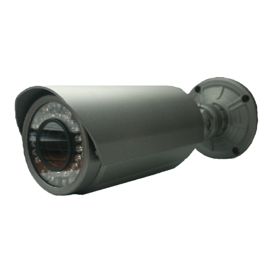
Page 9: Physical Description
’ ’ 2.3. Physical description 2.3.1. External View Figure 2-1. External view of O2B2 2.3.2. Dimensions Unit : mm Figure 2-2. Dimensions Rev.1.11 (Mar. 2014) -
Page 10: Connector Information
’ ’ 2.3.3. Connector Information Line Output Network (LAN) Sensor Input (white(+), Red(-)) Relay Output (Black(+), Yellow(-)) Mic/Line Input Power Figure 2-3. Connector information Rev.1.11 (Mar. 2014) -
Page 11: Functional Description
’ 2.4. Functional Description Power : Power input for supplying 12V DC, 1A power. Caution : If O2B2 is powered by PoE, do not plug in DC Jack with active DC power into DC power connector. Network (LAN) 100Mbps Ethernet connector (RJ-45) with PoE standard (802.3af). LED on the Ethernet connector shows... - Page 12 ’ ’ Relay Output Relay output is provided for connecting alarm devices or for remote on/off control of devices such as light. Relay is normal open and it will be closed upon alarm annunciation or remote on. The relay is capable of switching 30V AC/DC, 2A.
- Page 13 ’ ’ Factory Default Switch & Micro SD Card Eject switch There is a switch provided for returning the encoder box to factory default state or safely eject the micro SD card. Press the switch for 5 seconds while power is applied to return the encoder to factory default state or press for 1 second to unmount the micro SD card for safe removal.
-
Page 14: On Site Installation
’ ’ 3. On Site Installation Use Cables and conduits that are suitable for the installation. Particular attention should be paid in the installation so that no moisture is allowed to penetrate into the unit through the cables or conduits during the life time of the product. -
Page 15: Getting Started
Brief information for first time operation of O2B2 is provided in this chapter. 4.1. PC Requirement Audio/Video streaming data received from O2B2 can be displayed or stored in a PC running client programs. Minimum requirement of the PC is described below:... -
Page 16: Quick Installation Guide
(PC is needed to assign IP address to O2B2) 2. In the case of using PoE, connect the PC and O2B2 to the network using one of the following ways. If your LAN Switch does not support standard PoE, connect O2B2 as shown in dotted line in Figure 4-1. - Page 17 ’ ’ A d m i n P a g e B u t t o n O N S I P i n s t a l l e r Follow the sequence below for setting the IP parameter Run ONSIP installer Click (1) in ONSIP installer window.>...
- Page 18 ’ ’ Click on the field in (3) for sorting and rearranging the list. Select network mode that best suits from the drop down list in (5). You can choose either Static or ADSL and Auto (DHCP), respectively. If ADSL and Auto are selected, the fields in (6) are deactivated.
-
Page 19: Remote Video Connection To O2B2
4.2.3. Remote video connection to O2B2 1. Connection through Web Viewer Web Viewer offers simplest way of video connection to O2B2. For video connection, enter the IP address of O2B2 in the URL window of Internet Explorer as: Can be omitted the [e.g.] Port 80... - Page 20 SAVE button. You can see the live video when you click the live view button as below. When you exit Speco-NVR, you have to input the ID/PW, admin/1234. Details for Speco-NVR can be found in [Speco-NVR User’s Guide].
-
Page 21: Additional Settings Through Connection To The Admin Page
’ ’ 4.2.4. Additional settings through connection to the Admin Page All the parameters of new IP camera follows factory default values. For more sophisticated target application it is needed to change parameters. The admin page can be connected through “http://IP_Address:Port_Number/admin.htm”... -
Page 22: Troubleshooting
’ ’ 5. Troubleshooting 5.1. No power is applied In case of Standard PoE (Power over Ethernet) Power supply through standard PoE is possible only when the following conditions are met. 1. Standard PoE is supported on the product. 2. The LAN switch supports standard PoE. Make sure that both the IP camera and the LAN switch support standard PoE (IEEE 802.3af) In case of DC adapter If PoE is not applied, the power and network connection should be made through separate cables. -
Page 23: Cannot Connect To The Video
’ ’ 5.2. Cannot connect to the Video Check the status of the network connection through PING test. Try the following on your PC : Start > Run > Cmd > Ping IP address (Ex : Ping 172.16.42.51) If “Reply from ~”... -
Page 24: Windows Vista Or Windows 7
5.3. Windows Vista or Windows 7 Windows Vista and Windows 7 users need to configure UAC (User Access Control) and Privilege Level for proper recording and still video capture in Speco-NVR and Web Viewer. <Windows Vista> 1. UAC (User Access Control) configuration 1) Double-click “User Accounts”... - Page 25 ’ ’ <Windows 7> 1. UAC (User Access Control) configuration 1) Double-click “User Accounts” in control panel 2) Double-click “Change User Account Control setting” 3) Set to “Never notify” Rev.1.11 (Mar. 2014)
- Page 26 ’ ’ 2. Privilege Level Control 1) Select “NVR” icon on the desktop 2) Click right mouse button and select “properties” 3) Check “Privilege Level” in “Compatibility” tab Rev.1.11 (Mar. 2014)
-
Page 27: Technical Assistance
’ ’ 5.4. Technical Assistance If you need any technical assistance, please contact your dealer. For immediate service please provide the following information. Model name MAC address and Registration number Purchase date Description of the problem Error message Rev.1.11 (Mar. 2014) -
Page 28: Appendix A - Important Notice In Exchanging Sd Card (Micro Sd)
’ ’ Appendix A – Important Notice in Exchanging SD Card (Micro SD) SD Card is a non-volatile memory device for storing video and audio data on the product. Continued writing to the SD Card will cause wear-off of the memory cell. When you plug out the SD Card for replacement or other purpose, follow the steps below in order to prevent data loss.
Need help?
Do you have a question about the O2B2 and is the answer not in the manual?
Questions and answers