Omega i Series Manuals
Manuals and User Guides for Omega i Series. We have 6 Omega i Series manuals available for free PDF download: User Manual
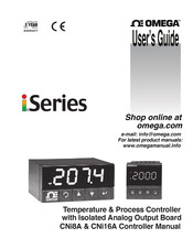
Omega i Series User Manual (73 pages)
Temperature & Process Controller
Brand: Omega
|
Category: Controller
|
Size: 1.72 MB
Table of Contents
Advertisement
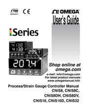
Omega i Series User Manual (72 pages)
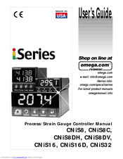
Process/Strain Gauge Controller
Brand: Omega
|
Category: Controller
|
Size: 1.94 MB
Table of Contents
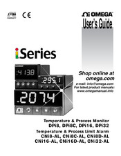
Omega i Series User Manual (57 pages)
Temperature & Process Monitor, Temperature & Process Limit Alarm
Brand: Omega
|
Category: Temperature Controller
|
Size: 1.25 MB
Table of Contents
Advertisement

Omega i Series User Manual (49 pages)
Temperature/Process Limit Controller
Brand: Omega
|
Category: Controller
|
Size: 1.44 MB
Table of Contents
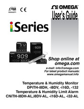
Omega i Series User Manual (43 pages)
Temperature & Humidity Monitor
Brand: Omega
|
Category: Controller
|
Size: 1.18 MB
Table of Contents
Omega i Series User Manual (72 pages)
i Series Process/Strain Gauge Controller
Brand: Omega
|
Category: Controller
|
Size: 1.35 MB
Advertisement