Sign In
Upload
Manuals
Brands
Icom Manuals
Transceiver
IC-706MKIIG
Icom IC-706MKIIG Manuals
Manuals and User Guides for Icom IC-706MKIIG. We have
7
Icom IC-706MKIIG manuals available for free PDF download: Service Manual, Instruction Manual, Quick Start Manual, Operation Manual, Operating Manual
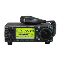
ICOM IC-706MKIIG Instruction Manual (76 pages)
HF/VHF/UHF ALL MODE TRANSCEIVER
Brand:
ICOM
| Category:
Transceiver
| Size: 2.12 MB
Table of Contents
Precautions
2
Explicit Definitions
2
Table of Contents
3
Unpacking
3
Panel Description
4
Front Panel
4
Function Switches
6
Rear and Side Panels
8
Beep/Sidetone Control
9
Technical Information
9
ACC Socket
9
Function Display
10
Microphone
11
Up/Down Switches
11
Lock Switch
11
PTT Switch
11
Installation and Connections
12
Grounding
12
Antenna
12
Single Body Mounting
13
Stand
13
Front Panel Separation
13
Front Panel Mounting
13
Required Connections
14
Advanced Connections
15
Power Supply Connections
16
Connecting the Ps-125 / Ps-85 DC Power Supply
16
Connecting a Non-Icom DC Power Supply
16
External Antenna Tuners and Linear Amplifier
17
Connecting the Ah-4
17
Connecting the At-180
17
Connecting the IC-Pw1
17
Frequency Settings
18
When First Applying Power (CPU Resetting)
18
Initial Settings
18
VFO Description
19
VFO Mode
19
Memory Mode
19
Frequency Setting
20
Band Selection
20
Programmable Tuning Steps
20
1Hz and 10 Hz Tuning Steps
20
1 Mhz Quick Tuning Step
21
Switch Flow Chart
21
Sub Dial Function
21
Mode Selection
22
Quick Band Change Function
22
Operating Mode Selection
22
Receive and Transmit
23
Functions for Receive
23
IF Shift Function
23
RIT Function
23
Noise Blanker
24
AGC Time Constant
24
Preamp and Attenuator
24
Peak Meter Hold
24
RF Gain and Squelch
25
Simple Band Scope
25
Optional Filter Selection
26
Filter Variations
26
Optional Filter Installation and Selection Tables SSB
26
Filter Presetting
26
Receive and Transmit
26
DSP Functions
27
ANF Function
27
Noise Reduction Function
27
Functions for Transmit
28
Output Power and MIC Gain
28
Meter Function
28
Setting Output Power
28
Speech Compressor
29
VOX Operation
29
Optional AT-180 Automatic Antenna Tuner Operation
30
Tuner Operation
30
Manual Tuning
30
Through Inhibit
30
Optional AH-4 Automatic Antenna Tuner Operation
31
AH-4 Setting Example
31
AH-4 Operation
31
PTT Tune Function
31
Split Frequency Operation
32
Quick Split Function
32
Programming Split Shift Frequency
32
Split Lock Function
32
Repeater Operation
33
Programming Duplex Shift Frequency
33
Tone Squelch Operation
34
Tone Scan Operation
34
One-Touch Repeater Function
35
Auto Repeater Function
35
1750 Hz Tone Burst
35
Functions for CW
36
Connections for CW
36
CW Operation
36
CW Pitch Control
37
CW Reverse Mode
37
Electronic CW Keyer
37
Setting the Electronic Keyer
37
Functions for RTTY
38
Connections for RTTY
38
Connections for AFSK
38
RTTY Operation
39
Presetting for RTTY
39
Tone Frequency
39
RTTY Reverse Mode
39
Packet Operation
40
Connections for Packet
40
Data Socket
40
Adjusting the Transmit Signal Output from the TNC
40
Swr
41
Measuring SWR
41
Spot Measurement
41
Plot Measurement
41
Memory and Scan Operation
42
Memory Channels
42
Memory Channel Selection
42
Memory Clearing
42
Memory/Call Programming
43
Programming in VFO Mode
43
Programming in Memory Mode
43
Frequency Transferring
44
Memory Names
44
Calling up Memory Names
44
Editing Memory Names
44
Memo Pads
45
Calling up a Frequency from a Memo Pad
45
Scan Types
46
Preparation
46
Programmed Scan
46
Priority Watch
46
Programmed Scan Operation
47
Memory Scan Operation
47
Select Memory Scan Operation
47
Remote Jack (CI-V) Information
48
CI-V Connection Example
48
Data Format
48
Command Table
49
Set Mode
50
General
50
Quick Set Mode Operation
50
Initial Set Mode Operation
50
Quick Set Mode Items
51
Maintenance
59
Fuse Replacement
59
Circuitry Fuse Replacement
59
Memory Backup
59
Troubleshooting
60
Optional Installations/Settings
62
Opening the Transceiver Case
62
UT-102 Voice Synthesizer Unit
62
CR-282 High-Stability Crystal Unit
63
IF Filters
63
UT-106 DSP Receiver Unit
64
MB-72 Carrying Handle
64
AT-180 Internal Switch Description
65
Specifications for the AT-180
65
AT-180 Inside Top Cover
65
Connector Information for ACC Socket
65
Internal Views
66
Top View
66
Bottom View
66
Specifications
69
Menu Guide
70
Initial Set Mode
70
Quick Set Mode
71
Version and Frequency Coverage
73
Installation Notes
74
Typical Amateur Radio Installation
74
EIRP Clearance Heights by Frequency Band
74
Forward Clearance, EIRP by Frequency Band
74
About Sp-7 External Speaker
75
Installation Note
75
Advertisement
Icom IC-706MKIIG Service Manual (86 pages)
HF/VHF/UHF ALL MODE TRANSCEIVER
Brand:
Icom
| Category:
Transceiver
| Size: 13.61 MB
Table of Contents
Ordering Parts
2
Repair Notes
2
Table of Contents
3
Specifications
4
Inside Views
5
Main and Filter Boards
5
Section 2 Inside Views
6
Circuit Description
6
Receiver Circuits
6
HF/50 Mhz RF CIRCUIT
6
Vhf and Uhf Rf Circuits
6
Preamplifier Circuit
7
1St Mixer Circuit
7
1St if Circuit
7
2Nd Mixer Circuit
7
If Shift Circuit
8
S-Meter Circuit
8
Squelch Circuit
8
Demodulator Circuits
8
Af Selector Switch (Main Board)
9
Af Amplifier Circuit
9
Microphone Amplifier Circuit
9
Vox Circuit (Main Board)
9
Transmitter Circuits
9
Fm Modulation Circuit
10
Transmitter if Circuit
10
Rf Circuit
10
Alc Circuit
10
Pll Circuits
11
Apc Circuit
11
Rf, Alc, Swr Meter Circuits
11
Main Loop Pll
11
2Nd lo and Reference Oscillator Circuits
12
Bfo Circuit
12
Logic Circuits
13
Band Selection Data
13
Sub Cpu Port Allocations
13
I/O Expander Port Allocations
13
Main Cpu Port Allocations
14
Adjustment Procedures
15
Connections
15
Preparation before Sarvicing
15
Required Test Equipment
15
Pll Adjustments
16
Transmitter Adjustments
16
Main Unit
17
Pll and Pa Units
17
Main and Filter Units
21
Pa Unit
21
Receiver Adjustments
22
Set Mode Adjustment
24
Section 8 Board Layouts
26
Parts List
26
Display Board
26
Front Unit
26
Main Board
28
Pll Unit
37
Pa Unit
42
Filter Board
45
Driver Board
47
Mechanical Parts and Disassembly
48
Semi-Conductor Information
52
Transistor and Fet’s
52
Diodes
52
Board Layout
53
Display Board
53
Display Board (Top View)
53
Display Board (Bottom View)
54
Main Board
55
Main Board (Bottom View)
56
Hpf and Driver Boards
57
Hpf Board (Top View)
57
Driver Board (Top View)
57
Hpf Board (Bottom View)
58
Driver Board (Bottom View)
58
Pa Unit (Top View)
59
Pa Unit (Bottom View)
60
Pll Unit (Top View)
61
Pll Unit (Bottom View)
62
Filter Unit
63
Filter Unit (Top View)
63
Filter Board (Bottom View)
64
Block Diagram
65
Voltage Diagram
66
Icom IC-706MKIIG Instruction Manual (75 pages)
HF/VHF/UHF All Mode Transceiver
Brand:
Icom
| Category:
Transceiver
| Size: 2.33 MB
Table of Contents
Important
2
Precautions
2
Explicit Definitions
2
Table of Contents
3
Unpacking
3
1 Panel Description
4
I Front Panel
4
I Function Switches
6
I Rear and Side Panels
8
Technical Information
9
I Function Display
10
Panel Description ..................................... 1
11
I Microphone (HM-103)
11
2 Installation and Connections
12
I Unpacking
12
I Grounding
12
I Antenna
12
I Installation
13
I Required Connections
14
I Advanced Connections
15
I Power Supply Connections
16
Installation and Connections .......... 9
17
I External Antenna Tuners and Linear Amplifier
17
3 Frequency Setting
18
I When First Applying Power (CPU Resetting)
18
I Initial Settings
18
I VFO Description
19
I Frequency Setting
20
I Mode Selection
22
4 Receive and Transmit
23
I Functions for Receive
23
I Functions for Transmit
28
I Split Frequency Operation
32
I Tone Squelch Operation
34
I Tone Scan Operation
34
I One-Touch Repeater
35
I Auto Repeater Function
35
I Functions for CW
36
I Functions for RTTY
38
I Packet Operation
40
I Swr
41
5 Memory and Scan Operation
42
I Memory Channels
42
I Memory Channel Selection
42
I Memory Clearing
42
I Memory/Call Programming
43
I Frequency Transferring
44
I Memory Names
44
I Memo Pads
45
I Scan Types
46
I Preparation
46
I Programmed Scan Operation
47
I Memory Scan Operation
47
I Select Memory Scan Operation
47
I Priority Watch
47
6 Remote Jack (CI-V) Information
48
7 Set Mode
50
I General
50
I Quick Set Mode Items
51
I Initial Set Mode Items
53
Scan Speed
56
8 Maintenance
59
I Fuse Replacement
59
I Memory Backup
59
I Cleaning
59
9 Troubleshooting
60
10 Optional Installations/Settings
62
I Opening the Transceiver Case
62
Voice Synthesizer Unit
62
I Cr-282 High - Stability Crystal Unit
63
I if Filters
63
High Stability Crystal Unit
63
Carrying Handle
64
Dsp Receiver Unit
64
I AT-180 Internal Switch Description
65
11 Internal Views
66
12 Options
67
Hand Microphone (HM-103)
67
13 Specifications
69
14 Menu Guide
70
Installation Notes
74
Advertisement
Icom IC-706MKIIG Service Manual (67 pages)
HF/VHF/UHF All Mode Transceiver
Brand:
Icom
| Category:
Transceiver
| Size: 11 MB
Table of Contents
Table of Contents
3
Specifications
4
Section 2Inside Views
6
Circuit Descripiton
6
Receiver Circuits
6
Transmitter Circuits
9
Pll Circuits
11
Logic Circuits
13
Adjustment Procedure
15
Preparation before Servicing
15
Pll Adjustments
16
Transmitter Adjustments
16
Receiver Adjustments
22
Set Mode Adjustment
24
Display Unit
26
Front Unit
26
Main Unit
27
Pll Unit
35
Filter Board
42
Driver Board
44
Filter Unit
52
Icom IC-706MKIIG Quick Start Manual (15 pages)
Brand:
Icom
| Category:
Radio
| Size: 0.4 MB
Icom IC-706MKIIG Operation Manual (3 pages)
Brand:
Icom
| Category:
Transceiver
| Size: 0.75 MB
Icom IC-706MKIIG Operating Manual (2 pages)
Brand:
Icom
| Category:
Transceiver
| Size: 0.21 MB
Advertisement
Related Products
Icom IC-706
Icom IC-706MKII
Icom IC-7000
Icom IC-707
ICOM IC-703
Icom IC-701
Icom IC-705
Icom IC-700
ICOM IC-726
Icom IC-7610
Icom Categories
Transceiver
Receiver
Repeater
Radio
Two-Way Radio
More Icom Manuals
Login
Sign In
OR
Sign in with Facebook
Sign in with Google
Upload manual
Upload from disk
Upload from URL