
Icom IC-701 Manuals
Manuals and User Guides for Icom IC-701. We have 2 Icom IC-701 manuals available for free PDF download: Instruction Manual
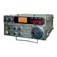
Icom IC-701 Instruction Manual (52 pages)
HF ALL Band All Solid State transceiver
Brand: Icom
|
Category: Transceiver
|
Size: 4.06 MB
Table of Contents
Advertisement
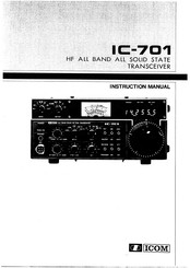
Icom IC-701 Instruction Manual (52 pages)
HF ALL BAND ALL SOLID STATE TRANSCEIVER
Brand: Icom
|
Category: Transceiver
|
Size: 8.23 MB
Table of Contents
Advertisement