Sign In
Upload
Manuals
Brands
Delta Manuals
Control Unit
CP2000 Series
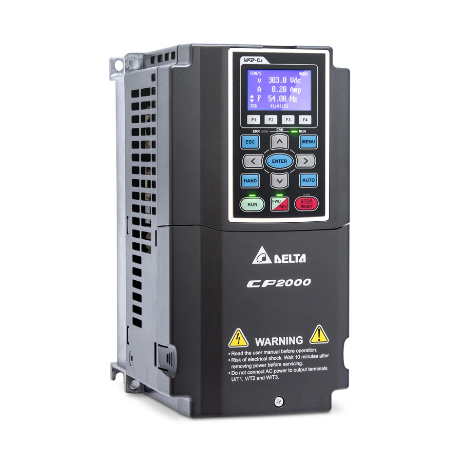
Delta CP2000 Series Manuals
Manuals and User Guides for Delta CP2000 Series. We have
4
Delta CP2000 Series manuals available for free PDF download: User Manual, Quick Start Manual
Delta CP2000 Series User Manual (734 pages)
Delta Fan/Pump Vector Control Drive
Brand:
Delta
| Category:
Control Unit
| Size: 40.84 MB
Table of Contents
Table of Contents
4
Chapter 1 Introduction
8
Receiving and Inspection
9
Nameplate Information
9
Model Name
10
Serial Number
10
Apply after Service by Mobile Device
11
Location of Service Link Label
11
Service Link Label
11
Scan QR Code to Apply
11
RFI Jumper
12
Isolating Main Power from Ground
13
Important Points Regarding Ground Connection
14
Pay Particular Attention to the Following Points
14
Floating Ground System (IT Systems)
14
RFI Jumper Must be Removed
15
RFI Jumper Can be Used
15
Dimensions
16
Mounting Clearance
36
Chapter 2 Installation
36
Minimum Mounting Clearance
37
Chapter 3 Unpacking
42
Unpacking
43
Frame H: Secure the Drive
53
The Lifting Hook
55
Weight of Models
57
Chapter 4 Wiring
60
System Wiring Diagram
62
Wiring
63
SINK(NPN)/SOURCE(PNP) Mode
66
Function of DC Link
67
Common DC Power and Common DC-BUS Link (Refer to Chart 1)
67
Common DC-BUS Link
67
Chapter 5 Main Circuit Terminals
70
Terminals for Connecting DC Reactor, External Brake Resistor, External Brake Resistor and DC Circuit
72
Main Circuit Diagram
73
Specifications of Main Circuit Terminals
76
Chapter 6 Control Terminals
86
Analog Input Terminals (AVI1, AVI2, ACI, ACM)
87
Digital Inputs (FWD, REV, MI1~MI8, COM)
87
Remove the Cover for Wiring
89
Specifications of Control Terminal
91
Remove the Terminal Block
93
Chapter 7 Optional Accessories
94
Brake Resistors and Brake Units Selection Chart
95
Specifications and Appearances of Brake Resistors
97
Aluminum Housed Resistors
98
Models and Specifications Comparison Table of Wire Wound Resistors
98
Definition for Brake Usage ED%
98
Non-Fuse Circuit Breaker
101
Fuse Specification Chart
103
AC/DC Reactor
105
AC Input Reactor Dimension and Specification
108
DC Reactor
117
Specifications of DC Reactors (Standard Item)
117
DC Reactor Dimension and Specification
119
The Following Table Is Spec. of Thdi that Delta AC Motor Drives Use with AC/DC Reactors
120
AC Output Reactor
120
Specifications of AC Output Reactors (Standard Item)
121
Motor Cable Length
123
Leakage Current to Affect the Motor and Counter Measurement
123
Surge Voltage to Affect the Motor and Counter Measurement
123
Requirements on Insulation Level of Curve B Motor
126
Sine-Wave Filter
127
Wiring of Non-Shielded Cable
127
Wiring of Shielded Cable
127
Zero Phase Reactor
130
EMC Filter
133
EMC Filter Dimension
136
EMC Filter Installation
143
General Precaution
143
Choose Suitable Motor Cable and Precautions
144
Digital Keypad
145
Kpc-Ce01
145
Descriptions of Keypad Functions
145
Descriptions of LED Functions
146
Dimension
148
RJ45 Extension Lead for Digital Keypad
148
Panel Mounting
149
Conduit Box Kit
151
Appearance of Conduit Box
151
Conduit Box Installation
154
Assembled to H3 (Conduit Box Kit)
160
Assembled to H2 (Stand Upright)
163
Fan Kit
166
Appearance of the Fan Kit
166
Fan Removal
171
Flange Mounting Kit
182
MKC-Afm1Installation
183
MKC-AFM Installation
184
Mkc-Bfm
186
MKC-BFM Installation
188
MKC-CFM Installation
191
Frame D0 & D & E Installation
195
USB/RS-485 Communication Interface IFD6530
198
Specifications
198
Preparations before Driver Installation
199
Driver Installation
200
LED Display
201
Chapter 8 Option Cards
202
Option Card Installation
203
Remove the Top Cover
203
Location to Install Extension Card
205
CMC-Eip01
205
Screws Specification for Optional Card Terminals
206
Communication Extension Card (Slot 1)
206
I/O / Relay Extension Card & 24V Power Extension Card (Slot 3)
206
Install and Uninstall of Extension Cards (I.e. Communication Card Installation)
208
Extension Card Installation
208
Disconnecting the Extension Card
209
Emc-D42A
210
Emc-D611A
210
Emc-R6Aa
211
CMC-Mod01
212
Features
212
Product File
212
Specifications
212
Install CMC-MOD01 to VFD-CP2000
213
Communication Parameters for VFD-CP2000 Connected to Ethernet
213
Disconnecting CMC- MOD01 from VFD-CP2000
214
Basic Registers
214
LED Indicator & Troubleshooting
215
CMC-Pd01
216
Product Profile
216
CMC-Dn01
218
CMC-Eip01
221
Connecting CMC-EIP01 to Network
222
Connecting CMC-EIP01 to VFD-CP2000
222
RJ-45 PIN Definition
222
Disconnecting CMC- EIP01 from VFD-CP2000
224
Emc-Cop01
226
Position of Terminal Resistance
226
Emc-Bps01
227
Delta Standard Fieldbus Cables
228
Chapter 9 Specifications
230
230V Series
231
460V Series
232
Efficiency Curve
234
575V Series
235
690V Series
236
General Specifications
238
Environment for Operation, Storage and Transportation
239
Specification for Operation Temperature and Protection Level
240
Derating of Ambient Temperature and Altitude
241
Chapter 10 Digital Keypad
244
Descriptions of Digital Keypad
245
Function of Digital Keypad KPC-CC01
248
Display Icon
249
Display Item
249
Parameter Setup
249
Copy Parameter
249
Keypad Locked
250
PLC Function
251
Fault Record
253
Display Setup
256
Time Setting
257
Language Setup
257
Start-Up
258
Main Page
258
PC Link
259
Other Display
262
Optional Accessory: RJ45 Extension Lead for Digital Keypad
262
Tpeditor Installation Instruction
263
Numeric Input Setting
270
Digital Keypad KPC-CC01 Fault Codes and Descriptions
272
Warning Code
273
Fault Occurred During Setup
274
File Copy Setting Fault Description
274
Unsupported Functions When Using Tpeditior on KPC-CC01 Keypad
276
Summary of Parameter Settings
278
00 Drive Parameters
278
Chapter 11 Summary of Parameters
278
01 Basic Parameters
285
Digital Input / Output Parameters
289
Analog Input / Output Parameters
294
Multi-Step Speed Parameters
298
Motor Parameters
299
Protection Parameters
302
Special Parameters
309
High-Function PID Parameters
311
Communication Parameters
312
PID Control Parameters
317
Advanced Parameters
318
PUMP Parameters
319
Application Parameters by Industry
320
Description of Parameter Settings
322
Drive Parameters
322
Parameter Reset
323
Start-Up Display Selection
324
Content of Multi-Function Display
324
Coefficient Gain in Actual Output Frequency
325
Software Version
326
Parameter Protection Password Input
326
Parameter Protection Password Setting
326
Control of Speed Mode
327
Load Selection
328
Carrier Frequency
328
PLC Command Mask (SOOC, SOOF, SOTC)
329
Source of the Master Frequency Command(Auto)
329
Source of the Operation Command (AUTO)
330
Stop Method
330
Control of Motor Direction
330
Memory of Digital Operator (Keypad) Frequency Command
331
User Defined Characteristics
331
Max. User Defined Value
332
User Defined Value
333
Switching from Auto Mode to Hand Mode
333
LOCAL/REMOTE Selection
333
Source of the Master Frequency Command(Hand)
334
Source of the Operation Command (HAND)
334
Digital Keypad STOP Function
334
Display Filter Time (Current)
335
Display Filter Time (Keypad)
335
Software Version (Date)
335
Maximum Output Frequency
336
Output Frequency of Motor 2(Base Frequency and Motor Rated Frequency)
336
Output Voltage of Motor 2(Base Frequency and Motor Rated Frequency)
336
MID-Point Frequency 1 of Motor 1
337
MID-Point Voltage 1 of Motor 1
337
MID-Point Voltage 1 of Motor 2
337
MID-Point Voltage 2 of Motor 1
337
MID-Point Voltage 2 of Motor 2
338
Min. Output Voltage of Motor 1
338
Min. Output Voltage of Motor 2
338
Common Settings of V/F Curve
339
Start-Up Frequency
340
Output Frequency Upper Limit
340
Output Frequency Lower Limit
341
JOG Deceleration Time
342
JOG Frequency
343
1St/4Th Accel./Decel. Frequency
343
S-Curve Deceleration Arrival Time 2
344
Skip Frequency 3 (Lower Limit)
344
Zero-Speed Mode
345
V/F Curve Selection
345
Optimal Acceleration/Deceleration Setting
347
Time Unit for Acceleration/Deceleration and S Curve
348
Time for Canopen Quick Stop
348
Deceleration Method
348
Digital Input/Output Parameter
349
2-Wire/3-Wire Operation Control
349
Input Terminal of I/O Extension Card (MI12/13/14/15)
350
UP/DOWN Key Mode
355
Constant Speed. the Accel. /Decel. Speed of the UP/DOWN Key
355
Digital Input Response Time
356
Digital Input Operation Setting
356
Multi-Function Output Setting
361
Terminal Counting Value Attained (Return to 0)
362
Preliminary Counting Value Attained (Not Return to 0)
362
Brake Delay Time
363
Output Current Level Setting for Multi-Function Output Terminals
364
Output Boundary for Multi-Function Output Terminals
364
External Operation Control Selection after Reset and Activate
364
Display the Status of Multi-Function Input Terminal
365
Status of Multi-Function Output Terminal
365
Display External Output Terminal Occupied by PLC
366
Display External Multi-Function Output Terminal Occupied by PLC
366
Display the Frequency Command Executed by External Terminal
367
IO Card Type
367
Output Current Level of Preheating
367
Output Current Cycle of Preheating
368
Related Parameters of Preheating
368
Sequential Diagram of the Preheating Function
369
Enable Preheating Via Multi-Input Terminals (Function B)
369
Enable DC Brake Function
370
Analog Input/Output Parameter
371
Analog Input Selection (AVI2)
371
Analog Input Bias (AVI1)
371
Analog Voltage Input Bias (AVI2)
371
Positive/Negative Bias Mode (AVI2)
372
Analog Frequency Command for Reverse Run
372
Analog Negative Input Gain (AVI2)
388
Analog Input Filter Time (AVI2)
388
Addition Function of the Analog Input
389
Treatment to 4~20Ma Analog Input Signal Loss
389
Multi-Function Output 2 (AFM2)
390
Gain of Analog Output 2 (AFM2)
390
Analog Output 2 When in REV Direction (AFM2)
390
AFM2 Output Bias
391
AVI1 Selection
391
ACI Selection
391
Status of PLC Output Terminal
391
AFM1 Output Selection
392
AFM2 Filter Output Time
392
MO by AI Level
392
AI Lower Level
392
Analog Input Curve Selection
393
AVI1 Low Point
393
AVI1 MID Point
393
AVI1 Proportional High Point
394
ACI Low Point
395
ACI Proportional Low Point
395
ACI MID-Point
395
ACI High Point
395
ACI Proportional High Point
396
Positive AVI2 Voltage Proportional High Point
396
Motor Auto Tuning
400
Full-Load Current of Induction Motor 1(A)
401
Rated Power of Induction Motor 1(Kw)
401
Rated Speed of Induction Motor 1 (Rpm)
401
Pole Number of Induction Motor 1
401
Full-Load Current of Induction Motor 2(A)
402
Rated Power of Induction Motor 2 (Kw)
402
Rated Speed of Induction Motor 2 (Rpm)
402
Pole Number of Induction Motor 2
402
Rotor Resistance (Rr) of Induction Motor 2
403
Stator Inductance (Lx) of Induction Motor 2
403
Induction Motor 1 / 2 Selection
403
Delay Time for Y-Connection / ∆-Connection Switch of Induction Motor
403
Motor Drive’s Accumulated Operating Megawatt Per Hour (MW-Hour)
405
Accumulative Motor Operation Time (Day)
405
Induction Motor (IM) and Permanent Magnet Motor Selection
405
Full-Load Current of Permanent Magnet Motor
405
Inertia of Permanent Magnet Motor
406
PM Motor Magnetic Angle
406
Ke Parameter of PM Motor
406
Low Voltage Level
407
Over-Voltage Stall Prevention
407
Selection for Over-Voltage Stall Prevention
408
Over-Current Stall Prevention During Acceleration
409
Over-Current Stall Prevention During Operation
410
Accel./Decel. Time Selection of Stall Prevention at Constant Speed
410
Over-Torque Detection Selection (OT1)
411
Over-Torque Detection Selection (OT2)
411
Over-Torque Detection Time (OT2)
411
Current Limit
412
Electronic Thermal Relay Selection (Motor 2)
412
Electronic Thermal Characteristic for Motor 2
413
Heat Sink Over-Heat (OH1) Warning
414
Stall Prevention Limit Level (Flux Weakening Area Current Stall Prevention Level)
414
Fault Output Option 4
417
PTC (Positive Temperature Coefficient) Detection Selection
419
PTC Level
419
Frequency Command for Malfunction
419
Output Frequency at Malfunction
419
IGBT Temperature at Malfunction
420
Capacitance Temperature at Malfunction
420
Motor Speed in Rpm at Malfunction
420
Drive Status at Malfunction
420
Treatment to Output Phase Loss (OPHL)
421
Output Phase Loss Detection Function Executing Time before Run
421
Lvx Auto Reset
423
Time for Input Phase Loss Detection
423
Ripple of Input Phase Loss
424
Treatment for the Detected Input Phase Loss (Orp)
424
Derating Protection
424
PT100 Activation Level Delay Time
427
Software Detection GFF Filter Time
428
Fault Record 4 (Min)
429
Low Current Detection Time
429
Treatment for Low Current
430
Deb Motion Offset Setting
430
Fire Mode
430
Operating Frequency When Running Fire Mode
430
Length of Time of Unusual Reset
431
Fire Mode Motion
431
Fire Mode PID Set Point
431
The Fire Mode Reset Procedure
435
Software Brake Level
438
DC Brake Current Level
438
DC Brake Time at RUN
438
DC Brake Time at Stop
438
DC Brake Frequency at STOP
439
Voltage Increasing Gain
439
Restart after Momentary Power Loss
439
Maximum Power Loss Duration
440
Base Block Time
440
Current Limit for Speed Search
441
Treatment after Fault
441
Auto Restart Time after Fault
442
Speed Search During Start-Up
442
Deb Function Selection
442
Dwell Frequency at Decel
446
Fan Cooling Control
446
Emergency Stop (EF) & Force Stop
447
Auto Energy-Saving Operation
448
Energy-Saving Gain
448
Auto Voltage Regulation(AVR) Function
448
Filter Time of Torque Command (V/F and SVC Control Mode)
449
Filter Time of Slip Compensation (V/F and SVC Control Mode)
449
Torque Compensation Gain (V/F and SVC Control Mode)
449
Over Slip Treatment
450
Motor Hunting Gain
450
Auto Restart Internal of Fault
451
Input Terminal for PID Feedback
452
Concept of PID Control
452
When PID Control Is Used in a Constant Pressure Pump Feedback Application
453
Proportional Gain (P)
454
Integral Time (I)
454
Derivative Control (D)
454
Upper Limit of Integral Control
455
PID Output Frequency Limit
455
PID Feedback Value by Communication Protocol
455
Feedback Signal Detection Time
455
Wake-Up Reference
456
Sleep Time
456
PID Feedback Deviation Examine Time
456
PID Compensation Selection
456
PID Compensation
457
Setting of Sleep Mode Function
457
Wake-Up Integral Limit
457
PID Mode Selection
457
Serial Connection
458
Parallel Connection
458
Enable PID to Change the Operation Direction
459
Wake-Up Delay Time
459
Frequency Command (PID Is Not in Use, Pr.08-=00. Only Works in VF Mode)
459
Frequency Command Calculation of the Internal PID (PID Is in Use, Pr.08-00≠0)
459
PID Target Percentage ( Use PID, Pr.08-00 ≠ 0)
460
PID Positive Feedback
461
COM1 Communication Address
463
COM1 Transmission Speed
463
COM1 Transmission Fault Treatment
463
COM1 Time-Out Detection
463
Control by PC or PLC (Computer Link)
464
Code Description
464
Data Format
464
Communication Protocol
465
Communication Data Frame: ASCII Mode
465
Communication Data Frame: RTU Mode
466
Address List
470
Exception Response
474
Response Delay Time
474
Main Frequency of the Communication
474
The Explanation of Exception Codes
474
Communication Decoding Method
475
Internal Communication Protocol
476
PLC Command Force to 0
476
PLC Address
476
Canopen Slave Address
476
Canopen Warning Record
477
Canopen Decoding Method
477
Canopen Status
477
Canopen Control Status
477
Canopen Master Address
478
Identifications for Communication Card
478
Address of Communication Card (for Devicenet or PROFIBUS)
479
Setting of Devicenet Speed (for Devicenet)
479
Other Setting of Devicenet Speed (for Devicenet or PROFIBUS)
479
IP Configuration of the Communication Card (for MODBUS TCP)
479
Reset Communication Card (for MODBUS TCP)
480
Additional Setting for Communication Card (for Modbus TCP)
480
Status of Communication Card (for Modbus TCP)
480
Speed Feedback Control Parameters
481
I/F Mode, Current Command
481
PM Sensorless Observer Bandwidth for High Speed Zone
481
PM Sensorless Observer Low-Pass Filter Gain
481
I/F Mode, Low Pass-Filter Time
482
Initial Angle Detection Pulse Level
482
Zero Voltage Time While Start up
482
Injection Frequency
482
Injection Magnitude
483
PM Motor Rotor Initial Angle Position Detection Method
483
Circulative Control
485
Number of Motors to be Connected
487
Operating Time of each Motor (Minutes)
487
Delay Time Due to the Acceleration (or the Increment ) at Motor Switching (Seconds)
487
Delay Time While Fixed Quantity Circulation at Motor Switching (Seconds)
487
Sequence of Fixed Quantity Circulation with PID – Increasing Demand
488
Sequence of Switching Motors at Fixed Quantity Circulation with PID – Increasing Demands
489
Sequence of Switching Motors at Fixed Quantity Circulation with PID
489
Disable Motor Output
491
Frequency When Switching Motors at Fixed Quantity Circulation (Hz)
492
Action to Do When Fixed Quantity Circulation Breaks down
492
Frequency When Stopping Auxiliary Motor (Hz)
492
Fixed Quantity Control with PID – Increasing Demand
493
Sequence of Switching Motors at Fixed Quantity Control with PID – Increasing Demand
493
Sequence of Switching Motors at Fixed Quantity Control with PID – Decreasing Demand
494
Choose Fixed Quantity Control
495
Disable Motor’s Output
495
Fixed Time Circulation and Fixed Quantity Circulation with PID
496
Time Circulation and Fixed Amount Control with PID
497
Fixed Time Circulation and Fixed Quantity Control with PID
497
Enabling Fixed Time Circulation under Fixed Amount Control Balance
498
Application Selection
499
Adjustment & Application
503
Standard PM Motor Adjustment Procedure
503
Flow Chart of Adjustment When Starting up with Load
504
PMSVC Control Diagram
505
Set up Motor Parameter According to the Nameplate on the Motor
505
I/F Mode Current Command / PM Sensor-Less Low Speed Zone Current Level
506
High-Speed Estimator Bandwidth
507
Estimate Frequency Filter Time
507
Frequency Point When Switch from I/F Mode to PM Sensorless Mode
507
PM Motor Initial Rotor Position Detection Method
509
Chapter 13 Warning Codes
510
Display on LCM Keypad
511
Chapter 14 Fault Codes and Descriptions
518
Chapter 15 Canopen Overview
528
Delta Canopen Supporting Functions
529
Delta Canopen Supporting Services
529
Delta Canopen Not Supporting Service
529
Canopen Protocol
530
Pin Definition
530
Canopen Overview
530
Canopen Communication Protocol
531
NMT (Network Management Object)
531
SDO (Service Data Objects)
532
PDO (Process Data Object)
532
EMCY (Emergency Object)
532
Wiring for Canopen
533
Canopen Communication Interface Description
534
Canopen Control Mode Selection
534
DS402 Standard Control Mode
535
Related Set up of AC Motor Drive (by Following DS402 Standard)
535
The Status of the Motor Drive (by Following DS402 Standard)
535
Various Mode Control Method (by Following DS402 Standard)
537
By Using Delta Standard (Old Definition, Only Support Speed Mode)
539
By Speed Mode
539
By Using Delta Standard (New Definition)
540
Related Set up of AC Motor Drive (Delta New Standard)
540
Various Mode Control Method (Delta New Standard)
540
DI/ DO/ AI/ AO Are Controlled Via Canopen
541
Canopen Supporting Index
543
Canopen Fault Codes
549
Canopen LED Function
557
Chapter 16 Plc Function Applications
558
PLC Summary
559
Wplsoft Ladder Diagram Editing Tool
559
Notes before PLC Use
560
Turn on
562
Connect to PC
562
PLC Function Usage
563
Use of KPC-CE01 Digital Keypad to Implement PLC Functions
563
I/O Device Explanation
565
Installation Wplsoft
565
Program Writing
565
Input Devices
565
Output Devices
565
Program Download
572
Program Monitoring
572
Basic Principles of PLC Ladder Diagrams
573
Schematic Diagram of PLC Ladder Diagram Program Scanning
573
Introduction to Ladder Diagrams
573
Ladder Diagram Images and Their Explanation
575
Overview of PLC Ladder Diagram Editing
576
Explanation of Command Sequence
576
Explanation of Basic Structure of Ladder Diagrams
577
Commonly-Used Basic Program Design Examples
579
Start, Stop, and Protection
579
Priority Stop Protective Circuit
579
Priority Start Protective Circuit
579
Commonly-Used Control Circuits
580
Conditional Control
580
Interlocking Control
580
Sequence Control
581
Oscillating Circuit
581
Flashing Circuit
582
Triggering Circuit
582
Delay Circuit
582
Extended Timing Circuit
583
Various PLC Device Functions
584
Introduction to Device Functions
585
Input/Output Contact Functions
585
Output Contact y Functions
585
Numerical Value, Constant [K]/[H]
585
Binary Number, bin
586
Octal Number, OCT
586
Decimal Number, DEC
586
Binary Code Decimal, BCD
586
Constant K
587
Constant H
587
Functions of Auxiliary Relays
587
Timer Functions
587
16-Bit Counter C0-C79
588
Introduction to Special Relay Functions (Special M)
589
Introduction to the Command Window
599
Overview of Basic Commands
599
Ordinary Commands
599
Output Command
599
Detailed Explanation of Basic Commands
600
Upper/Lower Differential Output Commands
600
Stop Command
600
Other Commands
600
Connect Contact a in Series
601
Connect Contact B in Series
601
Connect Contact a in Parallel
601
Connect Contact B in Parallel
602
Series Circuit Block
602
Parallel Circuit Block
602
Save to Stack
603
Read Stack (Pointer Does Not Change)
603
Read Stack
603
Drive Coil
603
Action Continues (ON)
604
Clear Contact or Register
604
16-Bit Timer
604
16-Bit Counter
605
Connect/Release a Common Series Contact
606
Start of Forward Edge Detection Action
607
Start of Reverse Edge Detection Action
607
Forward Edge Detection Series Connection
607
Reverse Edge Detection Series Connection
608
Forward Edge Detection Parallel Connection
608
Reverse Edge Detection Parallel Connection
608
Upper Differential Output
609
Lower Differential Output
609
Program Conclusion
609
No Action
610
Inverse of Operation Results
610
Index
610
Overview of Application Commands
611
Detailed Explanation of Applications Commands
614
Call Subprogram
614
Conclusion of Subprogram
614
Conclusion a Main Program
615
Compares Set Output
616
Range Comparison
617
Data Movement
618
Send All
619
BIN Addition
620
BIN Subtraction
621
BIN Multiplication
622
BIN Division
623
BIN Add One
624
BIN Subtract One
625
Right Rotation
626
Left Rotation
627
Clear Range
628
MODBUS Data Read/Write
630
PLC Controlling Slave Device
631
Comparison of Binary Floating Point Numbers
633
Comparison of Binary Floating Point Number Range
634
Angle → Radian
635
Radian → Angle
636
Adding Binary Floating Point Numbers
637
Subtraction of Binary Floating Point Numbers
638
Multiplication of Binary Floating Point Numbers
639
Division of Binary Floating Point Numbers
640
Binary Floating Point Number Obtain Exponent
641
Binary Floating Point Number Obtain Logarithm
642
Binary Floating Point Number Find Square Root
643
Binary Floating Point Number
644
Binary Floating Point Number sin Operation
645
Binary Floating Point Number COS Operation
646
Binary Floating Point Number tan Operation
647
Binary Floating Point Number ASIN Operation
648
Binary Floating Point Number ACOS Operation
649
Binary Floating Point Number ATAN Operation
650
Binary Floating Point Number SINH Operation
651
Binary Floating Point Number COSH Operation
652
Binary Floating Point Number TANH Operation
653
Comparison of Calendar Data
654
Calendar Data Addition
656
Calendar Data Subtraction
657
Calendar Data Read
658
BIN→GRAY Code Transformation
659
GRAY Code →BIN Transformation
660
Contact Form Logical Operation LD#
661
Contact Form Logical Operation AND#
662
Contact Form Logical Operation OR#
663
Contact Form Compare LD*
664
Contact Form Compare AND*
665
Contact Form Compare OR*
666
Floating Point Number Contact Form Compare LD*
667
Floating Point Number Contact Form Compare AND*
668
Floating Point Number Contact Form Compare OR*
669
Detailed Explanation of Driver Special Applications Commands
670
Read Servo Parameter
670
Write Servo Parameter
670
Driver PID Control Mode
672
Driver Speed Control Mode
673
Read Canopen Slave Station Data
675
Write Canopen Slave Station Data
676
Refresh Special D Corresponding to Canopen
676
Internal Communications Read
676
Internal Communications Write
677
Error Display and Handling
678
Canopen Master Control Applications
679
Activating Canopen Master Functions
679
Master Memory Settings
679
Set the Master's Communications Station Number and Communications Speed
687
Write Program Code
688
Connect Hardware Wiring
689
Initiate Control
689
Master Memory Correspondences
690
Explanation of Various PLC Speed Mode Controls
692
Internal Communications Main Node Control
694
Modbus Remote IO Control Applications (Use MODRW)
698
Physical Configuration
701
Write to PLC Program
701
Actual Testing Situation
703
Calendar Functions
705
About Bacnet
708
CP2000 Bacnet-Object and Property
708
CHAPTER 17 INTRODUCTION to Bacnet
708
Commandable Analog Value Object
709
Status (Readonly) Analog Value Object
710
Commandable Binary Value Object
712
Status (Readonly) Binary Value Object
712
Steps to Setup the Pr about Bacnet in CP2000
714
Part1. Pr_Group9, Communication
714
Pr_Group0, System Parameter
714
The Properties of Objects
718
Chapter 18 Safe Torque off Function
724
The Drive Safety Function Failure Rate
725
Safe Torque off Terminal Function Description
725
Wiring Diagram
726
Internal STO Circuit
726
The Control Loop Wiring Diagram
727
Parameter
728
STO Alarm Latch
728
Multi-Function Output 3 (Relay3)
728
Operating Sequence Description
729
Normal Operation Status
729
New Error Code for STO Function
731
Appendix A. Publication History
732
Advertisement
Delta CP2000 Series User Manual (868 pages)
Sensorless Fan/Pump Vector Control Drive
Brand:
Delta
| Category:
DC Drives
| Size: 55.07 MB
Table of Contents
Table of Contents
6
Chapter 1 Introduction
10
Nameplate Information
11
Model Name
12
Serial Number
12
Apply after Service by Mobile Device
13
RFI Jumper
14
Dimensions
17
Chapter 2 Installation
36
Mounting Clearance
37
Chapter 3 Unpacking
42
Unpacking
42
The Lifting Hook
42
Chapter 4 Wiring
72
System Wiring Diagram
72
Wiring
75
Chapter 5 Main Circuit Terminals
80
Main Circuit Diagram
83
Specifications of Main Circuit Terminals
86
Remove the Cover for Wiring
98
Specifications of Control Terminal
98
Remove the Terminal Block
98
Chapter 7 Optional Accessories
110
Magnetic Contactor / Air Circuit Breaker and Non-Fuse Circuit Breaker
116
Fuse Specification Chart
120
AC / DC Reactor
122
Zero Phase Reactor
170
EMC Filter
179
Panel Mounting
181
Conduit Box Kit
183
Fan Kit
198
Flange Mounting Kit
216
Power Terminal Kit
231
USB/RS-485 Communication Interface IFD6530
233
Chapter 8 Option Cards
238
Option Card Installation
239
Emc-D42A
248
Emc-D611A
248
AC Input Voltage)
248
Emc-R6Aa
248
EMC-A22A -- Extension Card for 2-Point Analog Input/ 2-Point Analog Output
249
EMC-BPS01 -- +24V Power Card
249
CMC-PD01 -- Communication Card, PROFIBUS DP
250
CMC-DN01 -- Communication Card, Devicenet
252
CMC-EIP01 -- Communication Card, Ethernet/Ip
255
CMC-Pn01
259
Emc-Cop01
263
Delta Standard Fieldbus Cables
264
Chapter 9 Specification
266
Series
266
Environment for Operation, Storage and Transportation
266
Specification for Operation Temperature and Protection Level
275
Derating Curve for Ambient Temperature, Altitude and Carrier Frequency
276
Efficiency Curve
281
Chapter 10 Digital Keypad
282
Descriptions of Digital Keypad
283
Function of Digital Keypad KPC-CC01
286
Tpeditor Installation Instruction
304
Fault Code Description of Digital Keypad KPC-CC01
312
Unsupported Functions When Using Tpeditor on KPC-CC01 Keypad
316
Chapter 11 Summary of Parameters
318
CHAPTER 12 Description of Parameter Settings
318
Basic Parameters
325
Digital Input / Output Parameters
329
Analog Input / Output Parameters
333
Multi-Stage Speed Parameters
336
Motor Parameters
338
Protection Parameters
340
Special Parameters
346
High-Function PID Parameters
495
Communication Parameters
507
Advanced Parameters
528
Pump Parameters
529
Application Parameters by Industry
547
Extension Card Parameter
551
Adjustment & Application
555
Chapter 13 Warning Codes
562
Chapter 14 Fault Codes and Descriptions
604
Chapter 15 Canopen Overview
656
Canopen Overview
658
Wiring for Canopen
661
Canopen Communication Interface Description
662
Canopen Supporting Index
669
Canopen Fault Codes
675
Canopen LED Function
683
Chapter 16 Plc Function Applications
684
PLC Summary
685
Notes before PLC Use
686
Turn on
688
Basic Principles of PLC Ladder Diagrams
698
Various PLC Device Functions
709
Introduction to the Command Window
724
Error Display and Handling
813
Canopen Master Control Applications
814
Internal Communications Main Node Control
828
Modbus Remote IO Control Applications (Use MODRW)
832
Calendar Function
839
CHAPTER 17 INTRODUCTION to Bacnet
842
Chapter 18 Safe Torque off Function
858
The Drive Safety Function Failure Rate
859
Safe Torque off Terminal Function Description
859
Wiring Diagram
860
Parameters
862
Operating Sequence Description
863
New Error Code for STO Function
865
Appendix A. Revision History
866
Delta CP2000 Series User Manual (599 pages)
Intelligent Sensorless Vector Control Drive
Brand:
Delta
| Category:
DC Drives
| Size: 24.11 MB
Table of Contents
Table of Contents
3
Chapter 1 Introduction
4
Chapter 2 Installation
25
Chapter 3 Unpacking
29
Chapter 4 Wiring
45
Chapter 5 Main Circuit Terminals
56
Chapter 9 Specification
116
Chapter 10 Digital Keypad
147
Chapter 12 Description of Parameter Settings
195
Chapter 14 Warning Codes
372
Chapter 15 Fault Codes and Descriptions
379
Chapter 16 Canopen Overview
388
Chapter 17 Plc Functions
465
Chapter 18 Introduction to Bacnet
565
Chapter 1 Introduction
585
What Is EMC
585
EMC for AC Motor Drive
585
Chapter 2 How to Prevent EMI
586
Types of EMI: Common-Mode and Differential Mode Noise
586
How Does EMI Transmit? (Noise Transmission)
586
Chapter 3 Solution to EMI: Grounding
588
Protective Grounding & Functional Grounding
588
Ground Loops
589
Earthing Systems
589
Chapter 4 Solution to EMI: Shielding
593
What Is Shielding
593
How to Reduce EMI by Shielding
594
Chapter 5 Solution to EMI: Filter
596
Filter
596
Harmonic Interference
598
Advertisement
Delta CP2000 Series Quick Start Manual (16 pages)
Fan/Pump Vector Control Drive
Brand:
Delta
| Category:
DC Drives
| Size: 2.13 MB
Table of Contents
Table of Contents
3
Chapter 1 Introduction
4
Before You Start
4
Chapter 2 Control Wiring
5
Cabling
5
Chapter 3 Set up the Vfd Parameters
6
About Parameters
6
VFD Digital Keypad
6
Digital Keypad Keys
7
Display Workflow
8
Setting up Parameters for the First Time
8
Changes to System Parameters (00) Group
9
Changes to Basic Parameters (01) Group
10
Digital Input / Output Parameters (02) Group
11
Motor Parameters (05) Group
11
Special Parameters (07) Group
12
Communication Parameters (09) Group
13
Chapter 4 Start up Test
15
Appendix A Publication History
16
Advertisement
Related Products
Delta CMM-EIP02
Delta CMM-EIP03
Delta CMC-EIP02
Delta CANopen DVPCOPM-SL
Delta Prelude C41901-WH
Delta Prelude C43901-WH
Delta Cassidy T14097-LHP
Delta ShopMaster CP200
Delta ShopMaster CP201
Delta OIL-FREE AIR COMPRESSOR CP503
Delta Categories
Plumbing Product
Kitchen & Bath Fixtures
Bathroom Fixtures
Saw
Power Supply
More Delta Manuals
Login
Sign In
OR
Sign in with Facebook
Sign in with Google
Upload manual
Upload from disk
Upload from URL