Table of Contents
Advertisement
Installation and Service Instructions
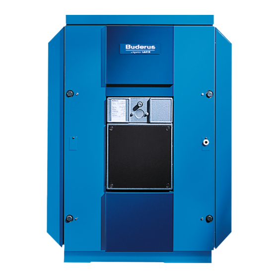
Logano G515
Boilers for oil/gas-fired power burners
Read carefully prior to installation and maintenance.
WARNING: If installation, adjustment, modification,
operation or maintenance of the heating system is carried
out by an unqualified person, this may result in personal
injury or property damage.
The directions of this installation manual must be followed
precisely.
If support or additional information is required, contact a
qualified service company, service provider or the gas
company.
WARNING:
Observe the safety instructions of this installation manual
before placing the heating appliance in operation.
The operating manual is a component of the technical
documentation and must be handed over to the operator
of the heating system. Explain to the owner or operator
how to use the heating system using the operating instruc-
tions. Make sure that he has been familiarized with all
information required for the operation of the heating sys-
tem..
NOTICE: If the storage tank will be installed in Massachu-
setts, it must be installed by an installer or dealer who is
registered there.
This manual is available in the English and French lan-
guage.
6 720 642 624-00.1O
Please keep this manual for future reference.
Low-temperature
oil/gas boiler
Advertisement
Table of Contents

Related Manuals for Buderus Logano G515


Summary of Contents for Buderus Logano G515
- Page 1 This manual is available in the English and French lan- guage. 6 720 642 624-00.1O Please keep this manual for future reference. Installation and Service Instructions Logano G515 Boilers for oil/gas-fired power burners Read carefully prior to installation and maintenance.
-
Page 2: Table Of Contents
Logano G515 – Delivery as a pre-assembled block . . 10 Logano G515 – Delivery in loose sections ..10 Transporting the boiler ....... 10 Positioning the boiler . -
Page 3: Guideline To Symbols And Safety Instructions
Appendix ......... . . 65 Logano G515 – 6 720 647 208 (2014/09) -
Page 4: Safety Instructions
▶ Only employ a trained and certified contractor to carry out work on the gas train. Explosive and easily combustible materials Never use or store easily combustible materials (paper, thinners, paints, etc.) near the appliance. Logano G515 – 6 720 647 208 (2014/09) -
Page 5: Product Description
Natural gas (NG) Remarks The Logano G515 boiler can be operated with the specified fuels. Select a burner suitable for use with the fuels specified for the Logano G515 boiler. The output figures shown in the Tab. “Technical Data” are nominal power figures. -
Page 6: Designated Use
Return water is preheated and mixed within the boiler before it comes in contact with the heating surface of the combustion chamber. The Logano G515 can be operated with oil, gas, and combination The Thermostream technology ensures there is an even temperature burners. -
Page 7: Additional Regulations For Installations In The Commonwealth Of Massachusetts
• APPROVED CARBON MONOXIDE DETECTORS. Each carbon monoxide detector as required in accordance with the above provisions shall comply with NPA 720 and be ANSI/UL 2034 listed and IAS certified. Logano G515 – 6 720 647 208 (2014/09) -
Page 8: Specifications
10" (270 mm) (250 mm) 6 720 642 623-01.1o Fig. 3 Technical data for Logano G515 (dimensions in inches (mm)) [EL] Drain valve (Rp ¾) ] Boiler heat exchanger length Overall boiler length [RK] Return connection on the boiler [VK] Supply connection on the boiler 1) With the drain valve (EL), you may only drain the system, not fill it. - Page 9 Required draft (Pa) Flue gas resistance – – – – – – (mbar) (0.5 – 0.6) (1.0 – 1.4) (1.1 – 1.6) (2.1 – 2.9) (2.5 – 3.3) (2.4 – 3.1) Table 4 Logano G515 – 6 720 647 208 (2014/09)
-
Page 10: Scope Of Delivery
Example: Safety limit (STB): = 212 °F (100 °C), max. possible supply temperature = 212–32 = 180 °F (100–18 = 82 °C). Scope of delivery Transporting the boiler The Logano G515 can be delivered either as a pre-assembled block or in Use suitable equipment to transport the individual boiler sections loose sections. -
Page 11: Positioning The Boiler
Positioning the boiler Positioning the boiler Boiler Assembly tool(s) Extension piece Length (total) in This chapter describes how to properly position the Logano G515. sections per boiler hub per boiler hub inches (mm) NOTICE: Risk of system damage from freezing. -
Page 12: Recommended Wall Clearances
Alternatively 80 – 5/16 (2040) 73 – 5/8 (1870) shorter cleaning devices or wet cleaning may be used. 87 (2210) 80 – 5/16 (2040) Table 10 Logano G515 – 6 720 647 208 (2014/09) -
Page 13: Boiler Block Assembly
For the further installation of a pre-assembled boiler block, see Chapter 7.3, page 18. Logano G515 – 6 720 647 208 (2014/09) -
Page 14: Joining The Boiler Block Assembly (Delivery As Loose Sections)
▶ Ensure adequate ventilation of the installation area. ▶ Please note the handling and safety instructions of the product used. ▶ Evenly coat the hub sealing faces with sealant. 6 720 642 623-09.1o Fig. 11 Fastening the installation aid Logano G515 – 6 720 647 208 (2014/09) - Page 15 Fig. 14 Driving nipples home The packing grooves ( Fig. 15, [1]) must be clean and dry to enable the sealant rope to adhere properly. ▶ Coat the packing grooves with adhesive (primer) Logano G515 – 6 720 647 208 (2014/09)
- Page 16 ▶ Never work directly in front of the assembly tool while it is being tensioned. ▶ Ensure that no one is standing in front of the assembly tool. 6 720 642 621-11.1o Fig. 18 Pound intermediate section in place Logano G515 – 6 720 647 208 (2014/09)
- Page 17 The boiler section has been equipped with foot wedges for ease of installation ( Fig. 21, [1]). The boiler section foot wedges are also used later for final leveling of the boiler block. Logano G515 – 6 720 647 208 (2014/09)
-
Page 18: Setting Up The Boiler Block - (Assembled Block)
The following pages describe the installation of the supply pipe and 720 42 23-23.1o sensor well. You must do both irrespective of whether the boiler is supplied pre-assembled or in separate sections. Fig. 25 Fitting the sensor well Logano G515 – 6 720 647 208 (2014/09) -
Page 19: Leak Test
▶ Separate the boiler at the leak location by driving (knocking) in flat wedges or chisels between the sections at the points provided at the top and bottom ( Fig. 27, [1 and 2], between the sections). Logano G515 – 6 720 647 208 (2014/09) -
Page 20: Boiler Water Connections
▶ When the heating system is in operation, do not fill it 720 42 23-28.1o via the boiler fill & drain valve. Instead, use the fill Fig. 30 Fitting the cleanout cover valve on the system side. Logano G515 – 6 720 647 208 (2014/09) -
Page 21: Fitting The Burner Door
Make sure the run-on slopes of the locking brackets are on the inside of the boiler. 720 42 23-31.1o ▶ Hook the burner door with the hinge lobes into the hinge pins. Fig. 33 Position of hot gas check plates Logano G515 – 6 720 647 208 (2014/09) -
Page 22: Insert The Flue Gas Baffle Plates
16 – 47/64 (425) top right top left bottom right bottom left – – Table 11 720 42 23-34.1o Fig. 36 Installing the mounting brackets Logano G515 – 6 720 647 208 (2014/09) -
Page 23: Fitting The Profile Rails
▶ Place the longitudinal rails ( Fig. 38, [1 and 2]) on both brackets on the rear and front section. ▶ Push longitudinal rails with pre-fitted screws ( Fig. 38, [3]) into the notches in the brackets ( Fig. 38, [4]) and screw together. Logano G515 – 6 720 647 208 (2014/09) -
Page 24: Fitting The Thermal Insulation
▶ Push the thermal insulation under the boiler block in the lower section. The boiler feet are placed in the cut-outs in the thermal insulation. 720 42 23-39.1o Fig. 41 Boiler block with thermal insulation Logano G515 – 6 720 647 208 (2014/09) - Page 25 21 – 1/2" (545 mm) 11,H 51 – 3/8" (1305 mm) 11,V 21 – 1/2" (545 mm) 12,H 58" (1475 mm) 12,V Front (boiler front) 720 42 23-41.1o Fig. 43 Fitting the lower crosswise profile rails Logano G515 – 6 720 647 208 (2014/09)
- Page 26 ▶ Attach the thermal insulation for the rear section via the four spring hooks to the boiler block thermal insulation. ▶ Close the slot below the flue outlet with a spring hook ( Fig. 46, [3]). Logano G515 – 6 720 647 208 (2014/09)
-
Page 27: Fitting Side Panels And Top Covers
10 boiler sections 11 boiler sections 12 boiler sections Flap 4 – 21/64" (110 mm) ] 24 – 7/32" (615 mm) ] 27 – 9/16" (700 mm) ] 13 – 25/64" (340 mm) Logano G515 – 6 720 647 208 (2014/09) - Page 28 ( Chapter 9, page 32). ▶ Once the side panels ( Fig. 51 [2]) have been vertically aligned, the self-tapping screws in the base rail ( Fig. 51, [4]) must be tightened. Logano G515 – 6 720 647 208 (2014/09)
- Page 29 ▶ Push upper rear boiler panel under the rear boiler cover ( Fig. 55, [1]) and screw to the side panels from the back using four self- tapping screws ( Fig. 55, [2]). 720 42 23-54.1o Fig. 56 Installing the rear boiler panel sections Logano G515 – 6 720 647 208 (2014/09)
- Page 30 Fig. 57 Installing the burner door cladding ▶ Attach the burner door panels to the burner door cladding ( Fig. 58, [1 and 2]). 720 42 23-5 .1o Fig. 58 Attaching the burner door panels Logano G515 – 6 720 647 208 (2014/09)
-
Page 31: Connecting The Boiler On The Flue Gas Side
Vent pipe sealing collar Flue gas temperature sensor Sleeve Vent pipe Hose clamps Exhaust manifold 2 × Vent pipe diameter, at least 28 – 22/64 inches (720 mm) Retighten the hose clamps if required. Logano G515 – 6 720 647 208 (2014/09) -
Page 32: Installing The Control Panel
(Logamatic 33xx) or remove the rear panel section (Logamatic 43xx) ( Fig. 61, [2]). ▶ Route the capillaries through the cable entry and unroll to the required length. Logano G515 – 6 720 647 208 (2014/09) - Page 33 ( Fig. 61, [2]). ▶ Put the top cover in place ( Fig. 60, [1]) and tighten the screws ( Fig. 65). Logano G515 – 6 720 647 208 (2014/09)
-
Page 34: Mounting The Burner
Fig. 66, [4]) using the appropriate insulating rings ( Fig. 66, [3]). ▶ Connect the vent connection to the burner to ensure the inspection window remains free of deposits. 6 720 642 623-63.1o Fig. 66 Mounting the burner Logano G515 – 6 720 647 208 (2014/09) -
Page 35: System Start-Up
Filling the system System start-up NOTICE: Risk of system damage from temperature You can connect control panels of the 4000 series to the Logano G515. stresses. The commissioning process for the different types of control panel is the ▶ During operation, only fill the heating system via the same. -
Page 36: Raising Flue Gas Temperature
720 42 23- 5.1o Fig. 68 Position of hot gas check plates Logano G515 – 6 720 647 208 (2014/09) -
Page 37: Commissioning Log
11.6 Commissioning log The Logano G515 can be used with an oil or gas-fired burner. Fill in the ▶ Sign all start-up work as completed and enter the relevant date. commissioning log for the appropriate type of oil or gas burner carefully. -
Page 38: Shutting Down The System
Shutting down the system Shutting down the system You can connect control panels of the 4000 series to the Logano G515. The shutting down process for the different types of control panel is the same. NOTICE: Risk of system damage from freezing. -
Page 39: System Inspection And Maintenance
▶ Shut off the fuel supply to the burner. ▶ De-energize the system. 720 42 23- 8.1o Fig. 72 Flue gas baffles, removing The various brush types available from Buderus (accessories) are shown 6 720 642 623-73.1O in Fig. 73. Fig. 70 Logamatic 4311 shown as an example ▶... - Page 40 1 and 2 ( Fig. 74, [1 and 3]). ▶ Clean the rear wall of the combustion chamber with cleaning brush 3. You can obtain sealant ropes from your local Buderus ▶ Clean the rest of the combustion chamber ( Fig. 74, [2]) with wholesaler.
-
Page 41: Wet-Cleaning The Boiler
▶ If the operating pressure drops below 15 psi (1 bar), fill boiler water. ▶ Ensure that your heating system is bled. ▶ Check the heating system for leaks and the function of the expansion vessel. 7 747 019 141-17.1RS Fig. 77 Pressure/temperature gauge Logano G515 – 6 720 647 208 (2014/09) -
Page 42: Inspection And Maintenance Logs
If during inspection work conditions are identified that require additional service and maintenance, perform this work on an as-needed basis. If make-up water is added, the quality of this water must correspond to the specifications in the enclosed operating manual. Logano G515 – 6 720 647 208 (2014/09) - Page 43 System inspection and maintenance Date:____________ Date:____________ Date:____________ Date:____________ Company stamp/signature Company stamp/signature Company stamp/signature Company stamp/signature Logano G515 – 6 720 647 208 (2014/09)
- Page 44 Record the final checks of the maintenance work, incl. measurements and test results Check safe and proper operation Confirm professional inspection Company stamp/signature Company stamp/signature Date:____________ Date:____________ Date:____________ Date:____________ Company stamp/signature Company stamp/signature Company stamp/signature Company stamp/signature Logano G515 – 6 720 647 208 (2014/09)
-
Page 45: Troubleshooting Burner Faults
If the burner does not restart after three attempts, refer to the technical documentation provided with the burner to find out how to reset it. Logano G515 – 6 720 647 208 (2014/09) -
Page 46: Spare Parts
Page 58 Group 6 – pedestal - silencer Page 60 Group 7 – burner cover Page 62 Group 8 – safety group Table 14 Spare part groups Logano G515 Logano G515 – 6 720 647 208 (2014/09) - Page 47 Spare Parts View "A" Ansicht "A" M12x40 M12x40 View "A" turned 90° Ansicht "A" 90 gedreht M12x40 6720906654.aa.RS-Kesselblock-hinten G515 Fig. 79 Group 1 – boiler block - front Logano G515 Logano G515 – 6 720 647 208 (2014/09)
- Page 48 Flue gas baffle bottom right 680mm 5 265 218 Sealant rope 18x2900mm long 63 020 973 Flange cover square 110mm 5 428 081 Table 15 Group 1 – boiler block - front Logano G515 Logano G515 – 6 720 647 208 (2014/09)
- Page 49 Fittings G515 11-pc loose spare 5 621 608 Fittings G515 12-pc loose spare 5 621 610 Sealant rope 18x3800 GP 63 020 975 Table 15 Group 1 – boiler block - front Logano G515 Logano G515 – 6 720 647 208 (2014/09)
- Page 50 Spare Parts View "A" Ansicht "A" M12x40 M12x40 View "A" turned 90° Ansicht "A" 90 gedreht M12x40 6720906654.aa.RS-Kesselblock-hinten G515 Fig. 80 Group 2 – boiler block - back Logano G515 Logano G515 – 6 720 647 208 (2014/09)
- Page 51 2 037 038 Sealing compound brown 63 014 361 Installation materialG515 VE 5 015 940 Maintenance package G515 63 006 596 Table 16 Group 2 – boiler block - back Logano G515 Logano G515 – 6 720 647 208 (2014/09)
- Page 52 Spare Parts ST6,3x25 M12x40 6720906655.aa.RS-Brennertür G51 Fig. 81 Group 3 – burner door Logano G515 Logano G515 – 6 720 647 208 (2014/09)
- Page 53 8 718 575 500 0 Burner plate blind 10x320x320mm 5 431 165 Hex-head bolt M16x140 (DIN931), black 80 080 136 Sealing compound brown 63 014 361 Table 17 Group 3 – burner door Logano G515 Logano G515 – 6 720 647 208 (2014/09)
- Page 54 Spare Parts M8x20 M8x20 6720906656.aa.RS-Verkleidung-Befestigung G515 Fig. 82 Group 4 – jacket - fastening Logano G515 Logano G515 – 6 720 647 208 (2014/09)
- Page 55 Top cross member G515 5 078 624 Base cross cpl G515 5 078 698 Flat-head screw ST3.9x9.5 A3T (10x) 7 747 026 999 Table 18 Group 4 – jacket - fastening Logano G515 Logano G515 – 6 720 647 208 (2014/09)
- Page 56 10 11 12 Glieder / segments 10 11 Pos. Pos. 614mm 509mm 699mm 339mm 339mm M6x12 28 4 M6x12 6720906657.aa.RS-Verkleidung-Blechteile G515 M6x12 Fig. 83 Group 5 – jacket - sheetmetal parts Logano G515 Logano G515 – 6 720 647 208 (2014/09)
- Page 57 Flat-head screw ST3.9x9.5 A3T (10x) 7 747 026 999 Snap nut 4.8-A3KSNU5743 5 834 364 Installation material G515 5 078 716 Table 19 Group 5 – jacket - sheetmetal parts Logano G515 Logano G515 – 6 720 647 208 (2014/09)
- Page 58 Spare Parts 6720906658.aa.RS-Untergestell G515 Fig. 84 Group 6 – pedestal - silencer Logano G515 Logano G515 – 6 720 647 208 (2014/09)
- Page 59 Vent pipe silencer, steel, DN 250 5 074 550 Sealant rope 10x2000 GP 63 020 963 Vent pipe sealing collar DN250 5 354 038 Table 20 Group 6 – pedestal - silencer Logano G515 Logano G515 – 6 720 647 208 (2014/09)
- Page 60 Spare Parts M6x12 M6x12 6720906659.aa.RS-Schalldämpfer G515 Fig. 85 Group 7 – burner cover Logano G515 Logano G515 – 6 720 647 208 (2014/09)
- Page 61 5 928 156 Swivel roller A2K/75 5 755 055 Installation material burner sound-damping cover 5 158 222 Moltoprene knob plate 50x1000x2000mm 5 678 100 Table 21 Group 7 – burner cover Logano G515 Logano G515 – 6 720 647 208 (2014/09)
- Page 62 Spare Parts 6720906660.aa.RS-Sicherheitsgruppe G515 Fig. 86 Group 8 – safety group Logano G515 Logano G515 – 6 720 647 208 (2014/09)
- Page 63 Water level limiter SYR 933, 20, 11 8 718 575 403 0 Gasket set KSG 5 639 634 Seal DIN2690 DN65 2 mm 81 363 040 Table 22 Group 8 – safety group Logano G515 Logano G515 – 6 720 647 208 (2014/09)
-
Page 64: Index
Heat exchanger baffle plates ..........Hot gas check plates ..........Inspection contract ............... Jacket ......Maintenance contract (as-required basis) ............Nominal output ........... Operating pressure ........Operating pressure, maximum ..........Overall boiler length Logano G515 – 6 720 647 208 (2014/09) -
Page 65: Appendix
Manufacturer no. ______________________ Location ______________________ The technical documentation has been handed over to the user. He has been familiarized with the safety instructions, operation and maintenance of the system. Date, signature (user) Logano G515 – 6 720 647 208 (2014/09) - Page 66 Appendix Logano G515 – 6 720 647 208 (2014/09)
- Page 67 Appendix Logano G515 – 6 720 647 208 (2014/09)