Table of Contents
Advertisement
Quick Links
CDM-Qx
Multi-Channel Satellite Modem with DoubleTalk™
Carrier-in-Carrier
®
Installation and Operation Manual
.
Note: This manual incorporates data for the CDM-Qx and CDM-QxL
IMPORTANT NOTE: The information contained in this document supersedes all previously published
information regarding this product. Product specifications are subject to change without prior notice.
Part Number MN/CDMQX.IOM
Revision 6
Advertisement
Table of Contents

Related Manuals for Comtech EF Data CDM-Qx


Summary of Contents for Comtech EF Data CDM-Qx
-
Page 1: Installation And Operation Manual
® Installation and Operation Manual Note: This manual incorporates data for the CDM-Qx and CDM-QxL IMPORTANT NOTE: The information contained in this document supersedes all previously published information regarding this product. Product specifications are subject to change without prior notice. - Page 3 Comtech EF Data is an ISO 9001 Part Number MN/CDMQx.IOM Registered Company Revision 6 June 12, 2007 Copyright © Comtech EF Data, 2007. All rights reserved. Printed in the USA. Comtech EF Data, 2114 West 7th Street, Tempe, Arizona 85281 USA, 480.333.2200, FAX: 480.333.2161...
- Page 4 This page is intentionally blank.
-
Page 5: Table Of Contents
CDM-Qx Satellite Modem Revision 6 Table of Contents MN/CDMQx.IOM Table of Contents PREFACE........................... XI Customer Support ........................xi About this Manual........................xii Reporting Comments or Suggestions Concerning this Manual ..........xii Conventions and References ....................xii Metric Conversion ........................xii Cautions and Warnings......................xii Electrical Safety ........................xiii... - Page 6 CDM-Qx Satellite Modem Revision 6 Table of Contents MN/CDMQx.IOM FAST Options and Hardware Options ...............1–4 1.4.1 FAST Accessible Options..................1–5 1.4.2 FAST System Theory ....................1–5 1.4.3 Implementation......................1–6 1.4.4 Hardware Options ....................1–6 1.4.5 Supporting Hardware and Software ..............1–6 L-Band..........................1–7 Compatibility .......................1–7 CHAPTER 2.
- Page 7 CDM-Qx Satellite Modem Revision 6 Table of Contents MN/CDMQx.IOM AC Power Connector ....................4–14 DC Power Connector ....................4–14 Ground Connector ....................4–14 CHAPTER 5. FRONT PANEL OPERATION...............5–1 Introduction .........................5–1 Keypad .........................5–3 Left-Hand Display Area....................5–3 5.3.1 Modems.........................5–4 5.3.2 Redundancy ......................5–4 5.3.3 Spectrum Analyzer ....................5–5 Right-Hand Display Area ....................5–5...
- Page 8 CDM-Qx Satellite Modem Revision 6 Table of Contents MN/CDMQx.IOM 5.7.4.4 (Info!Buffer) - BUFFER INFORMATION............5–56 5.7.4.5 (Info!Frame) – FRAMING AND EDMAC INFORMATION ......5–56 5.7.4.6 (Info!Interface) – INTERFACE INFORMATION ..........5–57 5.7.4.7 (Info!Mask) – ALARM MASK INFORMATION..........5–57 5.7.4.8 (Info!Ref) - FREQUENCY REFERENCE ............5–57 5.7.4.9...
- Page 9 CDM-Qx Satellite Modem Revision 6 Table of Contents MN/CDMQx.IOM Setting AUPC Parameters ..................8–2 8.2.1 Target Eb/No ......................8–2 8.2.2 Max Range ......................8–2 8.2.3 Alarm ........................8–3 8.2.4 Demod Unlock.......................8–3 Compensation Rate ....................8–3 Monitoring........................8–4 ® CHAPTER 9. DOUBLETALK™ CARRIER-IN-CARRIER OPERATION ......9–1 CHAPTER 10.
- Page 10 CDM-Qx Satellite Modem Revision 6 Table of Contents MN/CDMQx.IOM APPENDIX B. FLASH UPGRADING ................. B–1 Ethernet FTP upload procedure: ................B–1 APPENDIX C. REMOTE CONTROL................... C-1 RS-485 .......................... C-1 RS-232 .......................... C-2 Basic Protocol ......................C-2 Packet Structure......................C-3 C.4.1 Start Of Packet ......................
- Page 11 Table 6-5. Turbo Product Coding processing delay comparison ..........6–6 Table 6-6. Turbo Product Coding Summary ................6–8 Table 11-1. Web Server Menu Tree ..................11–3 Figures Figure 1-1. CDM-Qx/QxL ......................1–1 Figure 2-1. Installation of the Optional Rear-Mounting Support Brackets.........2–3 Figure 3-1. Modem Functional Block Diagram................3–3 Figure 4-1. Front Panel ......................4–1 Figure 4-2.
- Page 12 Figure 6-3. 8-PSK/TCM Rate 2/3 with and without concatenated R-S Outer Code....6–11 Figure 6-4. Comtech EF Data Turbo Product Codec Rate 3/4 QPSK, 8-PSK and 16-QAM ..6–12 Figure 6-5. Comtech EF Data Turbo Product Codec Rate 7/8 QPSK, 8-PSK and 16-QAM ..6–13 Figure 6-6.
-
Page 13: Preface
480.333.2200 (Main Comtech EF Data number) 480.333.4357 (Customer Support Desk) 480.333.2161 FAX To return a Comtech EF Data product (in-warranty and out-of-warranty) for repair or replacement: • the Comtech EF Data Customer Support Department. Be prepared to supply the Contact Customer Support representative with the model number, serial number, and a description of the problem. -
Page 14: About This Manual
For information regarding this product’s warranty policy, refer to the Warranty Policy, p. xv. About this Manual This manual provides installation and operation information for the Comtech EF Data CDM-Qx Multi-Channel Modem with DoubleTalk™ Carrier-in-Carrier®. This is a technical document intended for earth station engineers, technicians, and operators responsible for the operation and maintenance of the CDM-Qx. -
Page 15: Electrical Safety
EN 60950: Safety of Information Technology Equipment, including electrical business machines The CDM-Qx 70/140 is rated for operation over the range 100 to 240 VAC. It has a maximum power consumption of 120 watts, and draws a maximum of 1 amp. -
Page 16: Telecommunications Terminal Equipment Directive
The equipment is not designed for connection to power system that has no direct connection to ground. The CDM-Qx is shipped with a line inlet cable suitable for use in the country of operation. If it is necessary to replace this cable, ensure the replacement has an equivalent specification. Examples of acceptable ratings for the cable include HAR, BASEC and HOXXX-X. -
Page 17: Warranty Policy
Comtech EF Data will return the equipment by the same method (i.e., Air, Express, Surface) as the equipment was sent to Comtech EF Data. -
Page 18: Exclusive Remedies
The remedies provided herein are the buyer’s sole and exclusive remedies. Comtech EF Data shall not be liable for any direct, indirect, special, incidental, or consequential damages, whether based on contract, tort, or any other legal theory. -
Page 19: Chapter 1. Introduction
Chapter 1. INTRODUCTION Introduction ® The CDM-Qx, Multi-Channel Satellite Modem with DoubleTalk™ Carrier-in-Carrier a 70/140 MHz (or CDM-QxL with 950MHz-1950MHz L-Band operation) modular multi-channel modem with redundancy contained in a single rack unit (1RU) chassis. The Modem offers flexibility, redundancy, integration, and performance with four slots configurable as modulators or demodulators. -
Page 20: Features
DoubleTalk™ Carrier-in-Carrier allowing Tx and Rx carriers of a full-duplex link to use the same transponder segment • CDM-Qx: 50 to 90 and 100 to 180 MHz frequency range • CDM-QxL: 950 MHz-1950 MHz L-band • 32 kbps to 20 Mbps •... -
Page 21: Software - Flash Upgrading
CDM-Qx Satellite Modem Revision 6 Introduction MN/CDMQx.IOM 1.2.2 Software – Flash Upgrading The internal software is both powerful and flexible, permitting storage and retrieval of up to 10 different modem configurations. The modem uses ‘flash memory’ technology internally, and new firmware can be uploaded to the unit from an external PC. This simplifies software upgrading, and updates can now be sent via the Internet, e-mail, or on disk. -
Page 22: Remote Control
Modem may be purchased with only the desired modules and features enabled. If, at a later date, a customer wishes to upgrade the functionality of a modulator or demodulator, Comtech EF Data provides a system known as FAST (Fully Accessible System Topology) which permits the purchase and installation of options through the use of special authorization codes entered through the front panel, or remotely. -
Page 23: Fast Accessible Options
These techniques allow the use of a unique access code to enable configuration of the available hardware. The access code can be purchased at any time from Comtech EF Data. Once obtained, the access code is loaded into the unit through the front panel keyboard or the rear remote port. -
Page 24: Implementation
Hardware Options There are four hardware options available. There is the Comtech EF Data Turbo Product Codec (TPC), representing a very significant development in the area of FEC. It consists of a plug-in daughter card (SIMM module) that is field upgradeable. The TPC option provides data rate capability up to 20 Mbps, and code rates of: •... -
Page 25: L-Band
Compatibility The Modem is backwards compatible with a number of Comtech EF Data CDM modems, SDM modems, and SLM modems. 1–7... - Page 26 CDM-Qx Satellite Modem Revision 6 Introduction MN/CDMQx.IOM Notes: 1–8...
-
Page 27: Chapter 2. Installation
Chapter 2. INSTALLATION Unpacking Inspect shipping containers for damage. If shipping containers are damaged, keep them until the contents of the shipment have been carefully inspected and checked for normal operation. The modem and manual are packaged in pre-formed, reusable, cardboard cartons containing foam spacing for maximum shipping protection. -
Page 28: Mounting
The tools required for this installation are a medium Phillips™ screwdriver and a 5/32-inch SAE Allen™ Wrench. The mounting kit is assembled onto the CDM-Qx and into the equipment rack as illustrated in Figure 2-1 and per the following procedure:... -
Page 29: Configuration
CDM-Qx Satellite Modem Revision 6 Installation MN/CDMQx.IOM Equipment Rack Rear Mounting Rail #10 Shoulder Screw Support Bracket #10 Flat Washer #10 Flat Washer #10 Bracket Bolt #10 Split Washer #10 Hex Nut Back of unit Figure 2-1. Installation of the Optional Rear-Mounting Support Brackets Configuration There are no internal jumpers to configure. -
Page 30: Select Internal If Loop
CDM-Qx Satellite Modem Revision 6 Installation MN/CDMQx.IOM Select Internal IF Loop Correct operation of the unit may be verified rapidly, without the need for externally connected equipment, providing there are at least one modulator and one demodulator: From the top-level menu, select... -
Page 31: Chapter 3. Functional Description
Chapter 3. FUNCTIONAL DESCRIPTION The modem has two fundamentally different types of interface – IF and Data: • The Data interface can be a bi-directional path, which connects with the customer’s equipment (assumed to be the DTE) and the modem (assumed to be the DCE). - Page 32 CDM-Qx Satellite Modem Revision 6 Functional Description MN/CDMQx.IOM is enabled) where the overhead information is removed. Following this, the data passes to the Plesiochronous/Doppler buffer, which has a programmable size, or alternatively bypasses the buffer. From here, the receive clock and data signals are routed to the terrestrial interface, and are passed to the externally connected DTE equipment.
-
Page 33: Figure 3-1. Modem Functional Block Diagram
CDM-Qx Satellite Modem Revision 6 Functional Description MN/CDMQx.IOM Figure 3-1. Modem Functional Block Diagram 3–3... - Page 34 CDM-Qx Satellite Modem Revision 6 Functional Description MN/CDMQx.IOM Notes: _______________________________________ _______________________________________ _______________________________________ _______________________________________ _______________________________________ _______________________________________ _______________________________________ _______________________________________ _______________________________________ _______________________________________ _______________________________________ _______________________________________ _______________________________________ _______________________________________ _______________________________________ _______________________________________ _______________________________________ _______________________________________ _______________________________________ _______________________________________ _______________________________________ _______________________________________ _______________________________________ _______________________________________ _______________________________________ _______________________________________ 3–4...
-
Page 35: Chapter 4. External Connections
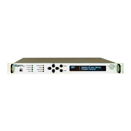
Current Version – as of June 2007 Figure 4-1. Front Panel (Earlier and Current Versions) The CDM-Qx front panel features a Vacuum Fluorescent Display (VFD), a keypad, and eight LED indicators. The user enters data via the keypad, and messages are displayed on the VFD. - Page 36 The keypad has six individual keyswitches. They have a positive ‘click’ action, which provides the user with tactile feedback. As shown in Figure 4-1, versions of the CDM-Qx manufactured prior to June 2007 feature a keypad mounted directly behind a fully sealed membrane overlay.
-
Page 37: Rear Panel
CDM-Qx Satellite Modem Revision 6 External Connections MN/CDMQx.IOM Rear Panel The rear panel can be customized to meet the customer’s requirements. Figure 4-2 shows three configurations that are available. Table 4-1 lists their connectors and Figure 4-2 shows the locations. -
Page 38: Table 4-1. Modem Rear Panel Connectors
CDM-Qx Satellite Modem Revision 6 External Connections MN/CDMQx.IOM 5. In the example Configuration #1 above, because all modules have interfaces, the following configurations are possible: a. Two independent modulators - one with a G.703 balanced and the other with an EIA-530 interface, with two independent demodulators one with a G.703 balanced and the other... - Page 39 CDM-Qx Satellite Modem Revision 6 External Connections MN/CDMQx.IOM Name Ref. Desig. Connector Type Function Slot #2 Demod: Alarms 15-Pin Male Form-C Alarms G.703 Unbalanced G.703 Data input Slot #3 Mod: Alarms 15-Pin Male Form-C Alarms EIA-530 25-Pin Female Data Input...
-
Page 40: Chassis Connections
CDM-Qx Satellite Modem Revision 6 External Connections MN/CDMQx.IOM Chassis Connections 4.4.1 USB Port This port is used to reflash firmware. 4.4.2 M&C 10/100BaseT Connector The M&C 10/100BaseT connector is an 8-pin RJ-45 10/100BaseT Ethernet port providing access to the modem’s management functions. -
Page 41: 4.4.4 Alarms Connector
CDM-Qx Satellite Modem Revision 6 External Connections MN/CDMQx.IOM 4.4.4 Alarms Connector All modules contain an alarm connector. The Alarms connector is a 15-pin 'D' type male (DB15-M). This provides the user with access to the Form-C relay contacts, which indicate the fault status of the unit. -
Page 42: 4.4.5 Balanced G.703 Connector Tx/Rx Connector
CDM-Qx Satellite Modem Revision 6 External Connections MN/CDMQx.IOM 4.4.5 Balanced G.703 Connector Tx/Rx Connector The Balanced G.703 connection is a 15-pin female connector located on the rear mounting plate of the modulator or demodulator. If a Modulator and Demodulator are vertically grouped together as a modem, the data interface connector on the Demodulator switches to duplex. -
Page 43: 4.4.7 Rs-530 Data Interface Connector
CDM-Qx Satellite Modem Revision 6 External Connections MN/CDMQx.IOM 4.4.7 RS-530 Data Interface Connector The Data connector is a 25-pin ‘D’ type female (DB-25F). This connector conforms to the RS-530 pinout, which allows for connection of different electrical standards, including EIA-422, V.35, and EIA-232. -
Page 44: 4.4.8 Quad E1 Data Interface Connectors
CDM-Qx Satellite Modem Revision 6 External Connections MN/CDMQx.IOM 4.4.8 Quad E1 Data Interface Connectors The Quad E1 Data interface card allows the user to connect 1 to 4 different terrestrial E1 ports. Each port can be independently configured for full E1, (framed or unframed E1 data), or fractional E1, (with D&I). -
Page 45: 4.4.9 Tx And Rx If Connectors
Modulator and Demodulator. When the CDM-Qx is configured as a modem, only the Demodulator is required to have a HSSI Interface and the Modulator is assigned a blank panel with Alarm output only. -
Page 46: General Specifications
CDM-Qx Satellite Modem Revision 6 External Connections MN/CDMQx.IOM Tx Clock Input (External) Tx Data Processor Processor Mux / Mux / Output Clock (Rate Programmable) Demux & Demux Data Modem (RTS) Interface μC Buffer Buffer (CTS) Interface Interface Loopback Loopback Control... -
Page 47: Connector Pinout
CDM-Qx Satellite Modem Revision 6 External Connections MN/CDMQx.IOM Item Requirement Operation Simplex (Tx only or Rx only) or full duplex Signal Sense Programmable Normal or Inverted or TT and TD, RT and RD Cable Length to 20 Mbps 2 M (6 ft) nominal, up to 15 M (49 ft) maximum – note higher data rates usually require shorter cable lengths 4.4.10.2... -
Page 48: Ac Power Connector
CDM-Qx Satellite Modem Revision 6 External Connections MN/CDMQx.IOM AC Power Connector A standard, detachable, non-locking, 3-prong power cord (IEC plug) supplies the Alternating Current (AC) power to the modem. Observe the following: AC Power Specifications Input Power 290W maximum, 110W typical without BUC power supply. -
Page 49: Chapter 5. Front Panel Operation
Chapter 5. FRONT PANEL OPERATION Introduction Keypad Left-Hand Right-Hand Display Area Display Area Figure 5-1. Front Panel Operation The user can fully control and monitor the operation of the Modem from the front panel (Figure 5-1), using the keypad and display. Nested menus are used, which display all available options, and prompt the user to carry out a required action. -
Page 50: Table 5-1. Front Panel Led Indicators
CDM-Qx Satellite Modem Revision 6 Front Panel Operation MN/CDMQx.IOM this solid block cursor would obscure the item being edited (for example, a numeric field) the cursor automatically changes to an underline cursor. If the user were to display the same screen for weeks at a time, the display could become ‘burnt’... -
Page 51: Keypad
CDM-Qx Satellite Modem Revision 6 Front Panel Operation MN/CDMQx.IOM Keypad The keypad is shown in Figure 5-2: Diamond Keypad (used prior to June 2007) Button Keypad (used as of June 2007) Figure 5-2. Keypad The function of these keys is as follows:... -
Page 52: Modems
CDM-Qx Satellite Modem Revision 6 Front Panel Operation MN/CDMQx.IOM from the back of the chassis. The left hand TX on the display corresponds with the top left slot in the chassis when viewed from the back. An empty slot is left blank. -
Page 53: Spectrum Analyzer
CDM-Qx Satellite Modem Revision 6 Front Panel Operation MN/CDMQx.IOM Three redundancy modes are possible with a modem. Back-up devices are notated with a B suffix. In a non-modem configuration, the back-up device must be installed in slot #4. If a backup device has failed, the B suffix and the F suffix will alternately display. -
Page 54: Accessing The Display Area
CDM-Qx Satellite Modem Revision 6 Front Panel Operation MN/CDMQx.IOM Table 5-2. Prinicpal Menu Tree Para. Title Remarks Opening Screen Main Menu Select: Config; Monitor; Test; Info; Save/Load; Util; ODU 5.7.1 Config: Select: Remote; Tx; Rx; Group; Frame; Interface; Ref; Mask; ODU Config →... -
Page 55: Opening Screen
CDM-Qx Satellite Modem Revision 6 Front Panel Operation MN/CDMQx.IOM Opening Screen Comtech EF Data CDM-Qx Firmware Version: 1.1.1 This screen is displayed whenever power is first applied to the unit (70/140 MHz version). For L-Band units, the word “ CDM-Qx ”... -
Page 56: Config
‘all ones’ as an idle pattern. However, by convention, the Mask ‘all ones’ condition is taken to be the Alarm Indication Signal (AIS). The CDM-Qx monitors for the AIS condition, and if desired, this alarm may be masked. (Outdoor Unit) This menu sub-branch permits the user to configure... -
Page 57: Config!Remote) - Remote Control
CDM-Qx Satellite Modem Revision 6 Front Panel Operation MN/CDMQx.IOM 5.7.1.1 (Config%Remote) – REMOTE CONTROL (◄ ►) Select Local, Serial, or Ethernet using the arrow keys, then press ENTER Remote Control Entry: Local Serial Ethernet (◄ ►,ENT) Selecting Local disables remote control. Remote monitoring is still possible. - Page 58 CDM-Qx Satellite Modem Revision 6 Front Panel Operation MN/CDMQx.IOM (Config%Remote%Serial%Baudrate) Selecting Baud Rate presents the user with the following menu: M&C Serial Bus Baud Rate: 19200 Baud (▲ ▼,ENT) Values of 2400, 4800, 9600, 19200, 38400, and 57600 baud are possible. Edit the baud rate of the remote control bus connected locally to the M&C computer.
-
Page 59: Snmp Communities
CDM-Qx Satellite Modem Revision 6 Front Panel Operation MN/CDMQx.IOM (Config%Remote%Ethernet%MAC) Selecting MAC presents the users with a read-only display, as shown in this example: M&C Port MAC Address: 00-06-B0-00-00-D5 This read-only window displays the factory program MAC address for the Ethernet management interface. - Page 60 CDM-Qx Satellite Modem Revision 6 Front Panel Operation MN/CDMQx.IOM (Config%Remote%Ethernet%SNMP%Traps) Selecting displays the following submenu Traps Traps: Community Version IP Addr#1 IP Addr#2 (◄ ►, ENT) Selecting Community displays the following submenu: Trap Community: (◄ ► ENT) ▲ ▼, comtech Edit the Trap Community string using the ◄...
-
Page 61: Config!Tx) - Transmit
CDM-Qx Satellite Modem Revision 6 Front Panel Operation MN/CDMQx.IOM 5.7.1.2 (Config%Tx) - TRANSMIT Tx: FEC Mod Code Data Freq On/Off Pwr Scram Clk Inv Txα α Select FEC, Mod, Code, Data, Freq, On/Off, Pwr, Scram, Clk, Inv, or Tx using the ◄... - Page 62 CDM-Qx Satellite Modem Revision 6 Front Panel Operation MN/CDMQx.IOM If the user changes a parameter within this hierarchy, the other parameters may become invalid. In this case, the software will change those other parameters, in order that the configuration remains valid at all times.
- Page 63 CDM-Qx Satellite Modem Revision 6 Front Panel Operation MN/CDMQx.IOM (Config%Tx%Code) – TX CODE RATE Tx Code Rate: 5/16 21/44 1/2 2/3 3/4 7/8 17/18 (◄ ►) All possible choices are presented at all times. If an option is not installed (either Hardware, or FAST) or valid, the ◄ ► arrow keys will force the cursor to skip past the unavailable choice.
- Page 64 CDM-Qx Satellite Modem Revision 6 Front Panel Operation MN/CDMQx.IOM FEC Type Modulation Code Rate Data Rate Range EDMAC limited? BPSK Rate 1/2 32 kbps to 5 Mbps Rate 1/2 32 kbps to 10 Mbps Viterbi Yes – see note below...
- Page 65 CDM-Qx Satellite Modem Revision 6 Front Panel Operation MN/CDMQx.IOM (Config%Tx%On/Off) – TRANSMIT ON/OFF CONTROL Tx Output State: RxTxInhibit Common (◄ ►, ENT) Select either On, Off, RxTxInhibit, or Common using the ! " arrow keys, then press ENTER. When Rx-Tx Inhibit (RTI) is selected, it prevents the TX carrier from being transmitted, until the demodulator is locked.
- Page 66 CDM-Qx Satellite Modem Revision 6 Front Panel Operation MN/CDMQx.IOM Selecting AUPC without ‘Framed’ mode selected results in the following display: Warning! AUPC needs Framed Mode (ENT or CLR) Pressing either returns the user to the previous menu with Manual ENTER CLEAR selected.
- Page 67 CDM-Qx Satellite Modem Revision 6 Front Panel Operation MN/CDMQx.IOM (Config%Tx%Pwr%AUPC) – DEMOD-UNLOCK Action when Remote Demod unlocks: Nom-Pwr Max-Pwr The choices are: Nom-Pwr (Nominal Power), where the output level will revert to the nominal power level set under Manual, or Max-Pwr (Maximum Power), where the output level will change to the maximum permitted.
- Page 68 Select Int (Internal), Ext (External) or Loop-Timed using the ◄ ► arrow keys, then press ENTER Indicates that the CDM-QX will supply a clock to the DTE, which is derived from Internal its internal high-stability source. Indicates that the CDM-QX expects to receive a clock from the DTE, to which the External unit can phase-lock its internal circuits.
-
Page 69: Config!Rx) - Receive
CDM-Qx Satellite Modem Revision 6 Front Panel Operation MN/CDMQx.IOM (Config%Tx%Txα) – TX Roll-Off (α) factor Tx Roll-off: 20% (◄ ►, ENT) The default is 35%. Select 20% or 35% using the ◄ ► arrow keys, then press ENTER 5.7.1.3 (Config%Rx) - RECEIVE... - Page 70 CDM-Qx Satellite Modem Revision 6 Front Panel Operation MN/CDMQx.IOM The FEC type takes the highest configuration priority, and the selection here depends on what, if any, optional plug-in Codecs are installed. The choice of FEC type then determines what demodulation types, code rates, and data rates are available.
- Page 71 CDM-Qx Satellite Modem Revision 6 Front Panel Operation MN/CDMQx.IOM (Config%Rx%Demod) – DEMODULATION SCHEME Demodulation: BPSK QPSK 8-PSK 16-QAM (◄ ► ENT) All possible choices are presented at all times. If an option is not installed (either Hardware, or FAST) or valid, the ◄ ► arrow keys will force the cursor to skip past the unavailable choice.
- Page 72 The range of frequencies depends upon the plug-in module – the preceeding example shows the L-Band version of the CDM-Qx. Edit the receive frequency by selecting the digit to be edited, using the !" arrow keys. The value of the digit is then changed using...
- Page 73 CDM-Qx Satellite Modem Revision 6 Front Panel Operation MN/CDMQx.IOM as shown below, to include the calculated Receive RF frequency of the modem/BUC combination: Rx IF Freq:1156.3456 MHz RF=12156.3456 (◄ ► ▲ ▼ ENT) As the Rx IF frequency is edited, the RF frequency will automatically be updated.
- Page 74 CDM-Qx Satellite Modem Revision 6 Front Panel Operation MN/CDMQx.IOM (Config%Rx%Buf) – RX BUFFER CLOCK SOURCE Rx Buffer: Internal Rx-Sat Tx-Terr Ins External (◄ ►, ENT) The user will select which Rx buffer clock source. Note that Tx-Terrestrial will only be selected if the cards are grouped as modem.
- Page 75 CDM-Qx Satellite Modem Revision 6 Front Panel Operation MN/CDMQx.IOM (Config%Rx%Inv) – RX INVERSION FUNCTIONS Select Spectrum, Data, or Clock using the ◄ ► arrow keys, then press ENTER Rx Inversion functions: Spectrum Data Clock (◄ ►, ENT) Selecting Spectrum displays the following submenu:...
- Page 76 CDM-Qx Satellite Modem Revision 6 Front Panel Operation MN/CDMQx.IOM (Config%Rx%Misc%Rxα) – RX Roll-Off (α) factor Rx Roll-off: 20% (◄ ►, ENT) Select 20% or 35%, using the ◄ ► arrow keys, then press . The default is 35%. ENTER ®...
-
Page 77: Config!Group) - Grouping Mod/Demod Cards
CDM-Qx Satellite Modem Revision 6 Front Panel Operation MN/CDMQx.IOM If CnC is not successful, the following message is displayed: CnC SEARCH IS UNRESOLVED! PLEASE CHECK TX POWER LEVEL (Config%Rx%CnC%FrqOffs) – CnC FREQUENCY OFFSET CnC Frequency Offset: +/-015 (▲ ▼ ENT) Edit the CnC Frequency Offset. - Page 78 CDM-Qx Satellite Modem Revision 6 Front Panel Operation MN/CDMQx.IOM (Config%Group%Modem) Modem Group: Separate Grouped (◄ ►, ENT) If there is a vertically aligned modulator demodulator pair with the modulator in the top position, then the Modem selection is allowed. The selection applies to the pair of which one is currently selected in the device select area.
-
Page 79: Config!Frame) - Framing Mode
(Config%Frame%EDMAC, or Config%Frame%EDMAC-2) - EDMAC or EDMAC-2 Comtech EF Data proprietary framing is included. The framing permits the bi-directional passing of M&C and AUPC data between local and distant-end units. EDMAC is backwards compatible with the CDM-500, CDM-550, CDM-550T, CDM-600 and CDM-600L. - Page 80 CDM-Qx Satellite Modem Revision 6 Front Panel Operation MN/CDMQx.IOM Selecting either of these modes displays the following submenu: Framing mix: AUPC-Only AUPC+EDMAC (◄ ►, ENT) Select either AUPC-Only (default) or AUPC+EDMAC, using the ◄ ► arrow keys, then press ENTER Note that if framing is enabled (either EDMAC or EDMAC-2), then AUPC is automatically enabled, but the specific EDMAC feature (passing M&C data from a local...
-
Page 81: Config!Interface) - Data Interface
CDM-Qx Satellite Modem Revision 6 Front Panel Operation MN/CDMQx.IOM The valid range of addresses is from 1 to 9999, although ‘base 10' values will be automatically skipped. Edit the address of this SLAVE unit by selecting the digit to be edited, using the ! "... - Page 82 CDM-Qx Satellite Modem Revision 6 Front Panel Operation MN/CDMQx.IOM The option is changed using the #$ arrow keys, then pressing . The following ENTER options are possible: RTS and CTS are looped, so that CTS echoes the state of RTS, RTS/CTS Loop, No Action but RTS does not control the ON/OFF state of the carrier.
- Page 83 CDM-Qx Satellite Modem Revision 6 Front Panel Operation MN/CDMQx.IOM Values will toggle between the following line lengths: 0-133, 133-266, 266-399, 399-533, and 533-655 feet. Edit the line length using the #$ arrow keys, then press ENTER Selecting either E1-Balanced or E1-Unbalanced displays the following submenu: G.703 E1 Line Code:...
-
Page 84: Config!Ref) - Reference Oscillator
CDM-Qx Satellite Modem Revision 6 Front Panel Operation MN/CDMQx.IOM A " display means that there are more channels beyond channel 6 as in this example. Use right arrow key " to view more. Please make sure that the key is pressed ENTER once it is done. -
Page 85: Config!Mask) - Mask
CDM-Qx Satellite Modem Revision 6 Front Panel Operation MN/CDMQx.IOM Edit the configuration and value of the frequency reference. Values of Internal 10 MHz, External 01 MHz, External 02 MHz, External 05 MHz, External 10 MHz, External 20 MHz, Out Int. 10 MHz, and Auto are possible. The value is changed using the #$... -
Page 86: Config!Odu) - Outdoor Unit (For L-Band Unit Only)
CDM-Qx Satellite Modem Revision 6 Front Panel Operation MN/CDMQx.IOM Select Active or Masked using the ◄ ► arrow keys, then press ENTER If the user selects Active, then a Receive Traffic fault will be generated whenever the demodulator sees that the composite input level being applied will cause compression in the IF stages, and hence degrade the performance of the demodulator. - Page 87 CDM-Qx Satellite Modem Revision 6 Front Panel Operation MN/CDMQx.IOM (Config%ODU%BUC) – BLOCK UPCONVERTER (BUC) Selecting BUC displays the following submenu: BUC:M&C-FSK DC-Pwr 10MHz Alarm Delay LO Mix(◄ ► ENT) Select M&C-FSK, DC-Pwr, 10MHz, Alarm, Delay, LO or Mix using the ◄ ► arrow...
- Page 88 CDM-Qx Satellite Modem Revision 6 Front Panel Operation MN/CDMQx.IOM (Config%ODU%BUC%M&C-FSK%Address) – FSK COMMS Selecting Comms displays the following submenu: BUC M&C FSK Comms: (◄ ►, ENT) Select On or Off using the ◄ ► arrow keys, then press ENTER (Config%ODU%BUC%M&C-FSK%Address) – FSK ADDRESS...
-
Page 89: Buc Lo Frequency
CDM-Qx Satellite Modem Revision 6 Front Panel Operation MN/CDMQx.IOM (Config%ODU%BUC%Alarm) - BUC ALARM Selecting Alarm displays the following submenu: Set BUC Current Alarm: Upper Lower (◄ ►, ENT) Select Upper or Lower using the ◄ ► arrow keys, then press... - Page 90 CDM-Qx Satellite Modem Revision 6 Front Panel Operation MN/CDMQx.IOM Note that this value is used for displaying the RF frequency of the modem/BUC combination. If a value of 00000 is entered here (the default) then no RF frequency will be displayed on the Config%Tx%Freq menu.
- Page 91 CDM-Qx Satellite Modem Revision 6 Front Panel Operation MN/CDMQx.IOM (Config%ODU%LNB%Power-On/Off) – LNB POWER- ON/OFF Selecting Power-On/Off displays the following submenu: LNB Power: (◄ ► ENT) Select On or Off using the ◄ ► arrow keys, then press ENTER (Config%ODU%LNB%10MHz) - LNB 10MHz...
-
Page 92: Monitor
CDM-Qx Satellite Modem Revision 6 Front Panel Operation MN/CDMQx.IOM (Config%ODU%LNB%LO) LO Selecting LO displays the following submenu: LNB LO Frequency: 12000 MHz (◄ ►▲ ▼ ENT) The valid range is from 0 to 35000 MHz. Edit the value of the LNB LO frequency by selecting the digit to be edited, using the ! "... -
Page 93: Monitor!Alarms) Alarms
CDM-Qx Satellite Modem Revision 6 Front Panel Operation MN/CDMQx.IOM 5.7.2.1 (Monitor%Alarms) ALARMS The modem uses a system of Fault Prioritization. In each category of fault, only the highest priority fault is displayed. For instance, if the demodulator is unlocked, it is irrelevant if there are other receive faults present. -
Page 94: Monitor!Rx-Params) - Receive-Parameters
CDM-Qx Satellite Modem Revision 6 Front Panel Operation MN/CDMQx.IOM 5.7.2.2 (Monitor%Rx-Params) – RECEIVE-PARAMETERS Selecting Rx-Params displays the following submenu: EbNo=05.7dB BER=3.4E-9 F=+11.7k Buf=50% RSL=-24dBm If the demodulator is locked, the following information appears on this screen: This shows the value of Eb/No calculated by the demodulator. The value referred to Eb/No here is the energy per information bit (Ebi), divided by the noise spectral density (No). -
Page 95: Monitor!Stats) - Link Statistics (For Grouped As Modem Only)
CDM-Qx Satellite Modem Revision 6 Front Panel Operation MN/CDMQx.IOM (Monitor%Event-Log%View) – VIEW STORED EVENTS The user may scroll backwards or forwards through the entries in the event log, using the #$ arrow keys. Pressing takes the user back to the previous menu. - Page 96 CDM-Qx Satellite Modem Revision 6 Front Panel Operation MN/CDMQx.IOM The user defines a measurement interval (see Monitor%Stats%Config) and during this interval, Eb/No and TPLI are observed, at a one second rate. At the end of this period, the average Eb/No is calculated and recorded, and the minimum value seen in the interval.
-
Page 97: Monitor!Aupc) - Monitor Aupc (For Grouped As Modem Only)
CDM-Qx Satellite Modem Revision 6 Front Panel Operation MN/CDMQx.IOM The user is prompted to enter the logging interval (the period of time over which the statistics will be measured) using the #$arrow keys, then press . The user can ENTER choose Disabled, 10, 20, 30, 40, 50, 60, 70, 80, or 90 minutes. -
Page 98: Monitor!Odu) - Monitor Odu (For L-Band Unit Only)
CDM-Qx Satellite Modem Revision 6 Front Panel Operation MN/CDMQx.IOM 5.7.2.7 (Monitor%ODU) – MONITOR ODU (for L-Band Unit only) Selecting ODU displays the following submenu: Outdoor Unit Monitor: BUC LNB ENT) ◄ ►, Select BUC or LNB, using the ◄ ► arrow keys, then press... - Page 99 CDM-Qx Satellite Modem Revision 6 Front Panel Operation MN/CDMQx.IOM • Mode Submenu Selecting Mode displays this submenu: Mode: Norm IF Tx-CW Tx1-0 SSB-CW (◄ ►, ENT) All the modes are available if grouped as modem. However, in ungrouped case, for example Tx, Norm, Tx-CW, and Tx1-0 are the only selection.
-
Page 100: Figure 5-3. Loopback
CDM-Qx Satellite Modem Revision 6 Front Panel Operation MN/CDMQx.IOM IF LOOPBACK I/O LOOPBACK Figure 5-3. Loopback • BIST Submenu The Built-In System Test (BIST) specifically refers to the built-in BERT (BER Tester). Selecting BIST displays: BIST: BERT-Config BERT-Mon BERT-Control (◄ ►, ENT) - Page 101 CDM-Qx Satellite Modem Revision 6 Front Panel Operation MN/CDMQx.IOM Selecting BERT-Mon displays: BERT Monitor: Errs=0000253 BER=8.5E-07 If BERT monitor is turned ON, results are being displayed in bit errors and average BER. If it displays BER=SyncLoss that means there was a loss of pattern synchronization. If it displays BER=No Sync, that means pattern synchronization is not achieved.
-
Page 102: Info (Information)
CDM-Qx Satellite Modem Revision 6 Front Panel Operation MN/CDMQx.IOM The Center Freq is similar to Rx Frequency in a regular demodulation function with a resolution of 100 Hz. Selecting Span displays: Spectrum Analyzer: (▲▼,ENT) Span = 12.5 MHz The user can only select the following predefined span values (default is 12.5 MHz): 97.65625 kHz... -
Page 103: Info!Rx) - Rx Information
CDM-Qx Satellite Modem Revision 6 Front Panel Operation MN/CDMQx.IOM Top line: Transmit Frequency and Data Rate (NOTE: Due to space limitations, the resolution of displayed frequency is limited to 1 kHz, and data rate to 10Hz), FEC Encoder type (VIT = Viterbi, VRS=Viterbi + Reed-Solomon, TCM =... -
Page 104: Info!Buffer) - Buffer Information
CDM-Qx Satellite Modem Revision 6 Front Panel Operation MN/CDMQx.IOM Buffer Source (IN = internal, RX = Rx satellite, TT = Tx terrestrial) Buffer Clocking Mode (SAT = buffer disabled, BUF = buffer enabled) Demod Sweep Acquisition range RSI state (I = Receive Spectral Inversion on, N = off) ▲▼... -
Page 105: Info!Interface) - Interface Information
If an alarm is not masked, a blank is displayed in the relevant screen position. 5.7.4.8 (Info%Ref) - FREQUENCY REFERENCE Frequency Reference: Internal 10 MHz (ENT) This displays the source of the frequency reference for the CDM-Qx. 5.7.4.9 (Info%ID) – CIRCUIT IDENTIFICATION Circuit ID: (ENT) 28 CHARACTER TST MESSAGE This displays the user-defined Circuit ID string, which is entered via the UTIL, ID screen. -
Page 106: Save/Load!Save) - Save Configuration
CDM-Qx Satellite Modem Revision 6 Front Panel Operation MN/CDMQx.IOM 5.7.5.1 (Save/Load%Save) – SAVE CONFIGURATION Selecting Save displays the following screen, if the selected location is empty: Save Config to Location: 9 Empty (▲ ▼ ENT) However, if the location already contains data, the following screen is displayed:... -
Page 107: Utility
CDM-Qx Satellite Modem Revision 6 Front Panel Operation MN/CDMQx.IOM Locations 1 through 10 are available. Select the location to load a configuration from, using the #$ arrow keys, then press ENTER. If the selected location contains valid data, the following screen is displayed:... -
Page 108: Utility!Ref) - Reference Adjust
CDM-Qx Satellite Modem Revision 6 Front Panel Operation MN/CDMQx.IOM 5.7.6.3 (Utility%Ref) - REFERENCE ADJUST Internal Freq Ref: Adjust Warm-up delay (▲▼, ENT) Fine adjustment of the Internal 10 MHz reference oscillator is possible through this menu. The range of values is from –2048 to +2047. Use the #$ arrow keys to edit the... -
Page 109: Utility!Firmware) - Firmware
5.7.6.6 (Utility%Firmware) - FIRMWARE This series of submenus permits the user to view information about the CDM-Qx internal firmware. The modem can store two complete firmware images, and the user can select which image will be loaded the next time the unit reboots. -
Page 110: Utility!Fast) - Fast Code Options
5.7.7 (Utility%FAST) - FAST Code Options FAST is the way to enable new options in the modem. Obtain the FAST code for the new option from Comtech EF Data. FAST – Select the module: Base Slot1 Slot2 Slot3 Slot4 The Base refers to the base unit where you can view the redundancy option as well as the CnC option. - Page 111 CDM-Qx Satellite Modem Revision 6 Front Panel Operation MN/CDMQx.IOM The user can either select Edit Code or Demo Mode. If Edit Code is selected, it displays the following menu: Edit 20 digit FAST Code: 00000000000000000000 Enter the code carefully. Use the ◄...
- Page 112 CDM-Qx Satellite Modem Revision 6 Front Panel Operation MN/CDMQx.IOM Notes: 5–64...
-
Page 113: Introduction
FAST option). The constraint lengths and encoding polynomials are not only Open Network compatible (IESS-315), but are also Closed Network compatible with the vast majority of existing modems from other manufacturers. Comtech EF Data has performed compatibility testing to ensure inter-operability. -
Page 114: Table 6-1. Viterbi Decoding Summary
CDM-Qx Satellite Modem Revision 6 Forward Error Correction Options MN/CDMQx.IOM gain, and its short decoding delay and error-burst characteristics make it particularly suitable for low data rate coded voice applications. It has a short constraint length, fixed at 7, for all code rates. (The constraint length is defined as the number of output symbols from the encoder that are affected by a single input bit.) -
Page 115: Closed Network Modes
(EDMAC) modes. (220, 200 means that data is put into blocks of 220 bytes, of which 200 bytes are data, and 20 bytes are FEC overhead.) These two codes were chosen because they fit well into Comtech EF Data’s clock generation scheme, and they have almost identical coding gain. -
Page 116: Trellis Coding
CDM-Qx Satellite Modem Revision 6 Forward Error Correction Options MN/CDMQx.IOM Trellis Coding In the other FEC methods described here, the processes of coding and modulation are independent – the FEC codec has no knowledge of, or interaction with, the modulator. -
Page 117: Turbo Product Codec (Hardware Option)
TPC, but using 15% less bandwidth. Note also that the Rate 17/18 TPC adds just 5% FEC overhead, but yields almost identical coding gain to Rate 1/2 Viterbi at a BER of 1 x 10 Below is a listing of all the available TPC modes and rates in the CDM-Qx. 6–5... -
Page 118: End-To-End Processing Delay
CDM-Qx Satellite Modem Revision 6 Forward Error Correction Options MN/CDMQx.IOM Table 6-4. Available TPC Modes Code Rate/Modulation Data Rate Range Rate 21/44 BPSK 32 kbps to 4.772 Mbps Rate 5/16 BPSK 32 kbps to 3.125 Mbps Rate 21/44 QPSK 32 kbps to 10 Mbps... -
Page 119: Comparison Of All Tpc Modes
CDM-Qx Satellite Modem Revision 6 Forward Error Correction Options MN/CDMQx.IOM 6.5.4 Comparison of all TPC Modes Eb/No at Eb/No at Occupied * BER = 10 BER = 10 Spectral Bandwidth Mode Guaranteed Guaranteed Symbol Rate Efficiency for 1 Mbps (Typical in... -
Page 120: Table 6-6. Turbo Product Coding Summary
CDM-Qx Satellite Modem Revision 6 Forward Error Correction Options MN/CDMQx.IOM It can be seen that the 8-PSK Rate 3/4 Turbo performance closely approaches that of the Rate 2/3 TCM/Reed-Solomon case – the BER performance is within approximately 0.4 dB. However, it should be noted that the Rate 3/4 Turbo mode is 20% more bandwidth efficient than the TCM case. -
Page 121: Figure 6-1. Viterbi Decoding
CDM-Qx Satellite Modem Revision 6 Forward Error Correction Options MN/CDMQx.IOM Eb/No in dB 1E-1 Uncoded BPSK/QPSK Viterbi Decoding 1E-2 Typical Performance 1E-3 1E-4 1E-5 1E-6 Specification limit, Rate 7/8 1E-7 Coding 1E-8 Specification Specification limit Rate 1/2 limit, Rate 3/4... -
Page 122: Figure 6-2. Viterbi With Concatenated R-S Outer Code
CDM-Qx Satellite Modem Revision 6 Forward Error Correction Options MN/CDMQx.IOM Eb/No in dB 1E-1 Viterbi with Uncoded BPSK/QPSK concatenated RS 220,200 1E-2 Outer Code Sync threshold, Rate 3/4 1E-3 Sync threshold, Rate 7/8 1E-4 Combined sync 1E-5 threshold, demod and Viterbi... -
Page 123: Figure 6-3. 8-Psk/Tcm Rate 2/3 With And Without Concatenated R-S Outer Code
CDM-Qx Satellite Modem Revision 6 Forward Error Correction Options MN/CDMQx.IOM Eb/No in dB 1E-1 8-PSK/TCM Rate 2/3 Uncoded BPSK/QPSK Decoding, with and without 219, 201 RS 1E-2 Outer Code Performance with CDM-Qx 1E-3 1E-4 Typical Performance 1E-5 1E-6 1E-7 1E-8... -
Page 124: Figure 6-4. Comtech Ef Data Turbo Product Codec Rate 3/4 Qpsk, 8-Psk And 16-Qam
8-PSK 8-PSK 1E-4 Spec limit Spec limit Rate 3/4 Rate 3/4 QPSK/OQPSK QPSK 1E-5 1E-6 1E-7 Spec limit Rate 3/4 16-QAM 1E-8 Typical performance 1E-9 Figure 6-4. Comtech EF Data Turbo Product Codec Rate 3/4 QPSK, 8-PSK and 16-QAM 6–12... -
Page 125: Figure 6-5. Comtech Ef Data Turbo Product Codec Rate 7/8 Qpsk, 8-Psk And 16-Qam
Spec limit Spec limit 8-PSK Rate 7/8 Rate 7/8 Uncoded QPSK/OQPSK QPSK 8-PSK 1E-4 1E-5 1E-6 1E-7 Spec limit Rate 7/8 16-QAM 1E-8 Typical performance 1E-9 Figure 6-5. Comtech EF Data Turbo Product Codec Rate 7/8 QPSK, 8-PSK and 16-QAM 6–13... -
Page 126: Figure 6-6. Rate 1/2 Qpsk, Rate 17/18 Qpsk And Rate 17/18 8-Psk
CDM-Qx Satellite Modem Revision 6 Forward Error Correction Options MN/CDMQx.IOM Eb/No in dB 1E-1 Comtech Turbo Product Codec Rate 1/2 QPSK Uncoded Rate 17/18 QPSK BPSK/QPSK 1E-2 and 8-PSK Performance with CDM-Qx Uncoded 8-PSK 1E-3 1E-4 Spec limit Spec limit... -
Page 127: Figure 6-7. Rate 21/44 Bpsk And Rate 5/16 Bpsk Turbo
CDM-Qx Satellite Modem Revision 6 Forward Error Correction Options MN/CDMQx.IOM Eb/No in dB 1E-1 Comtech Turbo Product Codec Rate 21/44 BPSK Rate 5/16 BPSK 1E-2 Spec limit Rate 5/16 BPSK 1E-3 Spec limit Rate 21/44 BPSK 1E-4 Uncoded BPSK/QPSK 1E-5... -
Page 128: Figure 6-8. 16-Qam Viterbi, Rate 3/4 And Rate 7/8 With 220,200 R-S Outer Code
CDM-Qx Satellite Modem Revision 6 Forward Error Correction Options MN/CDMQx.IOM Eb/No in dB 1E-1 16-QAM Viterbi, Rate 3/4 and Rate 7/8 with 220,200 RS Outer Code Uncoded BPSK/QPSK 1E-2 Uncoded 16-QAM 1E-3 1E-4 Specification limit Rate 7/8 Viterbi and 220,200 RS... -
Page 129: Chapter 7. Edmac Channel
Chapter 7. EDMAC CHANNEL Theory Of Operation As explained earlier, EDMAC is an acronym for Embedded Distant-end Monitor And Control. This is a feature, which permits the user to access the M&C features of modems that are at the distant-end of a satellite link. This is accomplished by adding extra information to the user’s data, but in a manner, which is completely transparent to the user. -
Page 130: M&C Connection
CDM-Qx Satellite Modem Revision 6 EDMAC Channel MN/CDMQx.IOM penalty to be paid for adding the framing. By adding the extra 5% to the transmitted data rate, the effective Eb/No seen by the user will degrade by a factor of 10 log (1.05), or 0.21 dB (0.07 dB in the case of the two BPSK Turbo rates). -
Page 131: Setup Summary
CDM-Qx Satellite Modem Revision 6 EDMAC Channel MN/CDMQx.IOM Setup Summary To access a distant-end unit: • Designate a Master/Slave pair: Master at the local-end, Slave at the distant-end. • On the local-end unit: Enable framing and EDMAC, define the unit as MASTER, then enter the bus address. - Page 132 CDM-Qx Satellite Modem Revision 6 EDMAC Channel MN/CDMQx.IOM This page is intentionally blank. 7–4...
-
Page 133: Chapter 8. Automatic Uplink Power Control
Chapter 8. AUTOMATIC UPLINK POWER CONTROL Introduction Automatic Uplink Power Control (AUPC) is a feature whereby a local modem is permitted to adjust its own output power level in order to attempt to maintain the Eb/No at the remote modem. The user MUST obtain permission from the Satellite Operator to use this feature. -
Page 134: Setting Aupc Parameters
CDM-Qx Satellite Modem Revision 6 Automatic Uplink Power Control (AUPC) MN/CDMQx.IOM Setting AUPC Parameters 1. The user, under the menu ( ) first ensures that EDMAC is CONFIG MODE selected. EDMAC may be selected as IDLE, or the unit may be defined as an EDMAC Master or Slave. -
Page 135: Alarm
CDM-Qx Satellite Modem Revision 6 Automatic Uplink Power Control (AUPC) MN/CDMQx.IOM 8.2.3 Alarm This parameter defines how the user wants the modem to act if, under AUPC control, the maximum power limit is reached. The two choices are: • NONE (no action) •... -
Page 136: Monitoring
AUPC is disabled, this will indicate 0.0 dB. This value is also available via the remote control interface. Comtech EF Data strongly cautions against the use of large values of permitted power level increase under AUPC control. Users should... -
Page 137: Chapter 9. Doubletalk™ Carrier-In-Carrier Operation
Signal Technology, Inc. called DoubleTalk™, hereafter referred to as DoubleTalk™ ® Carrier-In-Carrier (CnC) when implemented in Comtech EF Data modems. CnC essentially allows two carriers to share the same channel. Traditional full-duplex links utilize frequency division multiplexing to allow communications in two directions. This requires allocating two frequency bands, one for each direction (A and B). - Page 138 (user’s outbound) then lock to and demodulate the desired carrier. The modem is like all Comtech EF Data modems in that it has a full compliment of receive monitored parameters. But for CnC operation a new parameter has been added.
-
Page 139: Figure 9-1. Transponder Utilization With And Without Cnc
CDM-Qx Satellite Modem Revision 6 Carrier-in-Carrier Operation MN/CDMQx.IOM Traditional FDMA System Without CnC Uplink Transponder Downlink Transponder CDM-Qx System With CnC Uplink Transponder Downlink Transponder Figure 9-1. Transponder Utilization with and without CnC 9–3... - Page 140 CDM-Qx Satellite Modem Revision 6 Carrier-in-Carrier Operation MN/CDMQx.IOM Notes: _______________________________________ _______________________________________ _______________________________________ _______________________________________ _______________________________________ _______________________________________ _______________________________________ _______________________________________ _______________________________________ _______________________________________ _______________________________________ _______________________________________ _______________________________________ _______________________________________ _______________________________________ _______________________________________ _______________________________________ _______________________________________ _______________________________________ _______________________________________ _______________________________________ _______________________________________ _______________________________________ _______________________________________ _______________________________________ _______________________________________ 9–4...
-
Page 141: Chapter 10. Redundancy
Chapter 10. REDUNDANCY Redundancy is built into the modem and can be enabled using the FAST optioning. Redundancy can be selected so as to perform back up in the following scenarios: • 1:1 (one modulator for one modulator), (one demodulator for one demodulator), (one modem for one modem) •... - Page 142 CDM-Qx Satellite Modem Revision 6 Redundancy MN/CDMQx.IOM Notes: _______________________________________ _______________________________________ _______________________________________ _______________________________________ _______________________________________ _______________________________________ _______________________________________ _______________________________________ _______________________________________ _______________________________________ _______________________________________ _______________________________________ _______________________________________ _______________________________________ _______________________________________ _______________________________________ _______________________________________ _______________________________________ _______________________________________ _______________________________________ _______________________________________ _______________________________________ _______________________________________ _______________________________________ _______________________________________ _______________________________________ 10–2...
-
Page 143: Chapter 11. Ethernet Management
Chapter 11. ETHERNET MANAGEMENT 11.1 Introduction The base modem is equipped with an RJ-45, 10/100BaseT Ethernet management interface used for monitor and control purposes. This chapter of the manual will provide a high-level overview of the functionality provided by this interface. 11.2 Ethernet Management Interface Protocols The modem 10/100BaseT Ethernet Management Interface supports three (3) different... -
Page 144: Web Server (Http) Interface
CDM-Qx Satellite Modem Revision 6 Ethernet Management (Base Modem) MN/CDMQx.IOM 11.3 Web Server (HTTP) Interface The embedded Web Server application provides the user with an easy to use interface to configure and monitor all aspects of the Base Modem. These web pages have been designed for optimal performance when using Microsoft’s Internet Explorer 5.5 or... -
Page 145: Web Server Menu Tree
CDM-Qx Satellite Modem Revision 6 Ethernet Management (Base Modem) MN/CDMQx.IOM 11.3.1 Web Server Menu Tree Table 11-1. Web Server Menu Tree Level 1 Level 2 Home Home Contact Support Access Admin Remote Config Mdm Quick View Unit Status Maint Unit Info... - Page 146 . An example is shown below: As shown on the left-hand side of the web page, the CDM-Qx has two Tx cards and two Rx cards (one Tx and one Rx grouped as modem, and the others are individual Tx and Rx).
- Page 147 CDM-Qx Satellite Modem Revision 6 Ethernet Management (Base Modem) MN/CDMQx.IOM To see the configuration of the cards which are grouped as modem, just click on the icon (single click only). Clicking any of these icons highlights them, as illustrated in the...
- Page 148 Ethernet Management (Base Modem) MN/CDMQx.IOM The web browser allows the user to view the constellation of the demodulated signal as shown: In this example, the CDM-Qx has four (4) Rx cards installed. Clicking then Base Test allows the user to simultaneously view all the constellations of all the demodulators. The user can also view one constellation at a time by just selecting one only.
- Page 149 Ethernet Management (Base Modem) MN/CDMQx.IOM The introduction of the spectrum analyzer feature in the CDM-Qx allows the user to view the spectrum of the signal, as shown: When the spectrum analyzer feature is turned ON, the selected demodulator will not be allowed to receive traffic, and the built-in BERT monitoring is ignored.
-
Page 150: Snmp Interface
There are three MIB files associated with the CDM-Qx: MIB File/Name Description fw10874-2-.mib ComtechEFData MIB file gives the root tree for ALL Comtech EF Data products and consists of only the following OID: ComtechEFData MIB file Name: comtechEFData Type: MODULE-IDENTITY OID: 1.3.6.1.4.1.6247... -
Page 151: Snmp Community Strings
CDM-Qx Satellite Modem Revision 6 Ethernet Management (Base Modem) MN/CDMQx.IOM 11.4.2 SNMP Community Strings The modem uses community strings as a password scheme that provides authentication before gaining access to the modem agent’s MIBs. In “SNMP v1/v2c”, the community string is sent unencrypted in the SNMP packets. -
Page 152: Telnet Interface
CDM-Qx Satellite Modem Revision 6 Ethernet Management (Base Modem) MN/CDMQx.IOM Alarms and Faults SNMPv2 notifications: CdmQxUnitAlarmV2 1.3.6.1.4.1.6247.27.2.0.1 CdmQxTxTrafficAlarmV2 1.3.6.1.4.1.6247.27.2.0.2 CdmQxRxTrafficAlarmV2 1.3.6.1.4.1.6247.27.2.0.3 11.5 Telnet Interface The modem provides a Telnet interface for two primary functions: • Equipment M&C via the standard equipment Remote Control protocol. - Page 153 CDM-Qx Satellite Modem Revision 6 Ethernet Management (Base Modem) MN/CDMQx.IOM Once logged into the Telnet interface as the Administrator, the user can access the standard remote control interface defined in Appendix C as shown in the next example: There is a disadvantage when using Windows DOS as Telnet Client. Since Windows DOS cannot translate a ‘\r’...
- Page 154 CDM-Qx Satellite Modem Revision 6 Ethernet Management (Base Modem) MN/CDMQx.IOM 11–12...
-
Page 155: A.1 Modulator
Appendix A. SUMMARY OF SPECIFICATIONS Modulator Note: Features not in the initial product release are identified in parentheses. Modulation See Table A-5 Symbol rate range Up to 10 Msps (lower end is modulation and FEC rate dependant). Refer to Figure A-1. Data rate range See Table A-5 Operating modes... -
Page 156: Appendix A. Summary Of Specifications
CDM-Qx Satellite Modem Revision 6 Summary of Specifications MN/CDMQx.IOM Power accuracy ±1.0 dB over frequency, temperature, and number of modulators installed in the chassis Output Connector Type BNC Female (70/140MHz IF) Type N Female (L-Band) ≥ 19 dB (70/140MHz IF) Output Return Loss ≥... -
Page 157: Demodulator
CDM-Qx Satellite Modem Revision 6 Summary of Specifications MN/CDMQx.IOM Demodulator FEC, Data rate range, operating modes, descrambling, input impedance/return loss etc, as per Modulator -15 to -45 dBm, < 2.048 Msps (desired carrier) Input power range -15 to -40 dBm, > 2.048 and < 4.096 Msps (desired carrier) (70/140MHz IF) -15 to -35 dBm >... - Page 158 CDM-Qx Satellite Modem Revision 6 Summary of Specifications MN/CDMQx.IOM Rate 2/3 8-PSK/TCM Rate 2/3 8-PSK/TCM 8-PSK/TCM CODEC Guaranteed Eb/No: w/concatenated RS (typical value in Guaranteed Eb/No: parentheses) (typical value in (With two adjacent carriers, each 7 dB For: parentheses) higher than the desired carrier) 7.9 dB (7.2 dB)
- Page 159 CDM-Qx Satellite Modem Revision 6 Summary of Specifications MN/CDMQx.IOM Rate 17/18 (Q) Rate 17/18 (8-PSK) TURBO PRODUCT Guaranteed Eb/No: Guaranteed Eb/No: CODEC (typical value in (typical value in Rate 17/18 QPSK parentheses) For: parentheses) Rate 17/18 8-PSK 9.3 dB (8.9 dB) BER=10 6.4 dB (6.0 dB)
-
Page 160: Data Interfaces
CDM-Qx Satellite Modem Revision 6 Summary of Specifications MN/CDMQx.IOM Data Interfaces Note: Features not in the initial product release are identified in parentheses. EIA-530 Synchronous RS-232 EIA-530 EIA-422/EIA-530 DCE (Rates up to 12 Mbps) 25-pin D-sub (female) (3 selectable modes) Also supports X.21... -
Page 161: Data Rate Ranges
CDM-Qx Satellite Modem Revision 6 Summary of Specifications MN/CDMQx.IOM Data Rate Ranges Modulation Code Rate Data Rate Range FEC Type Viterbi BPSK Rate 1/2 32 kbps to 5 Mbps Viterbi QPSK Rate 1/2 32 kbps to 10 Mbps Viterbi QPSK... -
Page 162: Miscellaneous
CDM-Qx Satellite Modem Revision 6 Summary of Specifications MN/CDMQx.IOM Miscellaneous Front panel Tactile keypad, 6 keys (Up/Down, Left/Right, Enter/Clear) Vacuum Fluorescent Display (blue) - 2 lines of 40 characters Loopbacks Internal IF loopback, RF loopback, digital loopback, and inward/outward loopback... -
Page 163: Appendix B. Flash Upgrading
Appendix B. FLASH UPGRADING The modem eliminates the need for updating firmware by physically replacing EPROMs. Instead, the modem uses ‘flash memory’ technology internally, and new firmware can be uploaded to the unit from an external PC, as follows: Go online to: www.comtechefdata.com Click on: downloads... - Page 164 • Installation notes: README_X.TXT, where “X” is the version 5. Connect the client PC to the CDM-Qx modem 10/100 Ethernet M&C via a hub or a switch, or directly to a PC with a crossover cable. Base modem firmware can be loaded via the Ethernet M&C port.
- Page 165 CDM-Qx Satellite Modem Revision 6 Flash Upgrading MN/CDMQx.IOM <0/IPA? command or from the front panel with the <Config> <Remote> <Remote> <Ethernet> menus. To PING and FTP from DOS, click the “Start” icon on the Windows toolbar, and select the “Run...” option.
- Page 166 CDM-Qx Satellite Modem Revision 6 Flash Upgrading MN/CDMQx.IOM Notes: B–4...
-
Page 167: Appendix C. Remote Control
This section describes the protocol and message command set for remote monitor and control of the CDM-QX Satellite Modem. The protocol is based on the CDM-570L, but is modified to add the new features and to separately address the four plug-in slots. -
Page 168: Basic Protocol
CDM-Qx Satellite Modem Revision 6 Remote Control MN/CDMQx.IOM RS-485 (full duplex) summary: Two differential pairs - one pair for controller to target, one pair for target to controller. a. Controller-to-target pair has one line driver (controller), and all targets have line- receivers. -
Page 169: Packet Structure
CDM-Qx Satellite Modem Revision 6 Remote Control MN/CDMQx.IOM Packet Structure Controller-to-target: Target Address Instruction Optional Start of Packet Code Qualifier End of Packet Address De-limiter Code Arguments < = or ? Carriage Return ASCII code 60 (4 characters) ASCII code 47... -
Page 170: Instruction Code
RS-485 bus, it must be noted that the Qx will require four addresses, and should be spaced apart accordingly. Empty slots in the Qx chassis still occupy an address. A single CDM-Qx occupies four addresses. For modulator and demodulator grouped as modem, the address will be the same as the modulator. - Page 171 CDM-Qx Satellite Modem Revision 6 Remote Control MN/CDMQx.IOM 2. From Target to Controller, the only permitted values are: (ASCII code 61) (ASCII code 63) (ASCII code 33) (ASCII code 42) (ASCII code 35) (ASCII code 126) (ASCII code 36) (ASCII code 94)
-
Page 172: Message Arguments
CDM-Qx Satellite Modem Revision 6 Remote Control MN/CDMQx.IOM indicating that it had finished waiting for a response and was now ready for further communications. The $ code (target-to-controller) is only used as follows: The target acknowledges the message indicating that there is no card installed in that slot. - Page 173 CDM-Qx Satellite Modem Revision 6 Remote Control MN/CDMQx.IOM Note: The following codes are used in the ‘Response to Command’ column: Message ok Received ok, but invalid arguments found Message ok, but not permitted in current mode Message ok, but unit is not in Remote mode Time out of an EDMAC pass-through message Message ok, but no card is installed in the slot.
- Page 174 CDM-Qx Satellite Modem Revision 6 Remote Control MN/CDMQx.IOM Notes:...
-
Page 175: Tx Remote Commands
CDM-Qx Satellite Modem Revision 6 Remote Control MN/CDMQx.IOM C.5.1 TX Remote Commands Command Arguments for Response to Response to Query Parameter (Instruction Command or Description of Arguments Command query (Instruction Code Type Code and Response to (Target to (Target to... - Page 176 CDM-Qx Satellite Modem Revision 6 Remote Control MN/CDMQx.IOM Command Arguments for Response to Response to Query Parameter (Instruction Command or Description of Arguments Command query (Instruction Code Type Code and Response to (Target to (Target to and Qualifier) Qualifier) Query...
- Page 177 CDM-Qx Satellite Modem Revision 6 Remote Control MN/CDMQx.IOM Command Arguments for Response to Response to Query Parameter (Instruction Command or Description of Arguments Command query (Instruction Code Type Code and Response to (Target to (Target to and Qualifier) Qualifier) Query...
-
Page 178: Rx Remote Commands
CDM-Qx Satellite Modem Revision 6 Remote Control MN/CDMQx.IOM Command Arguments for Response to Response to Query Parameter (Instruction Command or Description of Arguments Command query (Instruction Code Type Code and Response to (Target to (Target to and Qualifier) Qualifier) Query... - Page 179 CDM-Qx Satellite Modem Revision 6 Remote Control MN/CDMQx.IOM Command Arguments for Response to Query Response to Parameter (Instruction Command or Description of Arguments Command (Instruction query Type Code and Response to (Target to Code and (Target to qualifier) Query Controller)
- Page 180 CDM-Qx Satellite Modem Revision 6 Remote Control MN/CDMQx.IOM Command Arguments for Response to Query Response to Parameter (Instruction Command or Description of Arguments Command (Instruction query Type Code and Response to (Target to Code and (Target to qualifier) Query Controller)
- Page 181 CDM-Qx Satellite Modem Revision 6 Remote Control MN/CDMQx.IOM Command Arguments for Response to Query Response to Parameter (Instruction Command or Description of Arguments Command (Instruction query Type Code and Response to (Target to Code and (Target to qualifier) Query Controller)
-
Page 182: Common Remote Commands For Tx Or Rx Or Modem
CDM-Qx Satellite Modem Revision 6 Remote Control MN/CDMQx.IOM C.5.3 Common Remote Commands for Tx or Rx or Modem Command Arguments Response to Query Response to Parameter (Instruction for Command Description of Arguments Command (Instruction query Type Code and or Response... - Page 183 Example: IRA=+0192 Test Mode TST= 1 byte, value of Command or Query TST= TST? TST=x 0 through 6 (Modem or CDM-QX Test Mode, where: TST? (see description of Tx only) 0=Normal Mode (No Test) TST* arguments) 1=IF Loopback TST# 2=Reserved...
- Page 184 CDM-Qx Satellite Modem Revision 6 Remote Control MN/CDMQx.IOM Command Arguments Response to Query Response to Parameter (Instruction for Command Description of Arguments Command (Instruction query Type Code and or Response (Target to Code and (Target to qualifier) to Query Controller)
- Page 185 CDM-Qx Satellite Modem Revision 6 Remote Control MN/CDMQx.IOM Command Arguments Response to Query Response to Parameter (Instruction for Command Description of Arguments Command (Instruction query Type Code and or Response (Target to Code and (Target to qualifier) to Query Controller)
- Page 186 CDM-Qx Satellite Modem Revision 6 Remote Control MN/CDMQx.IOM Command Arguments Response to Query Response to Parameter (Instruction for Command Description of Arguments Command (Instruction query Type Code and or Response (Target to Code and (Target to qualifier) to Query Controller)
- Page 187 Controller) Configuration CST= 1 byte Command only CST= Save Causes the CDM-QX to store the current unit configuration CST? (common functions and all four slots) in Configuration Memory CST* location defined by the 1-byte argument (0 to 9) CST# CST^...
- Page 188 CDM-Qx Satellite Modem Revision 6 Remote Control MN/CDMQx.IOM Response Command Arguments Query Response to query Parameter (Instruction for Command Description of arguments (Instruction Command (Target to Type Code and or Response Code and (Target to Controller) qualifier) to Query Qualifier)
- Page 189 CDM-Qx Satellite Modem Revision 6 Remote Control MN/CDMQx.IOM Response Command Arguments Query Response to query Parameter (Instruction for Command Description of arguments (Instruction Command (Target to Type Code and or Response Code and (Target to Controller) qualifier) to Query Qualifier)
- Page 190 CDM-Qx Satellite Modem Revision 6 Remote Control MN/CDMQx.IOM Response Command Arguments Query Response to query Parameter (Instruction for Command Description of arguments (Instruction Command (Target to Type Code and or Response Code and (Target to Controller) qualifier) to Query Qualifier)
-
Page 191: Query Commands
Example 2: EID=xQx0xxxxxx0xxx, means there’s no mod or demod card installed. This tells the user that this remote address belongs to a CDM-Qx. Example 3: EID=xQx0xxxxx30xxx, means Quad Drop and Insert card is installed in the slot (slot 4 always). - Page 192 CDM-Qx Satellite Modem Revision 6 Remote Control MN/CDMQx.IOM Command Arguments for Response to Query Response to Parameter (Instruction Command or Description of Arguments Command (Instruction query Type Code and Response to (Target to Code and (Target to qualifier) Query Controller)
- Page 193 CDM-Qx Satellite Modem Revision 6 Remote Control MN/CDMQx.IOM Command Arguments for Response to Query Response to Parameter (Instruction Command or Description of Arguments Command (Instruction query Type Code and Response to (Target to Code and (Target to qualifier) Query Controller)
- Page 194 CDM-Qx Satellite Modem Revision 6 Remote Control MN/CDMQx.IOM Command Arguments for Response to Query Response to Parameter (Instruction Command or Description of Arguments Command (Instruction query Type Code and Response to (Target to Code and (Target to qualifier) Query Controller)
- Page 195 CDM-Qx Satellite Modem Revision 6 Remote Control MN/CDMQx.IOM Command Arguments for Response to Query Response to Parameter (Instruction Command or Description of Arguments Command (Instruction query Type Code and Response to (Target to Code and (Target to qualifier) Query Controller)
- Page 196 CDM-Qx Satellite Modem Revision 6 Remote Control MN/CDMQx.IOM Command Arguments for Response to Query Response to Parameter (Instruction Command or Description of Arguments Command (Instruction query Type Code and Response to (Target to Code and (Target to qualifier) Query Controller)
- Page 197 CDM-Qx Satellite Modem Revision 6 Remote Control MN/CDMQx.IOM Command Arguments for Response to Query Response to Parameter (Instruction Command or Description of Arguments Command (Instruction query Type Code and Response to (Target to Code and (Target to qualifier) Query Controller)
- Page 198 CDM-Qx Satellite Modem Revision 6 Remote Control MN/CDMQx.IOM Command Arguments for Response to Query Response to Parameter (Instruction Command or Description of Arguments Command (Instruction query Type Code and Response to (Target to Code and (Target to qualifier) Query Controller)
- Page 199 CDM-Qx Satellite Modem Revision 6 Remote Control MN/CDMQx.IOM Command Arguments for Response to Query Response to Parameter (Instruction Command or Description of Arguments Command (Instruction query Type Code and Response to (Target to Code and (Target to qualifier) Query Controller)
-
Page 200: Bulk Commands
MGC=abcdddd.ddddefghhhhh.hhhijkk.klmnop Global Configuration MGC= 138 bytes, with MGC? Global Configuration of CDM-QX on a card slot basis if not grouped as a modem or on a modem basis if grouped. If pp.ppqrstuvvvvvvvAAAA.AAAABCDEEEEE.E MGC? numerical entries, EEFGHIIIJJ.JKLMNOPPPPPPPQRSSSSTUU the card is a Tx and ungrouped as modem, the Rx field will be filled with ‘x’, and vice-versa.The format is: MGC* UUUUUUUUUUVWXYYYZZZ.ZZZaaabbbbbb... - Page 201 CDM-Qx Satellite Modem Revision 6 Remote Control MN/CDMQx.IOM Arguments Command Response to Query Response to query Parameter (Instruction Description of arguments Command (Instruction Command or (Target to Type Code and (Target to Code and Response to Controller) qualifier) Controller) Qualifier)
-
Page 202: Buc Commands
CDM-Qx Satellite Modem Revision 6 Remote Control MN/CDMQx.IOM C.5.6 BUC Commands Arguments Command Response to Query Response to query Parameter (Instruction Description of arguments Command (Instruction Command or (Target to Type Code and (Target to Code and Response to Controller) - Page 203 CDM-Qx Satellite Modem Revision 6 Remote Control MN/CDMQx.IOM Arguments Command Response to Query Response to query Parameter (Instruction Description of arguments Command (Instruction (Target to Command or Type Code and (Target to Code and Response to Controller) qualifier) Controller) Qualifier)
-
Page 204: Lnb Commands
CDM-Qx Satellite Modem Revision 6 Remote Control MN/CDMQx.IOM Arguments Command Response to Query Response to query Parameter (Instruction Description of arguments Command (Instruction (Target to Command or Type Code and (Target to Code and Response to Controller) qualifier) Controller) Qualifier) - Page 205 CDM-Qx Satellite Modem Revision 6 Remote Control MN/CDMQx.IOM Command Arguments for Response to Query Response to query Parameter (Instruction Command or Description of arguments Command (Instruction (Target to Type Code and Response to (Target to Code and Controller) qualifier) Query...
-
Page 206: Built-In Bert Commands (Ber Tester
CDM-Qx Satellite Modem Revision 6 Remote Control MN/CDMQx.IOM C.5.8 Built-in BERT commands (BER Tester) Command Arguments for Response to Query Response to query Parameter (Instruction Command or Description of arguments Command (Instruction (Target to Type Code and Response to (Target to... -
Page 207: Spectrum Analyzer Commands
CDM-Qx Satellite Modem Revision 6 Remote Control MN/CDMQx.IOM Command Arguments for Response to Query Response to query Parameter (Instruction Command or Description of arguments Command (Instruction (Target to Type Code and Response to (Target to Code and Controller) Qualifier) Query... -
Page 208: Drop & Insert Commands (E1 Ccs Only) For D&I
CDM-Qx Satellite Modem Revision 6 Remote Control MN/CDMQx.IOM C.5.10 Drop & Insert Commands (E1 CCS Only) for D&I++ Command Arguments for Response to Query Response to query Parameter (Instruction Command or Description of arguments Command (Instruction (Target to Type Code and... -
Page 209: Appendix D. Carrier-In-Carrier Performance Characterization
® Appendix D. Carrier-in-Carrier PERFORMANCE CHARACTERIZATION ® Carrier-in-Carrier Description ® DoubleTalk™ Carrier-in-Carrier (CnC) is an adaptive cancellation technology that significantly reduces bandwidth occupancy by allowing two carriers to simultaneously occupy the same spectral location, a practice that is disastrous for normal carriers. By comparison, standard carriers must occupy non-overlapping spectral segments with no more than one carrier in the same space. -
Page 210: Degradation Due To Carrier Spacing
In satellite links, one of the impairments to estimate is the impact of carrier spacing on performance and allocate the degradation to the link budget. Data was taken using the CDM-Qx Modem, operating with Turbo coding, to measure Eb/No degradation with decreasing carrier spacing to characterize performance in the presence of two equally spaced like modulated adjacent carriers. - Page 211 CDM-Qx Satellite Modem Revision 6 CnCPerformance Characterization MN/CDMQx.IOM The following table contains the CDM-Qx configurations tested: Modulation Forward Error Reference Eb/No Symbol Data Rate Rolloff Correction At BER ≈ 10 Rate (α) QPSK 3/4 Turbo 3.9 dB 1000 ksps 1500 kbps...
-
Page 212: Figure D-2. Qpsk 3/4 Turbo Degradation Versus Relative Carrier Spacing
CDM-Qx Satellite Modem Revision 6 CnCPerformance Characterization MN/CDMQx.IOM Eb/No Degradation Versus Carrier Spacing Eb/No Degradation Versus Carrier Spacing QPSK 3/4 Turbo α = 20% QPSK 3/4 Turbo, α = 35% -0.5 -0.5 -3 dB -3 dB -1.5 -1.5 0 dB... -
Page 213: Selecting The Adjacent Carrier Curve
CDM-Qx Satellite Modem Revision 6 CnCPerformance Characterization MN/CDMQx.IOM Other QPSK turbo code rates have similar performance and the QPSK plots above are used to estimate their performance. The degradation plots above are also used for other turbo 8-PSK and 16-QAM code rates. A good practice for carrier spacing is to operate the links with sufficient spacing so there is no degradation. -
Page 214: Carrier-In-Carrier Ratio (Cnc Ratio
CnC Ratio = Interferer Power - Desired Carrier During CnC operation, the interfering carrier is removed by the CDM-Qx using a stored version of the transmitted carrier to adaptively cancel it from the composite received signal. -
Page 215: Figure D-7. Cnc Ratio For Qpsk And 8-Psk
CDM-Qx Satellite Modem Revision 6 CnCPerformance Characterization MN/CDMQx.IOM The following CDM-Qx configurations were tested for Eb/No degradation as a function of CnC ratio: Forward Error Reference Eb/No Modulation Correction At BER ≈ 10 21/44 Turbo 2.6 dB 2.4 dB 3/4 Turbo 3.7 dB... -
Page 216: Symbol Rate Ratio
CDM-Qx Satellite Modem Revision 6 CnCPerformance Characterization MN/CDMQx.IOM Eb/No Degradation (vs) CnC Ratio (16-QAM) -0.2 -0.4 -0.6 -0.8 -1.0 -1.2 -1.4 16-QAM 3/4 Turbo -1.6 16-QAM 7/8 Turbo -1.8 -2.0 CnC Ratio (dB) Figure D-8. CnC Ratio For 16-QAM Symbol Rate Ratio CnC operation is restricted to a maximum symbol rate ratio ≤3. -
Page 217: Figure D-9. Cnc Example
CDM-Qx Satellite Modem Revision 6 CnCPerformance Characterization MN/CDMQx.IOM Referring back to Figure D-9, the degradation due to adjacent carrier spacing is negligible when spacing is 1.3 x Symbol Rate and 0 db is allocated for adjacent carrier degradation. Desired Carrier(s) -
Page 218: Figure D-10. Link With Fading At Site A
CDM-Qx Satellite Modem Revision 6 CnCPerformance Characterization MN/CDMQx.IOM Notice from the table, the CnC change is proportional to the uplink fade. The CnC ratio decreases by the amount of the uplink fade at the near end while the CnC ratio increases by the amount of uplink fade at the distant end. -
Page 219: Nd Cnc Example: Cnc Ratio With Asymmetric Links
CDM-Qx Satellite Modem Revision 6 CnCPerformance Characterization MN/CDMQx.IOM CnC Example: CnC Ratio With Asymmetric Links Networks with asymmetric antennas are common with a larger antenna at one site (hub) and smaller ones at the other sites (remotes) and often have asymmetric data rates. In a number of links even a significant rain fade is not a big factor in CnC performance. - Page 220 CDM-Qx Satellite Modem Revision 6 CnCPerformance Characterization MN/CDMQx.IOM The link parameters and results are summarized in the table: Parameters Site A Site B Satellite EIRP (dBW) Satellite BOo (dB) Satellite BOi (dB) Satellite SFD (dbW/m Satellite G/T (dB/K) E/S Antenna (meters)
-
Page 221: Rd Cnc Example: Asymmetric Link With Rain Fade
CDM-Qx Satellite Modem Revision 6 CnCPerformance Characterization MN/CDMQx.IOM CnC Example: Asymmetric Link With Rain Fade A reasonable question to ask about the previous example is the impact rain fade has on the link. This example combines parts of the previous two examples using the same symbol rates and asymmetric antennas and adds in fade at Site A, with the larger antenna and examines the CnC ratio at both sites. -
Page 222: Conclusion
CDM-Qx Satellite Modem Revision 6 CnCPerformance Characterization MN/CDMQx.IOM Eb/No Degradation For Asymmetric 4.5-Meter Antenna At A and 2.4 Meter Antenna At B Eb/No Degradation At Site A Due To Fade At Due To Fade At Parameter A (dB) B (dB) CnC Ratio @ Site A +5.3... -
Page 223: Metric Conversions
METRIC CONVERSIONS Units of Length Unit Centimeter Inch Foot Yard Mile Meter Kilometer Millimeter 1 centimeter — 0.3937 0.03281 0.01094 6.214 x 10 0.01 — — 1 inch 2.540 — 0.08333 0.2778 1.578 x 10 0.254 — 25.4 1 foot 30.480 12.0 —... - Page 224 2114 85281 WEST TH STREET TEMPE ARIZONA 480 • 333 • 2200 PHONE 480 • 333 • 2161...