Table of Contents
Advertisement
Quick Links
Advertisement
Table of Contents

Related Manuals for Olivetti XZAC4219-03 PR2 plus


Summary of Contents for Olivetti XZAC4219-03 PR2 plus
- Page 1 plus SERVICE MANUAL Code XZAC4219-03...
- Page 2 PUBLICATION ISSUED BY: Olivetti S.p.A. Documentazione 77, Via Jervis - 10015 Ivrea (Italy) Copyright © 2006 Olivetti All rights reserved. Printed in Italy at...
-
Page 3: Table Of Contents
INDEX PRESENTATION OF THE MACHINE....................... 1-1 INTRODUCTION ..........................1-1 1.1.1 FACTORY CONFIGURATION..................1-1 TECHNICAL DATA.......................... 1-2 1.2.1 PRINT UNIT ........................1-2 1.2.2 CHARACTERISTICS OF THE PRINTHEAD ..............1-2 1.2.3 FONT AND CHARACTER SET ..................1-2 1.2.4 PRINT RIBBON........................ 1-6 1.2.5 POWER SUPPLY UNIT .................... - Page 4 MEANING OF THE KEYS AND LEDS IN SNI 4915 (4904) EMULATION........2-7 2.4.1 MEANING OF THE KEYS....................2-7 2.4.2 MEANING OF THE LEDS....................2-7 MEANING OF THE KEYS AND LEDS IN IBM PROPRINTER II/X24 - EPSON LQ 2550 EMULATION............................ 2-8 2.5.1 MEANING OF THE KEYS....................
- Page 5 MAINTENANCE MEMORY ......................4-29 OPERATIONS TO LOAD THE FIRMWARE ................. 4-30 MACHINE DIAGNOSTICS GUIDE......................5-1 METHOD ............................5-1 5.1.1 ANALYSIS OF OCCURRENCE OF THE FAULT ............5-1 5.1.2 ANALYSIS OF OPERATING CONDITIONS..............5-1 5.1.3 IDENTIFYING THE PROBLEM..................5-2 5.1.4 TRACING THE CAUSE....................5-2 5.1.5 ELIMINATION OF THE FAULT..................
- Page 6 ADJUSTMENT OF PRINT BAR PARALLELISM AND LEAF SPRING LOAD ON BASIC MACHINE (MACHINES WITH SERIAL NUMBER 1.xxx.xxx) ............8-7 CHECK ON OPENING OF FRONT BAND..................8-8 ADJUSTMENT OF ROLLER GEARS ..................... 8-9 ADJUSTMENT OF FRONT PRESSURE ROLLERS ..............8-10 8.10 ADJUSTMENT OF BAND OPENING.................... 8-11 8.11 ADJUSTMENT OF HORIZONTAL MAGNETIC/MICR DRIVE BELT TENSION......
- Page 7 FOREWORD This manual is intended for technicians responsible for installing, servicing and repairing the appliance concerned. SUMMARY This manual comprises the following chapters. • Chapter 1: PRESENTATION OF THE MACHINE • Chapter 2: OPERATING CONTROLS • Chapter 3: GENERAL PRESCRIPTIONS FOR INSTALLATION •...
- Page 8 VIII XZAC4219-03...
-
Page 9: Presentation Of The Machine
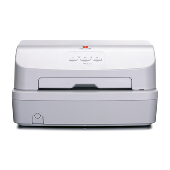
1. PRESENTATION OF THE MACHINE INTRODUCTION The PR2 plus is a medium-range specialized printer for the banking environment able to handle documents (both multi-copy and not) and passbooks for deposit/withdrawal transactions. This highly versatile printer can also be used for Public Administration front-office transactions or in Post Offices. -
Page 10: Technical Data
TECHNICAL DATA PRINT UNIT 1.2.1 The printing device consists of a needle matrix head with overheating protection sensor fitted on the transport carriage; contrast is provided by a spring-loaded deformation bar that permits adaptation of vertical position to document thickness at the printing position. Other features include faster speed of the printhead, increased to a maximum shooting frequency of 2295 Hz, and a new ribbon with a life of 10 million characters. - Page 11 Attributes Available fonts (depending on the active emulation) Alphanumeric native roman sans serif courier Optical reading OCR-A OCR-B single-row Barcodes Maximum packing of the barcode (module) depends on the dimensions of the needle of the printhead. Modules from 0.25 mm and multiple integers are possible. Types of barcodes supported EAN 8 Code 39...
- Page 12 XZAC4219-03...
- Page 13 Legend : currently present in the emulation indicated to be added xxxx number of the PNS that implements it, to be added in the basic version not present Direction of printing normal automatic on document feeder rotated by 270° rotation command Character attributes Normal double width...
-
Page 14: Print Ribbon
The body of the ribbon is personalized with the Olivetti logo. Black... -
Page 15: Console
CONSOLE 1.2.6 The PR2 Plus console comprises 3 keys, 5 leds and a display. The indications and commands are the same as those of the PR2 E. In emulations that permit this, it imitates the behavior of the display of the machine emulated; in other cases, it shows error messages, machine status, setup options. -
Page 16: Horizontal Magnetic Unit
It can be installed to the left or right of the paper path, as required by the customer. The passbook must be inserted against the respective side of feeder. Characteristics: R/W reference standards Binary coded decimal Olivetti Alignment method manual and autoborder Introduction side... -
Page 17: Throughput
Draft ECMA letter Draft EMULATIONS 1.2.12 The following emulations are possible: • Olivetti • IBM • Wincor SCANNER 1.2.13 A fast color scanner with a resolution of 600 dpi is included. The scanner features a fixed lower image acquisition element (CIS) and a mobile upper element that moves from the top down when activated. - Page 18 Scanner technical data type of scanner contact technology resolution 600 dpi illumination set of leds type of illumination red, green, blue (RGB) method of lighting monochrome or color (RGB) (factory alternative, monochrome and infrared) type of light control SW controlled light intensity SW controlled image acquisition...
-
Page 19: Certifications And Approvals
CERTIFICATIONS AND APPROVALS CERTIFICATIONS AND APPROVALS 230V POWER SUPPLY UNIT VERSION 1.3.1 Safety EN 60950 CE Marking: compliance with standards Electromagnetic Compatibility CE Marking: compliance with standards EN 55022 EN 55024 EN 61000-3-2 (harmonics) EN 61000-3-3 (flicker) Environmental Compatibility WEEE (2002/96/EC) Recycling: Directive ROHS (2002/95/EC) Hazardous substances: directive... -
Page 20: Documents That Can Be Handled By The Basic Machine
DOCUMENTS THAT CAN BE HANDLED BY THE BASIC MACHINE SINGLE FORM 1.4.1 65 x 245 mm Width 297 x 70 Length 0.07 ÷ 0.28 mm Single sheet thickness 60 ÷ 160 gr/m Single sheet weight 1+4 (medium weight) LQ: 1+6 Chemical paper copies 1+4 (medium weight) LQ: 1+6 Carbon paper copies... -
Page 21: Accessories
ACCESSORIES This paragraph describes the accessories available for the PR2 plus printer. RIBBON CARTRIDGE IN NYLON SNUG CART - BLACK 1.5.1 Ribbon cartridge for needle printhead, with life of 10 million characters. The cartridge is installed lifting the upper cover of the printer, with automatic positioning of the carriage, with machine ON or manual positioning with machine OFF, and lifting the print unit using the specific lever. -
Page 22: Location Of Main Components
LOCATION OF MAIN COMPONENTS COVER DISPLAY CONSOLE FRONT SLOT ON/OFF SWITCH Figure 1-2 REAR SLOT MAINS STANDARD SERIAL CONNECTOR INTERFACE CONNECTOR PARALLEL INTERFACE CONNECTOR USB INTERFACE CONNECTOR Figure 1-3 PRINTHEAD CARRIAGE LEVER FOR LIFTING THE UPPER PART OF THE MECHANISM Figure 1-4 1-14 XZAC4219-03... -
Page 23: Location Of Main Components Inside The Machine
LOCATION OF MAIN COMPONENTS INSIDE THE MACHINE CARRIAGE TRANSPORT MOTOR PRINTHEAD FLAT CABLE PRINTHEAD FRONT PAPER FEED SLOT SERVICES MOTOR Figure 1-5 MAGNETIC OPTIONS BOARD POWER SUPPLY MOTHERBOARD UNIT ON/OFF SWITCH Figure 1-6 XZAC4219-03 Service Manual 1-15... -
Page 24: General Block Diagram
GENERAL BLOCK DIAGRAM SWITCH / MAINS UNIT / MAINS CABLE POWER SUPPLY UNIT USB INTERFACE SERIAL INTERFACE PARALLEL INTERFACE ROLLER MOTOR TRANSPORT MOTOR PR2 PLUS MOTHERBOARD SERVICES MOTOR PRINTHEAD AUTOBORDER PHOTOSENSOR CARRIAGE RESET PHOTOSENSOR FRONT PAPER PRESENT PHOTOSENSOR CONSOLE 1-16 XZAC4219-03... -
Page 25: Firmware And Character Generators
The machine firmware comprises the following emulations: • Olivetti environment: STD 12/14 controlled protocol with native PR2 E environment and PR40+ and PR2845 emulation. Industry standard emulation IBM Proprinter II and Proprinter X24. •... - Page 26 The reference standards for the printable optical characters are as follows: Font Coding standard Dimensions/std form Print specifications OCR A EUROBANKING ISO 1073/1 ISO 1831 OCR B EUROBANKING ISO 1073/2 ISO 1831 Relationship between writing styles and emulation environment: Emulations Writing styles Selection HSD, DRAFT, NLQ1, NLQ2, LQ2,...
-
Page 27: Operating Controls
2. OPERATING CONTROLS The operating controls of the machine are as follows: • on/off switch • keys on the console • lever for lifting the upper part of the mechanism. KEYS ON THE CONSOLE ON/OFF SWITCH LEVER FOR LIFTING THE UPPER PART OF THE MECHANISM Figure 2-1 Operating controls... -
Page 28: On/Off Switch
2.1 ON/OFF SWITCH The on/off switch of the machine is of the two-position type. The switch is operated by a mechanism that runs cross the machine in a lengthwise direction. 2.2 CONSOLE The console of the machine comprises five leds and three keys. Figure 2-2 Console During machine set-up (par. -
Page 29: Meaning Of The Keys On The Console
MEANING OF THE KEYS ON THE CONSOLE 2.2.1 The keys perform the following functions: STATION 1: Books operator 1 (Olivetti STD 12/14) or assigns the printer to operator 1 (*) STATION 2: Books operator 2 (Olivetti STD 12/14) or assigns the printer... -
Page 30: Meaning Of The Leds On The Console
Machine in LOCAL mode (off-line) STATION 1: Indicator on: Waiting for document from operator 1 (Olivetti STD 12/14) or machine assigned to operator 1 or document present (*) Flashing indicator: Waiting for document from operator 1 or data present in the... -
Page 31: Lighting Of The Leds According To Fault Detected
2.2.3.1 LIGHTING OF THE LEDS ACCORDING TO FAULT DETECTED LEDS FAULT READY LOCAL POWER SUPPLY UNIT FAULT Fault on board: - Eprom - ROM - Microprocessor Fault on: - Fuses - Driver - Motors Fault on actuations board The motors do not perform any movement XZAC4219-03 Service Manual... -
Page 32: Meaning Of The Keys And Leds In Ibm 9068 Emulation (4722)
2.3 MEANING OF THE KEYS AND LEDS IN IBM 9068 EMULATION (4722) This paragraph describes the meaning of the keys and leds when the PR2 plus is in IBM 4722 emulation. MEANING OF THE KEYS 2.3.1 The keys perform the following functions: LOCAL/BREAK Switches the printer between On-line and Off-line status STATION 1/EJECT... -
Page 33: Meaning Of The Keys And Leds In Sni 4915 (4904) Emulation
2.4 MEANING OF THE KEYS AND LEDS IN SNI 4915 (4904) EMULATION This paragraph describes the meaning of the keys and leds when the PR2 plus is in SNI 4915 (4904) emulation. MEANING OF THE KEYS 2.4.1 The keys perform the following functions: LOCAL/BREAK Switches the printer between On-line and Off-line status STATION 1/EJECT... -
Page 34: Meaning Of The Keys
2.5 MEANING OF THE KEYS AND LEDS IN IBM PROPRINTER II/X24 - EPSON LQ 2550 EMULATION This paragraph describes the meaning of the keys and leds when the PR2 plus is in IBM Proprinter II/X24, EPSON LQ 2550 emulation. MEANING OF THE KEYS 2.5.1 The keys perform the following functions LOCAL/BREAK... -
Page 35: Lever For Lifting The Upper Part Of The Mechanism
2.6 LEVER FOR LIFTING THE UPPER PART OF THE MECHANISM The lever used to raise the upper part of the mechanism, positioned on the left-hand side of the machine, makes it possible to lift the mechanism and to access the paper path inside the machine, with the possibility of recovering a jammed document without having to switch off the printer. - Page 36 Figure 2-4 Lever for lifting the upper part of the mechanism Bringing the lever to its end of stroke position lifts the upper part of the mechanism, permitting access to the document feed zone Figure 2-5 Extraction of jammed document 2-10 XZAC4219-03...
-
Page 37: General Prescriptions For Installation
3. GENERAL PRESCRIPTIONS FOR INSTALLATION For optimal functioning of the printer and to avoid servicing for causes not ascribable to the product, comply with the prescriptions indicated below. POWER SUPPLY 3.1.1 Check that the outlet to which the printer is connected has a ground connection and is suitably scaled to provide the power required by the machine. -
Page 38: Unpacking And Installation Of The Machine
3.2 UNPACKING AND INSTALLATION OF THE MACHINE UNPACKING 3.2.1 Check the contents of the packing. This must contain: • PR2 plus printer • Mains cable • User manual • Ribbon cartridge • Sheet for cleaning the magnetic printhead for models with this option (not indicated in the figure below). Figure 3-1 Contents of the packaging XZAC4219-03... - Page 39 Unpacking and preparation of the printer for use: • Remove the machine from the bag. • Completely open the upper cover of the printer passing this over the stops so that it is positioned horizontally (illustration A in the following figure). •...
-
Page 40: Installation Of The Machine
INSTALLATION OF THE MACHINE 3.2.2 Position the machine where it is to be used, checking compliance with the indications provided in paragraph 3.1. Make sure that the voltage indicated on the dataplate matches that of the local power supply. Connect the mains cable and switch on the printer. -
Page 41: Contents Of The Print Test
• Visual checking of correct functioning of the 24 needles of the printhead (Needle test) • The configuration of the printer • The parameters set for IBM-PP and Olivetti emulations • To de-activate the test, switch off the printer. An example of the information returned by the test is provided on the next page. The contents of the test depend on the FW release installed on the printer. - Page 42 Figure 3-3 Example of print test XZAC4219-03...
-
Page 43: Connection To The System
3.4 CONNECTION TO THE SYSTEM In its basic configuration, the printer is equipped with an RS 232C serial port, a USB 2.0 port and a Centronics parallel port. A second RS 232C serial port (optional) is available if the printer is to operate in dual serial port mode. RS 232C SERIAL INTERFACE (STANDARD) 3.4.1 Connect the serial cable to the connector on the back of the machine. -
Page 44: Final Test
3.5 FINAL TEST After connecting the printer to the system, check the interface parameters. The PR2 plus is configured with a resident run-in test useful for checking the result of ordinary maintenance operations. To run the test, proceed as follows: Switch on the PR2 plus by pressing the STATION 2/EJECT with the cover open. -
Page 45: Operating Procedures
3.7 OPERATING PROCEDURES INSERTION OF THE DOCUMENT WITH AUTOMATIC ALIGNMENT 3.7.1 The resting surface of the casing facilitates introduction of documents in the machine. • With the printer on, place the document at the center of the front slot and insert it in the feed slot. •... -
Page 46: Insertion Of The Passbook
INSERTION OF THE PASSBOOK 3.7.2 Before inserting a passbook, fold this along the back until it remains completely opened in a horizontal position and check for any creased or torn pages in order to avoid poor quality printing and wrinkling of the pages during introduction. -
Page 47: Introduction Of Document For Horizontal Magn./ Micr Reading
INTRODUCTION OF DOCUMENT FOR HORIZONTAL MAGN./ MICR READING 3.7.3 A reference stripe for insertion of the check is provided on the front part of the cover. Figure 3-8 References for check insertion XZAC4219-03 Service Manual 3-11... -
Page 48: Ejection Of Documents
EJECTION OF DOCUMENTS 3.7.4 According to the application program, documents may be ejected as follows: • Returning these to where they were introduced manually (feed slot) • From the rear slot of the machine, starting from the front feed slot. The documents ejected from the front feed slot: •... - Page 49 • Push the ribbon guide down until it is released from the print cartridge. • Remove the old cartridge, pulling it outwards. Figure 3-10 Removal of the ribbon cartridge • Insert the cartridge in the feed gears, attaching this on the two sides and making sure that the pin (1) is inserted in the respective hole of the ribbon feed knob.
- Page 50 • Insert the ribbon guide from the front and then lift it so as to fasten it on the two flexible pins in the open slots of the cartridge on the back of the print roller (a click is heard). Figure 3-12 Attachment of the ribbon guide •...
-
Page 51: Replacement Of The Ribbon Cartridge With Machine On
3.7.5.2 REPLACEMENT OF THE RIBBON CARTRIDGE WITH MACHINE ON The ribbon cartridge may be replaced with the machine on, as explained below: • Open the cover of the printer; printing is blocked automatically. • Using the specific lever, lift the internal upper unit of the machine. •... -
Page 52: Paper Jam In The Front Feeder Area
3.7.6.1 PAPER JAM IN THE FRONT FEEDER AREA To remove a document that has jammed in the area of the front feeder, pull the document out carefully so as to avoid damaging it. Figure 3-14 Removal of a document in the area of the front feeder 3.7.6.2 PAPER JAM INSIDE THE PRINTER To remove a document that has jammed from inside the printer, proceed as follows:... -
Page 53: Paper Jam In The Area Of The Rear Slot
If scraps of paper remain jammed in inaccessible internal parts, these can be removed as follows: 1. Open the cover and switch on the printer with STATION 1/EJECT pressed. 2. Wait for the acoustic signal. 3. Pressing STATION 1/EJECT and/or STATION 2/EJECT, the paper will be moved forward and back so that it is possible to remove the scraps of paper that have jammed. -
Page 54: Self-Test, Set-Up And Calibration
4. SELF-TEST, SET-UP AND CALIBRATION 4.1 POWER-ON SELF-TEST The PR2 plus features a set of diagnostic tests that are activated automatically at power-on. Any FW or HW faults are highlighted by leds on the console. POWER-ON DIAGNOSTICS FOR PR2 E – PR2 PLUS TYPE OF FAULT LED RDY LED ST1... -
Page 55: Machine Set-Up
The Software tools are produced using suitable instruments and languages for insertion of the product in the environments where is connected. Drivers Are built on Olivetti native protocol. They comprise the enter range of capabilities that can be managed by Industry Standard applications. - reference command set... -
Page 56: Parameters Of The Configuration Mode Menu
- PARALLEL (compatible with DUAL) - RS 232 (2) (compatible with DUAL) - USB (if) RS232C (1) EMULATION: OLIVETTI – IBM Default emulation of the port. BAUD RATE: 9600 - 4800 - 2400 - 1200 Data transmission/reception speed. BIT/CHAR: 7 - 8 Data format at 7 or 8 bits. - Page 57 PAPER EDGE DETECTION: N - Y If enabled (Y), does not permit printing of lines wider than the sheet inserted. In the Olivetti environment, a jam (ESC r 1) is also generated. For reasons tied to the electronic HW, the width of the document is measured automatically only during the insertion phase.
- Page 58 IBM Menu EMULATION: P.P. II - X 24 Selection of IBM emulation (if) X24 AGM: N – Y Enables/disables the AGM function. PASSBOOK: N - Y Indicates whether the printer is enabled or not to handle passbooks. (if) Passbook Y BINDING: VERTICAL - HORIZONTAL Linked to the “PASSBOOK: Y”.
- Page 59 (if) ISO SET: OLI-UNIX ISO 8859/1 ISO 8859/2 ISO 8859/5 ISO 8859/6 ISO 8859/7 ISO 8859/8 ISO 8859/9 ISO 8859/15 PC TABLE: TABLE 1 - TABLE 2 Selection of the table of the character generator. CHAR DEFINITION: LQ - DRAFT Selection of print definition.
- Page 60 TOP MARGIN IBM-PP LIKE: N - Y Selects the type of top margin of the page (TOF) for the document managed. N - The value of the top margin will be between 4.23 mm (defined through calibration) for documents and 7.4 mm for passbooks.
- Page 61 Selecting “L (Left)” SW compatibility with the PR50 with left-hand alignment is obtained CHAR GENERATOR: IBM/PC - OLIVETTI selects the character generator. IBM emulation character set both PC and ISO (if) IBM CHAR SET: PC - ISO regardless of selection.
- Page 62 (if) PC CHAR SET: DK/N (GR) (INT) (LATIN 1) (GREEK) (LATIN 2) (CYRILLIC) (LATIN 5) (LATIN EURO) (THE) (CANADIAN FRENCH) (ARABIC) (NORDIC) (CYRILLIC) 1250 (PC WIN Latin2) 1252 (PC WIN Latin1) (if) ISO SET: OLI-UNIX ISO 8859/1 ISO 8859/2 ISO 8859/5 ISO 8859/6 ISO 8859/7 ISO 8859/8...
- Page 63 (if) OLIVETTI CHAR SET: DK/N S/SF STD 31 ARABIC USSR CIBC CHAR DEFINITION: DRAFT - LQ - OCRA - OCRB Selection of print definition. CPI: 5 - 10 - 12 - 15 - 16.6 - 17.1 Selection of printing pitch.
- Page 64 LINE LENGTH: 90 - 94 Selection of the maximum width of the print line, expressed in number of characters at 10 cpi. PRINTER REPLY SYNCRONIZED: N – Y Management of the DSR in transmission. STATUS REQUEST: NO WAIT – WAIT This parameter determines the timing of the status reply to an ESC j command.
- Page 65 (if) SIDE: R AFF: STD - USA Selects the width of the print line. LINE BUFFER PR2845 LIKE: N - Y Sets the width of the reception buffer to 2845 (512 Byte) or 8 K bytes. NATION: DK/N S/SF STD 31 CHAR DEFINITION: DRAFT - LQ Selection of print definition CPI: 10 - 12...
- Page 66 TOP OF FORM: 1 – 2 Selects the first or second printable line. STATUS REQUEST: NO WAIT – WAIT This parameter determines the timing of the status reply to an ESC j command. Selecting NO WAIT, the reply will be provided as soon as possible and in parallel with printing or paper movements.
-
Page 67: Settings
4.3 SETTINGS CALIBRATION OF THE PHOTOSENSORS 4.3.1 Machine photosensors are calibrated in the production phase. Changes in the electrical characteristics of the photosensors or the use of particular paper may require further calibration at the customer site. Machine photosensors that must be calibrated are: •... - Page 68 Back of the printer Head reset photrosensor (no calibration required) Impact head carriage Paper edge detection photosensor Optical fibers Optical fibers photos photos photos photos paper alignment photosensor Optical fibers Optical fibers Photosensor N° 1 Paper present Photosensor N° 2 Paper present Front of the printer Figure 4-1 Position of machine photosensors XZAC4219-03...
- Page 69 The block diagram for calibration of the photosensors is shown below. COVER OPEN KEYS ST1, LOCAL, ST2 PRESSED POWER-ON OF THE MACHINE ACOUSTIC SIGNAL AND LEDS ON MOVE THE HEAD TO THE LEFT AND CLOSE THE COVER ST 1 ST 2 READING OF VALUES FROM THE PHOTOSENSORS WITHOUT THE PAPER...
- Page 70 To carry out the photosensor calibration procedure, proceed as follows: Switch on the printer with the cover open holding down the three console buttons. Wait for the acoustic signal that indicates access to the calibration and adjustment procedure. Manually position the head towards the left-hand side and close the cover. Press the button of Station 1 twice to access the menu.
- Page 71 If calibration fails, the faulty photosensor will be indicated by the configurations of the leds. Pressing one the console button highlights any other faulty photosensors. If calibration is not completed correctly, it will not be possible to make the other calibrations or measurements. If calibration is successful, insert a sheet of A4 format paper in order to print the calibration values.
-
Page 72: Printing Of Photosensor Calibration Values
4.3.1.1 PRINTING OF PHOTOSENSOR CALIBRATION VALUES The calibration values of the photosensors are printed in order to obtain a reference between the previous calibration and that carried out subsequently. To calibrate the alignments, proceed as follows. Switch on the printer with the cover open and holding down the three buttons on the console. Wait for the acoustic signal that indicates access to the calibration and adjustment procedure, then close the cover. -
Page 73: Calibration Of Bidirectional Printing Alignment
CALIBRATION OF BIDIRECTIONAL PRINTING ALIGNMENT 4.3.2 The block diagram for calibration of print alignment is provided below. COVER OPEN KEYS ST1, LOCAL, ST2 PRESSED POWER-ON OF THE MACHINE ACOUSTIC SIGNAL AND LEDS ON. COVER CLOSED ST 1 ST 2 LEDS ST1 AND ST2 ON ST 1 ST 2 ALL LEDS ON... - Page 74 Calibration of alignments makes it possible to recover any misalignment during bidirectional printing caused by possible mechanical tolerances of the printer. After entering the calibration procedure, this will be carried out for the following print modes: • High Speed Draft 10 cpi •...
-
Page 75: Calibration Of The Top Of Form (Tof)
CALIBRATION OF THE TOP OF FORM (TOF) 4.3.3 The block diagram for calibration of the top edge of form (TOF) is given below. COVER OPEN KEYS ST1, LOCAL, ST2 PRESSED POWER-ON OF THE MACHINE ACOUSTIC SIGNAL AND LEDS ON ST 1 ST 2 LOCAL LED ST1 ED ST2 ON... - Page 76 This calibration makes it possible to set the distance between the top edge of the document and the first print line. This adjustment is activated only if, in the set-up of PR40+ emulation, “N” is selected for the "TOP MARGIN PR40 LIKE"...
-
Page 77: Calibration Of The Left Margin
CALIBRATION OF THE LEFT MARGIN 4.3.4 The block diagram for calibration of the left margin is provided below COVER OPEN KEYS ST1, LOCAL, ST2 PRESSED POWER-ON OF THE MACHINE SEGNALE ACUSTICO E LEDS ON ST 2 LED ST1 ON ST 1 LOCAL LED ON INSERT THE DOCUM. - Page 78 This calibration makes it possible to set the distance between the left-hand edge of the document and the first character printed. The value of the left-hand margin will always be used without the need for configurations from Set-up. To carry out this calibration, proceed as follows: Switch on the printer with the cover open holding down the three console buttons.
-
Page 79: Measurement Of Document Length
MEASUREMENT OF DOCUMENT LENGTH 4.3.5 The block diagram for measurement of the length of the form is provided below. COVER OPEN KEYS ST1, LOCAL, PRESSED POWER- ON OF THE MACHINE ACOUSTIC SIGNAL AND LEDS ON LOCAL LED ST1 ON LOCAL LOCAL LED ON INSERT THE DOCUM. - Page 80 It is necessary to measure the width of the form to permit faster management of the magnetic stripe of the passbooks. Selecting, via set-up, the "STRIPE HANDLING: FAST" item, the value read with the form measurement procedure will be used to determine the position of the magnetic stripe and for positioning of the stripe above the magnetic head (without having to make several measurements of passbook width).
-
Page 81: Checking Of Signal Skew
CHECKING OF SIGNAL SKEW 4.3.6 This check must be carried out with the machine completely assembled, presetting and specifying the magnetic device present on the machine in the Setup phase. The source of signals must be only the following sheet: AMPLITUDE AND SKEW SAMPLE code 713483R for horizontal magnetic device. -
Page 82: Maintenance Memory
4.4 MAINTENANCE MEMORY Accessing the serial number fields of the PR2 Plus and using the Toolbox (version 1.10_08 and higher) it is possible to read various data regarding its use from the printer. These data refer to the life of the printer (non-resettable data) and the life of any parts replaced following technical operations (resettable data). -
Page 83: Operations To Load The Firmware
4.5 OPERATIONS TO LOAD THE FIRMWARE On all models of the PR2 Plus, to update the firmware release, the Toolbox (version 1.10_08 and higher) must be installed. Note: Before installing the Toolbox, it is essential to remove any previous installation version from the Host. - Page 84 • Check that only the Firmware item has been selected in the File Format area. • Select the Open key. • Select the file containing the firmware to be transferred, confirming this with the Open key. XZAC4219-03 Service Manual 4-31...
- Page 85 • Select the Send key and wait until transfer of the firmware has been completed. • Calibrate the photosensors (par. 4.3.1). • Print the Self Test again, checking that the firmware release is that required. At this point, the printer is ready to operate. 4-32 XZAC4219-03...
-
Page 86: Machine Diagnostics Guide
5. MACHINE DIAGNOSTICS GUIDE 5.1 METHOD A technique for carrying out the operation is described below that may guide the less expert service engineer. ANALYSIS OF OCCURRENCE OF THE FAULT 5.1.1 The operator who has detected a malfunction is able to provide information about operating status and the error signals output by the printer when the fault occurred. -
Page 87: Identifying The Problem
IDENTIFYING THE PROBLEM 5.1.3 Examining all the information gathered (from the Operator, printer error signals, analysis of documents on which the fault has been encountered, repetition of the error when the machine is started, etc.), trace and isolate the problem that has occurred on the machine and which must be eliminated. In some cases, the fault may be caused by more than one problem: it is important therefore to separate the various problems and deal with these one by one. -
Page 88: Classification Of Faults
5.2 CLASSIFICATION OF FAULTS To facilitate tracing of faults, these have been divided into: • 5.3 faults at power-on • 5.4 faults during writing of the document • 5.5 faults during handling of the document • 5.6 faults during read/writing the magnetic stripe. The most frequent faults encountered and possible remedies are listed for each group. -
Page 89: Faults At Power-On
5.3 FAULTS AT POWER-ON FAULT POSSIBLE CAUSE Mains voltage absent/incorrect Mains cable damaged Mains cable only partially inserted Fuse blown Fault in the power supply unit Motherboard fault Fault in the front photosensors Fault in the carriage photosensor Fault in the rear photosensor Machine cover open Document jammed in machine Problems on interface connections... -
Page 90: Faults During Writing Of The Document
5.4 FAULTS DURING WRITING OF THE DOCUMENT FAULT POSSIBLE CAUSE Ribbon cartridge missing Ribbon to be replaced (out) Ribbon cartridge not inserted correctly Incorrect set-up parameters Irregular movement of the carriage Closing levers open Printhead fault Paper photosensor fault Printhead flat cable fault Transport motor fault Motherboard fault Adjustment of the document drive belt... -
Page 91: Document Movement Defects
5.5 DOCUMENT MOVEMENT DEFECTS FAULT POSSIBLE CAUSE Document not acc. to specs Document ruined Closing levers open Front photosensors fault Paper photosensor fault Rear photosensor fault Service motor fault Paper feed motor fault Motherboard fault Adjustment document feed belt Adjustment roller-needles Adjustment ribbon-needle protection tab Adjustment paper photosensor Adjustment print bar... -
Page 92: Faults During Read/Writing Of The Magnetic Stripe
5.6 FAULTS DURING READ/WRITING OF THE MAGNETIC STRIPE FAULT POSSIBLE CAUSE Incorrect set-up Passbook damaged Incorrect insertion of passbook in machine Magnetic printhead dirty Magnetic printhead fault Paper feed motor fault Magnetic unit board fault Motherboard fault Magnetic printhead movement motor fault XZAC4219-03 Service Manual... -
Page 93: Electrical Interconnections
6. ELECTRICAL INTERCONNECTIONS 6.1 GENERAL INTERCONNECTION DIAGRAM (MACHINES WITH SERIAL NUMBER 8.xxx.xxx) POWER SUPPLY MAINS CABLE TRANSFORMER BOARD RS232 SERIAL INTERFACE CENTRONIC OPTIONAL FAN PARALLEL POWER SUPPLY INTERFACE CARRIAGE OPTIONAL MOTOR REAR PHOTOSENSORS COVER OPEN SENSOR TRANSPORT MOTOR CONSOLE MAIN BOARD FRONT PHOTOSENSORS... -
Page 94: Motherboard (Machines With Serial Number 8.Xxx.xxx)
6.2 MOTHERBOARD (MACHINES WITH SERIAL NUMBER 8.xxx.xxx) An RS232 serial interface, a Centronics parallel interface and a USB interface are integrated in the board. Figure 6-1 PR2 plus motherboard XZAC4219-03... -
Page 95: General Interconnection Diagram (Machines With Serial Number 1.Xxx.xxx)
6.3 GENERAL INTERCONNECTION DIAGRAM (MACHINES WITH SERIAL NUMBER 1.xxx.xxx) POWER SUPPLY MAINS CABLE TRANSFORMER BOARD RS 232 SERIAL INTERFACE RS 232 SERIAL INTERFACE * EXPANSION SLOT CENTRONIC PARALLEL INTERFACE OPTIONAL REAR PHOTOSENSORS CARRIAGE MOTOR COVER SENSOR TRANSPORT MOTOR MAIN CONSOLE BOARD FRONT PHOTOSENSORS... -
Page 96: Motherboard (Machines With Serial Number 1.Xxx.xxx)
6.4 MOTHERBOARD (MACHINES WITH SERIAL NUMBER 1.xxx.xxx) A Centronics parallel interface and a USB interface are integrated on the board. VERSION WITH 1 RS232 SERIAL INTERFACE 6.4.1 F I 1 F I 2 LS11 RS16 DS10 DS12 DS14 DS17 RS17 DS18 DS11 DS15... -
Page 97: Version With No. 2 Rs232 Serial Interfaces
VERSION WITH NO. 2 RS232 SERIAL INTERFACES 6.4.2 F I 1 F I 2 LS11 RS13 DS6 DS7 TPCS1 RS16 RS18 DS10 DS12 DS17 DS14 RS17 DS18 DS15 DS11 DS16 TPCS2 DS13 DS19 DS21 DS23 DS26 RS19 DS20 DS24 DS25 DS27 DS22 RS20... -
Page 98: Magnetic Option Board
MAGNETIC OPTION BOARD The following board relating to the magnetic option present can be installed on the motherboard • PR2MAGN for management of the horizontal magnetic option The option installed is managed by the FW according to parameters defined in the machine set-up. VIEW OF THE BOARD AND POSITION OF THE CONNECTORS 6.5.1 Motherboard... -
Page 99: Console
6.6 CONSOLE Figure 6-4 Console Figure 6-5 Console board XZAC4219-03 Service Manual... -
Page 100: Alipr2 Plus
6.7 ALIPR2 PLUS Two codes may be assigned to the PR2 Plus power supply unit according to the mains voltage (115 V or 230 V) for which they are set. The value of fuse F1 also varies according to mains voltage. POWER SUPPLY UNIT 6.7.1 Figure 6-6 Power supply unit... -
Page 101: Preventive Maintenance
7. PREVENTIVE MAINTENANCE 7.1 CLEANING For correct functioning of the printer, it is advisable to clean parts of the machine periodically and after each servicing. CLEANING OF THE CASING 7.1.1 Switch off the printer, disconnect it from the power outlet and clean the casing with a damp cloth; do not use corrosive substances such as solvents, alcohol, benzene or products with abrasive components. -
Page 102: Maintenance
MANUAL PROCEDURE This type of cleaning is carried out by the service engineer outside the scheduled operations established by the automated procedure. A read magnetic stripe system command must be invoked also in this case. Insert the cleaning card facing in the right direction inside the feed slot; the machine will perform a read attempt and, at the end of this, will eject the card and indicate an error. -
Page 103: Lubrication
7.3 LUBRICATION Although relubrication is not required during the life of the machine, the service engineer should check this at each intervention, referring to the tables of parts to be lubricated. BASIC MACHINE LUBRICATION POINTS 7.3.1 DESCRIPTION CODE GREASE Print carriage sliding shafts Felt of the carriage 473150E Paper feed gears... -
Page 104: Horizontal Magnetic Unit/Micro Lubrication Points
DESCRIPTION CODE GREASE Print crossbar in the zones: 395115R Left-hand pin and ballast 473049G Guide hole central pin RH fork pin contact Inside of the holes for crosswise adjustment screws HORIZONTAL MAGNETIC UNIT/MICRO LUBRICATION POINTS 7.3.2 DESCRIPTION CODE GREASE Upper carriage sliding shaft (moderately, applying a drop to the sides of the shaft) Coupling between the pin and roller cage of the idler pulley Coupling between flap and pins on which this rotates... -
Page 105: Mechanical Adjustments
8. MECHANICAL ADJUSTMENTS To facilitate consultation, each adjustment is divided into: • Machine status. Describes the status of the printer required to make the adjustment. • Conditions to be checked. Indicates the points, values and tolerances to be complied with for correct functioning of kinematics. -
Page 106: Adjustment Of Document Drive Belt
8.1 ADJUSTMENT OF DOCUMENT DRIVE BELT MACHINE STATUS: Not significant. CONDITIONS TO BE CHECKED: Cogged belt (1) tensioned so as to obtain a deflection of 2.9 mm with a force of 200 g applied at the center of the span.. PROCEDURE: Loosen the lock nuts of the motor (2), establish conditions required and tighten the nuts (1). -
Page 107: Adjustment Of Printhead And Probes
8.2 ADJUSTMENT OF PRINTHEAD AND PROBES MACHINE STATUS: Photosensor in axis with head needles. CONDITIONS TO BE CHECKED: Distance between roller/ribbon protection bracket and needle profile. PROCEDURE: Position the probes, roller (1) and ribbon protection bracket (2) so as to obtain the positions indicated in the figure in relation to the needle profile and fasten these. -
Page 108: Adjustment Of The Print Bar (Machines With Serial Number 8.Xxx.xxx)
8.3 ADJUSTMENT OF THE PRINT BAR (MACHINES WITH SERIAL NUMBER 8.xxx.xxx) MACHINE STATUS: Printhead positioned co-axially with the axis of the screw used to make the adjustment. CONDITIONS TO BE CHECKED: Distance of 0.4 - 0.5 mm between print bar (2) and feeler roller (3). PROCEDURE: Bring the print unit to the writing position;... -
Page 109: Adjustment Of The Print Bar (Machines With Serial Number 1.Xxx.xxx)
8.4 ADJUSTMENT OF THE PRINT BAR (MACHINES WITH SERIAL NUMBER 1.xxx.xxx) MACHINE STATUS: Printhead positioned co-axially with the axis of the screw used to make the adjustment. CONDITIONS TO BE CHECKED: Distance of 0.4 - 0.5 mm between print bar (2) and feeler roller (3). PROCEDURE: Bring the print unit to the writing position;... -
Page 110: Adjustment Of Print Bar Parallelism And Leaf Spring Load On Basic Machine (Machines With Serial Number 8.Xxx.xxx)
8.5 ADJUSTMENT OF PRINT BAR PARALLELISM AND LEAF SPRING LOAD ON BASIC MACHINE (MACHINES WITH SERIAL NUMBER 8.xxx.xxx) MACHINE STATUS: Machine off without casing. CONDITIONS TO BE CHECKED: Check print bar parallelism and leaf spring load. PROCEDURE: The bar perpendicularity adjustment lever can be pre-regulated with tool code 9600303 according to drawing code 395130U. -
Page 111: Machine (Machines With Serial Number 1.Xxx.xxx)
8.6 ADJUSTMENT OF PRINT BAR PARALLELISM (MACHINES WITH SERIAL NUMBER 1.xxx.xxx) MACHINE STATUS: Machine off without casing. CONDITIONS TO BE CHECKED: Check print bar parallelism. PROCEDURE: The bar perpendicularity adjustment lever (1) can be pre-regulated with tool code 9600303 according to drawing code 395130U. -
Page 112: Check On Opening Of Front Band
CHECK ON OPENING OF FRONT BAND MACHINE STATUS: Rear structure closed and carriage completely to the right. CONDITIONS TO BE CHECKED: Distance between the front band and print bar. PROCEDURE: After checking correct adjustment of the band (as indicated in the paragraph above), close the rear structure and move the carriage to the right. -
Page 113: Adjustment Of Roller Gears
8.8 ADJUSTMENT OF ROLLER GEARS MACHINE STATUS: Upper part of the mechanism closed. CONDITIONS TO BE CHECKED: Maximum radial play between sprocket wheels (1) and (2) • 0.2 mm. PROCEDURE: Insert the specific tool code 2000500 between the hole of the gear (2) and the gear pin (1) and torque the two screws (3) to 6 + 0.5 Kgcm. -
Page 114: Adjustment Of Front Pressure Rollers
8.9 ADJUSTMENT OF FRONT PRESSURE ROLLERS MACHINE STATUS: Services cam with minimum lift zone facing towards the feeler roller. CONDITIONS TO BE CHECKED: Check play between the pressure roller (7) and the services cam (6). PROCEDURE: Insert a 0.5-mm thick probe (1) between the pressure (7) and drive (8) rollers. Operating on the shaft (2), position the three levers (3) in contact with the springs. -
Page 115: Adjustment Of Band Opening
8.10 ADJUSTMENT OF BAND OPENING MACHINE STATUS: With part of the upper mechanism in the work position and the print carriage in contact with the left-hand side, orient and secure the lever (1) on the band shaft leaving a clearance of 1.5 mm between crank and rocker arm (in relation to the profile of the carriage). -
Page 116: Adjustment Of Horizontal Magnetic/Micr Drive Belt Tension
8.11 ADJUSTMENT OF HORIZONTAL MAGNETIC/MICR DRIVE BELT TENSION MACHINE STATUS: Read/write carriage in reset position (end of stroke motor side). CONDITIONS TO BE CHECKED: Cogged belt (1) tensioned so as to obtain a deflection of 5 mm with a load of 60 g applied at the center of the stroke of the carriage. -
Page 117: Adjustment Of Horizontal Magnetic/Micr Closing Flap
8.12 ADJUSTMENT OF HORIZONTAL MAGNETIC/MICR CLOSING FLAP MACHINE STATUS: Read/write carriage in reset position (end of stroke motor side) and screw (1) which joins the semi tie-rods loosened. CONDITIONS TO BE CHECKED: Co-planarity between the closing flap and the front surface of the structure. PROCEDURE: Position the flap (2) in contact with the slot (3) operating in the compartment between the fork and toothing of the semi tie-rods (4);... -
Page 118: Positioning Of Horizontal Magnetic/Micr Pressure Roller
8.13 POSITIONING OF HORIZONTAL MAGNETIC/MICR PRESSURE ROLLER MACHINE STATUS: Pin of the bridge (4) on its minimum radius. With regard to the above, position the pressure roller (1) inside the conveyor (2) with a recess of 0.5-1 mm and, then phase the cam (3) so as to bring the pin of the bridge (4) on its minimum radius. With its screw (5) fasten the bridge on the shaft (check that the recess of the pressure roller is across the entire paper path). -
Page 119: Positioning Of Group On The Horizontal Magnetic/Micr Structure
8.14 POSITIONING OF GROUP ON THE HORIZONTAL MAGNETIC/MICR STRUCTURE MACHINE STATUS: Insignificant. CONDITIONS TO BE CHECKED: Co-planarity between the closing flap of the magnetic unit and the paper conveyor of the slot. PROCEDURE: Position the slots (1) in the half cut-outs (2) present on the sides of the machine. Draw up the lock-screws slightly (3). -
Page 120: Removal/Reassembly Of Parts
9. REMOVAL/REASSEMBLY OF PARTS Each removal operation is described as follows: Reference to any previous removal operations so as to reverse the disassembly procedure. Phases of the operation described in sequence. Notes: Indicate any references to adjustments to be made after reassembly, warnings or prescriptions to be complied with XZAC4219-03 Service Manual... -
Page 121: Prior Warnings
9.1 PRIOR WARNINGS • For maximum safety, before carrying out any part disassembly operation, switch off the printer and disconnect it from the mains. • Perform all the operations in a clean, free area. • Follow the procedure carefully; do not remove parts that must not be disassembled.. •... -
Page 122: Disassembly/Reassembly Operations Of The Basic Machine
9.2 DISASSEMBLY/REASSEMBLY OPERATIONS OF THE BASIC MACHINE DISASSEMBLY/REASSEMBLY OF THE CONSOLE 9.2.1 • Open the top cover of the machine. • Back off the two lock-screws (1) and remove the cover of the flat cable. • Disconnect the flat cable (2) from the console. •... -
Page 123: Disassembly/Reassembly Of The Cover
DISASSEMBLY/REASSEMBLY OF THE COVER 9.2.2 • Open the top cover of the machine. • Disconnect the flat cable of the console, as explained in the previous paragraph. • Release the pins of the cover (1) from the guides. • Using a tool (for example, a screwdriver) exert pressure on the hinges (2) and extract the cover. Figure 9-2 XZAC4219-03... -
Page 124: Disassembly/Reassembly Of The Casing
DISASSEMBLY/REASSEMBLY OF THE CASING 9.2.3 • Open the top cover of the machine (or, if necessary, remove it completely as explained above). • Release the pins (1) of the sound-absorbing material (2) and remove it. • Extract the front slot (3). •... - Page 125 • Lift the casing and place it to the side of the machine, as shown in the figure. • Back off the two screws (5) of the cover open switch and remove it. Figure 9-4 XZAC4219-03...
- Page 126 • Working from the lower side of the machine, back off the five lock-screws (6) of the baseplate. • Move the power supply switch (7) to the ON position. • Remove the baseplate as shown in the figure. Figure 9-5 XZAC4219-03 Service Manual...
-
Page 127: Disassembly/Reassembly Of The Mechanism
DISASSEMBLY/REASSEMBLY OF THE MECHANISM 9.2.4 • Disconnect the console and remove the casing as described above. • On both sides, back off the lock-screws (1) of the tabs that fasten the front rubber pads so that these can be removed from their housing. •... - Page 128 Figure 9-7 Machines with serial number 8.xxx.xxx Figure 9-8 Machines with serial number 1.XXX.XXX XZAC4219-03 Service Manual...
- Page 129 • Loosen the lock-screws (2) of the tabs that fasten the rear rubber pads so that these can be removed from their housing. • Back off the screw (3) that fastens the ground cables. • Lift the mechanism and separate it from the baseplate. Figure 9-9 9-10 XZAC4219-03...
-
Page 130: Disassembly/Reassembly Of The Flat Cables Of The Printhead
DISASSEMBLY/REASSEMBLY OF THE FLAT CABLES OF THE PRINTHEAD 9.2.5 • Remove the casing as explained above. • Free the cable clip (1) on the right-hand side of the structure, unclipping it from the inside (2) of the structure. • Remove the sound-proofing material (3). •... - Page 131 • Remove the printhead, unscrewing the two screws (7). • Slide out the two flat cables from the respective connectors (8) on the printhead. Figure 9-11 Warning: When reassembling the flat cable on the printhead, check that the path (9) indicated in the figure has been restored and that it does not interfere with the ribbon rewind gears which could cause irreparable damage to this during functioning of the machine.
-
Page 132: Disassembly/Reassembly Of The Printhead
DISASSEMBLY/REASSEMBLY OF THE PRINTHEAD 9.2.6 • Open the top cover and lift the upper part of the mechanism. • Remove the print cartridge. • Back off the two lock-screws (1) of the printhead. • Partially slide out the printhead from the carriage and disconnect the two flat cables (2) from the connectors on the printhead. -
Page 133: Disassembly/Reassembly Of The Printhead Photosensor
DISASSEMBLY/REASSEMBLY OF THE PRINTHEAD PHOTOSENSOR 9.2.7 • Remove the printhead as explained above. • Back off the lock-screw (1) of the printhead photosensor then extract the photosensor from its housing. • Disconnect the flat cable of the photosensor from the connector (2) on the printhead. •... -
Page 134: Disassembly/Reassembly Of The Upper Part Of The Mechanism
DISASSEMBLY/REASSEMBLY OF THE UPPER PART OF THE MECHANISM 9.2.8 • Remove the casing as explained above • From the front, lift the entire mechanism from the baseplate and rotate it partially so as to access the connectors of the motherboard. •... -
Page 135: Disassembly/Reassembly Of The Paper Feed Motor
DISASSEMBLY/REASSEMBLY OF THE PAPER FEED MOTOR 9.2.9 • Remove the mechanism as explained above. • Loosen the two lock nuts (1) of the motor and remove the document drive belt from the pulleys. • Loosen the nuts and extract the motor. Figure 9-15 Note: During reassembly, adjust the document drive belt (par. -
Page 136: Disassembly/Reassembly Of The Printhead Movement Motor
9.2.10 DISASSEMBLY/REASSEMBLY OF THE PRINTHEAD MOVEMENT MOTOR • Remove the upper part of the mechanism as explained above. • Loosen the lock-screw (1) of the idler pulley support slide and release the carriage movement belt from the motor pinion. • Unhook the flat cable of the printhead loosening the screw (2), then back off the three special lock-screws (3) and extract the printhead movement motor from its housing, taking care not to damage the ribbon feed gears. -
Page 137: Disassembly/Reassembly Of The Carriage Reset Photosensor
9.2.11 DISASSEMBLY/REASSEMBLY OF THE CARRIAGE RESET PHOTOSENSOR • Remove the casing as explained above. • From the front, lift the entire mechanism from the baseplate and rotate it partially so as to access the connectors on the motherboard. • Disconnect the cable of the carriage reset photosensor from the motherboard, releasing it from the related plastic clips. -
Page 138: Disassembly/Reassembly Roller Support Tray
9.2.12 DISASSEMBLY/REASSEMBLY ROLLER SUPPORT TRAY • Remove the casing as explained above. • Remove the mechanism, separating it from the baseplate as explained above. • Free the wire of the carriage reset photosensor from the plastic clips (1). Figure 9-18 Machines with serial number 8.xxx.xxx Figure 9-19 Machines with serial number 1.XXX.XXX XZAC4219-03 Service Manual... - Page 139 • Remove the upper part of the mechanism as explained above. • Back off the 4 screws (2) and remove the tray, taking care not to lose the transmission coupling (3) and the sound-proofing of the tray. Figure 9-20 Note: During reassembly, check correct positioning of the transmission coupling and of the sound-proofing before tightening the screws.
-
Page 140: Disassembly/Reassembly Of The Services Motor
9.2.13 DISASSEMBLY/REASSEMBLY OF THE SERVICES MOTOR • Remove the casing as explained above. • From the front, lift the entire mechanism from the baseplate and rotate it partially so as to access the connectors of the motherboard. • Disconnect the cable that connects the services motor to the motherboard. •... -
Page 141: Disassembly/Reassembly Of The Feeder Photosensors
9.2.14 DISASSEMBLY/REASSEMBLY OF THE FEEDER PHOTOSENSORS • Remove the mechanism as explained above. • Remove the upper part of the mechanism as explained above. • Remove the roller guard, removing the related M3 lock-screws (1). Figure 9-22 Machines with serial number 8.xxx.xxx Figure 9-23 Machines with serial number 1.XXX.XXX 9-22 XZAC4219-03... - Page 142 • Release the two springs (2) and slide out the document stop combs from their guides, after straightening the two tabs that prevent sliding out of the paper (3). Figure 9-24 Machines with serial number 8.xxx.xxx Figure 9-25 Machines with serial number 1.XXX.XXX XZAC4219-03 Service Manual 9-23...
- Page 143 • Release the bush (4) of the shaft and remove the bracket (5) of the alignment pressure rollers, then remove the entire group (6). Figure 9-26 • Back off the six lock-screws (7) of the conveyor (8). Figure 9-27 Machines with serial number 8.xxx.xxx 9-24 XZAC4219-03...
- Page 144 Figure 9-28 Machines with serial number 1.XXX.XXX • Back off the two lock-screws (9) of the photosensor support (10) and remove it. Figure 9-29 Machines with serial number 8.xxx.xxx XZAC4219-03 Service Manual 9-25...
- Page 145 Figure 9-30 Machines with serial number 1.XXX.XXX Note: When reassembling the conveyor, make sure that the coupling has been fitted before refitting the pressure roller assy. During reassembly, do not fasten the photosensor support until the conveyor has been fastened, as the conveyor has two reference pins for the photosensor support.
- Page 146 9.2.15 DISASSEMBLY/REASSEMBLY OF THE PLATEN (MACHINES WITH SERIAL NUMBER 8.xxx.xxx) • Remove the casing as explained above. • From the front, lift the entire mechanism from the baseplate and rotate it partially so as to access the connectors of the motherboard. •...
-
Page 147: Disassembly/Reassembly Of The Platen (Machines With Serial Number 8.Xxx.xxx)
9.2.16 DISASSEMBLY/REASSEMBLY OF THE PLATEN (MACHINES WITH SERIAL NUMBER 1.XXX.XXX) • Remove the casing as explained above. • From the front, lift the entire mechanism from the baseplate and rotate it partially so as to access the connectors of the motherboard. •... -
Page 148: Disassembly/Reassembly Of The Motherboard (Machines With Serial Number 8.Xxx.xxx)
9.2.17 DISASSEMBLY/REASSEMBLY OF THE MOTHERBOARD (MACHINES WITH SERIAL NUMBER 8.xxx.xxx) • Switch off the machine and disconnect the power cord. • Remove the casing as explained above. • Detach all the connections to the motherboard and disassemble the mechanism as explained above. •... - Page 149 • Back off the six lock-screws (3) of the motherboard. • Back off the two fasteners (4) of the standard serial interface connector. • Back off the two screws (5) of the Centronics interface connector. • Extract the motherboard from the baseplate of the printer. Figure 9-34 Note: During the reassembly of the metal sheet (4), fasten this from outside the supporting plate of the motherboard.
-
Page 150: Disassembly/Reassembly Of The Motherboard (Machines With Serial Number 1.Xxx.xxx)
9.2.18 DISASSEMBLY/REASSEMBLY OF THE MOTHERBOARD (MACHINES WITH SERIAL NUMBER 1.XXX.XXX) • Switch off the machine and disconnect the power cord. • Remove the casing as explained above. • Detach all the connections to the motherboard and disassemble the mechanism as explained above. •... - Page 151 • Back off the four lock-screws (3) of the motherboard. • Disconnect the cable (4) of the standard serial interface and, if present disconnect the cable of the optional serial interface. • Back off the two screws (5) of the Centronics interface connector. •...
-
Page 152: Disassembly/Reassembly Of The Fan Power Supply Unit
9.2.19 DISASSEMBLY/REASSEMBLY OF THE FAN POWER SUPPLY UNIT • Switch off the machine and disconnect the power cord. • Remove the casing as explained above. • Detach all the connections to the motherboard and disassemble the mechanism as explained above. •... -
Page 153: Disassembly/Reassembly Of The Power Supply Unit
9.2.20 DISASSEMBLY/REASSEMBLY OF THE POWER SUPPLY UNIT Note: If the fuse inside the power supply unit has blown, replace the entire unit as some of the components on the power supply unit board could be faulty. • Switch off the machine and disconnect the power cord. •... - Page 154 • Loosen the 2 lock-screws (2) of the switch. • Back off the four lock-screws (3) of the power supply unit, also removing the ground cables. • Extract the power supply unit. Figure 9-40 XZAC4219-03 Service Manual 9-35...
- Page 155 Figure 9-41 Note: During reassembly, pay particular attention to correct repositioning of the ground cables. If the unit is replaced, check that the power voltage is correct. 9-36 XZAC4219-03...
-
Page 156: Disassembly/Reassembly Of Basic Machine Options
9.3 DISASSEMBLY/REASSEMBLY OF BASIC MACHINE OPTIONS DISASSEMBLY/REASSEMBLY OF THE HORIZONTAL MAGNETIC/MICR 9.3.1 • Remove the casing as described above. • From the front, lift the entire mechanism from the baseplate and rotate it partially so as to access the connectors on the horizontal magnetic board (1). •... - Page 157 Figure 9-43 Machines with serial number 1.XXX.XXX Note: During reassembly, adjust positioning of the assy on the structure (par. 8.14). 9-38 XZAC4219-03...
-
Page 158: Disassembly/Reassembly Of The Horizontal Magnetic /Micr Motor
DISASSEMBLY/REASSEMBLY OF THE HORIZONTAL MAGNETIC /MICR MOTOR 9.3.2 • Remove the casing as explained above. • Remove the horizontal magnetic/MICR assy as explained above. • Disconnect the cable motor from magnetic options board. • Loosen the two nuts (1) and remove the motor with related protection shield. Figure 9-44 XZAC4219-03 Service Manual... -
Page 159: Disassembly/Reassembly Of The Horizontal Magnetic /Micr Printhead Assy
DISASSEMBLY/REASSEMBLY OF THE HORIZONTAL MAGNETIC /MICR PRINTHEAD ASSY 9.3.3 • Remove the casing as explained above. • Remove the horizontal magnetic/MICR assy as explained above. • Loosen the screw (1) and free the signals cable • Loosen the screws (2) and extract the MICR printhead (3). Figure 9-45 9-40 XZAC4219-03... - Page 160 UPDATING STATUS DATE UPDATED PAGES PAGES CODE 04/2007 1st EDITION XZAC4219 05/2007 2nd EDITION XZAC4219 10/2007 3th EDITION XZAC4219-03...