Table of Contents
Advertisement
Quick Links
Download this manual
See also:
Service Manual
Advertisement
Table of Contents

Related Manuals for Olivetti PR2 E


Summary of Contents for Olivetti PR2 E
- Page 1 Printer PR2 E SERVICE MANUAL Code Y100250-4...
- Page 2 PUBLICATION ISSUED BY: Olivetti TECNOST, S.p.A. Documentazione 77, Via Jervis - 10015 Ivrea (Italy) Copyright © 2001, Olivetti All rights reserved...
- Page 3 General (G) - DISTRIBUTION: April, 2001 - FIRST EDITION: NOTICE NOTICE NOTICE NOTICE NOTICE Olivetti TECNOST S.p.A. reserves the right to make changes to the product described in this manual at any time and without notice. Service Manual iii. Y100250-4...
- Page 4 OOOOO...
-
Page 5: Table Of Contents
TABLE OF CONTENTS 1. PRODUCT OVERVIEW INTRODUCTION ....................1 1.1.1 PR2 E FACTORY CONFIGURATION ............... 2 GENERAL MACHINE CHARACTERISTICS ............. 3 HORIZONTAL MAGNETIC DEVICE/MICR FEATURES ........4 PRODUCT VARIABLES ..................5 DOCUMENTS HANDLED BY THE BASIC MACHINE ........6 1.5.1 SINGLE AND MULTI-COPY FORMS ............... - Page 6 BUTTON AND LED FUNCTIONS IN THE SNI 4915 (4904) EMULATION ..7 2.4.1 BUTTON FUNCTIONS ..................7 2.4.2 LED INDICATIONS ................... 7 BUTTON AND LED FUNCTIONS IN THE IBM PROPRINTER II/X24 - EPSON LQ 2550 EMULATION ......8 2.5.1 BUTTON FUNCTIONS ..................8 2.5.2 LED INDICATIONS ...................
-
Page 7: Product Diagnosis
4. AUTODIAGNOSTICS, SET-UP AND ADJUSTMENTS ......1 POWER-ON DIAGNOSTICS ................1 PRINT TEST ....................... 2 PRINTER SET-UP ....................2 4.3.1 ACTIVATING THE SET-UP ................2 4.3.2 SUPPORT SOFTWARE ................... 2 4.3.3 CONFIGURATION PARAMETERS ..............3 SETTINGS ....................... 14 4.4.1 PHOTOSENSOR CALIBRATION ..............14 4.4.2 BI-DIRECTIONAL PRINT ALIGNMENT CALIBRATION ........ -
Page 8: Electrical Interconnections
6. ELECTRICAL INTERCONNECTIONS ............. 1 GENERAL PRINTER INTERCONNECTION DIAGRAM ........1 BAPR2 MAIN BOARD ..................2 6.2.1 MAIN BOARD VIEW AND LOCATION OF CONNECTORS........2 6.2.3 CONNECTOR PIN-OUT ..................3 MAGNETIC OPTIONS CARD ................5 6.3.1 CARD LOCATION AND IDENTIFICATION OF CONNECTORS ...... 5 6.3.2 VIEW OF THE PR2MAGN CARD .............. -
Page 9: Mechanical Adjustments
8. MECHANICAL ADJUSTMENTS .............. 1 DOCUMENT FEED BELT ADJUSTMENT............2 PRINT BAR ADJUSTMENT ................3 PARALLELISM ADJUSTMENT BETWEEN THE PRINT BAR AND LEAF ..SPRING LOAD IN THE BASIC MACHINE ............4 TAB ADJUSTMENT ..................5 FRONT TAB OPENING CHECK ................ 6 ROLLER GEAR ADJUSTMENT ................ - Page 10 9.2.11 ROLLER SUPPORT TRAY DISASSEMBLY/REASSEMBLY ......14 9.2.12 SERVICES MOTOR DISASSEMBLY/REASSEMBLY ........15 9.2.13 FEEDER PHOTOSENSORS DISASSEMBLY/REASSEMBLY ....... 16 9.2.14 PRINT BAR DISASSEMBLY/REASSEMBLY ..........19 9.2.15 MAIN BOARD DISASSEMBLY/REASSEMBLY ..........20 9.2.16 POWRER SUPPLY ASSY DISASSEMBLY/REASSEMBLY ......21 BASIC MACHINE OPTIONS DISASSEMBLY/REASSEMBLY ......22 9.3.1 HORIZONTAL MAGNETIC DEVICE/MICR DISASSEMBLY/REASSEMBLY .
-
Page 11: Product Overview
1. PRODUCT OVERVIEW 1.1 INTRODUCTION The PR2 E is a specialized mid-range banking printer. It can handle ordinary stationary (single and multicopy forms) and savings books for deposit/withdrawl transactions. Very versatile, this printer can also be used in Public Administration front-office environments and in Post offices. -
Page 12: Pr2 E Factory Configuration
1.1.1 PR2 E FACTORY CONFIGURATION The following table indicates the different PR2 E factory configurations: Commercial Name PR2 E S10 PR2 E D10 PR2 E D12 PR2 E D12 M PR2 E D10 DSP PR2 E S12 PR2 E S12 M... -
Page 13: General Machine Characteristics
CONSOLE Located on the printer cover, it has three buttons and five LEDs EMULATIONS PR40+, PR2 E and IBM PP II, X24, SNI 4915, IBM 9068 INTERFACE Standard RS 232C serial with the possibility of installing the following interface cards: - RS 232C serial + USB - Centronics parallel. -
Page 14: Horizontal Magnetic Device/Micr Features
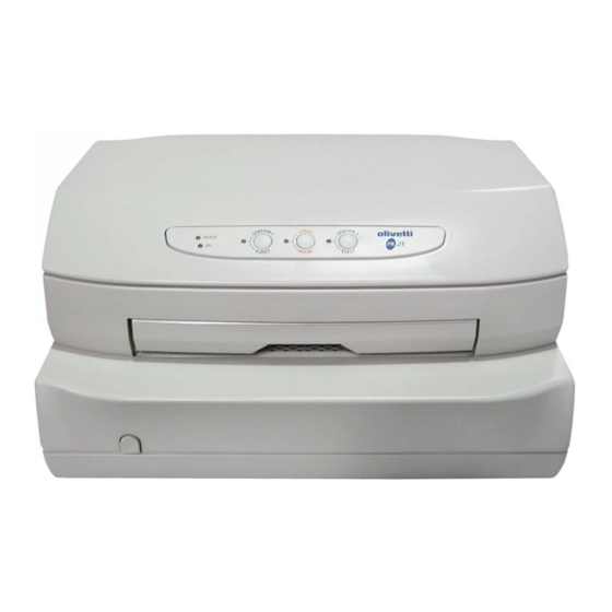
The following figure gives an overall view of the printer. Fig. 1-1 PR2 E Printer 1.3 HORIZONTAL MAGNETIC DEVICE/MICR FEATURES The Horizontal magnetic device/MICR (Magnetic Ink Character Recognition) device reads characters printed on checks with magnetic ink. Horizontal magnetic device/MICR applications are compatible with the CMC7 and E13B standards. -
Page 15: Product Variables
COR 005 Europe COR 041 Switzerland COR 042 Great Britain COR 043 Australia COR 050 USA COR 080 South Africa CRT FIRMWARE Olivetti standard + IBM X24 IBM 9068 + IBM X24 SNI 4915 + EPSON LQ 2550 Y100250-4 Service Manual... -
Page 16: Documents Handled By The Basic Machine
1.5 DOCUMENTS HANDLED BY THE BASIC MACHINE 1.5.1 SINGLE AND MULTI-COPY FORMS Maximum width 245 mm Minimum width 65 mm Maximum recommended length 297 mm Maximum accepted length 450 mm Minimum length 70 mm Single sheet weight 60 to 160 g/m Single sheet thickness 0.1 to 0.28 mm Transparency... -
Page 17: Savings Books
1.5.2 SAVINGS BOOKS Max. thickness with book open 1.8 mm Max. difference in level between pages 1.2 mm Cover thickness 0.2 to 0.5 mm Type of binding Thread-sewn, without metal staples or clips Book preparation Must be carefully flattened before being inserted into the machine Book with Vertical Seam Open book width 241.3 mm/9.5"... -
Page 18: Accessories
1.6 ACCESSORIES This section describes the accessories available for the PR2 E printer. BLACK NYLON SNUG CART RIBBON CARTRIDGE Ribbon cartridge specific for the needle printhead, with a life-span of more than 3.5 million characters. The cartridge is installed in the machine by opening the printer cover, with automatic printhead positioning if the printer is powered on or manual positioning if powered off, and lifting the print assembly by using the appropriate lever. -
Page 19: Locating The Printer's Major Components
1.7 LOCATING THE PRINTER'S MAJOR COMPONENTS COVER CONSOLE FRONT INSERTION SLOT POWER SWITCH REAR OUTPUT SLOT CONNETTORE CAVO RETE BREAKABLE SLOT COVER FOR THE INSTALLATION OF THE OPTIONAL STANDARD SERIAL INTERFACE INTERFACE CARD; SERIAL + USB OR CONNECTOR CENTRONICS PARALLEL OPEN COVER SENSOR PRINTHEAD AND CARRIAGE UPPER MECHANICAL ASSEMBLY... -
Page 20: Locating The Printer's Major Internal Components
1.8 LOCATING THE PRINTER'S MAJOR INTERNAL COMPONENTS PRINTHEAD FLAT CABLE PRINTHEAD SERVICES MOTOR CARRIAGE TRANSPORT MOTOR PAPER FEED MOTOR PINION FRONT PAPER FEED SLOT POWER SUPPLY UNIT OPTIONAL INTERFACE CARD MAGNETIC OPTIONS CARD INSTALLATION PINS POWER SWITCH MAIN BOARD CONSOLE Fig. -
Page 21: General Block Diagram
1.9 GENERAL BLOCK DIAGRAM 1.9.1 BASIC MACHINE POWER SWITCH/ POWER CORD POWER SUPPLY UNIT BASIC MACHINE INTERFACE SERIAL INTERFACE PARALLEL INTERFACE ROLLERS MOTOR CONSOLE PR2 E TRANSPORT MAIN BOARD MOTOR PRINTHEAD AUTOBORDER PHOTOSENSOR FRONT PAPER DETECTION PHOTOSENSOR CARRIAGE RESET PHOTOSENSOR SERVICES MOTOR... -
Page 22: Firmware And Character Generators
The machine firmware includes the following emulations: • Olivetti environment: STD 12/14 controlled protocol with the PR2 E native environment, PR40+ and PR2845 emulation. IBM Proprinter II and Proprinter X24 industry-standard emulation. -
Page 23: Character Sets
EMULATION CHARACTER SETS OLIVETTI CP SET, STD 15 Olivetti, ISO CP SET, ISO 1.10.3 PRINT MODES AND CHARACTER FONTS The following table indicates the characteristics of the different print modes:... - Page 24 PR50/PR40+ HSD, DRAFT, NLQ1, FROM SET-UP NLQ2, LQ2, OCRA, OCRB DRAFT, NLQ1, OCRA, OCRB FROM THE LINE PR2 E HSD, DRAFT, NLQ1, FROM SET-UP NLQ2, LQ2, OCRA, OCRB HSD, DRAFT, NLQ1, NLQ2, FROM THE LINE LQ2, OCRA, OCRB, ITALICO DRAFT...
-
Page 25: Operating Commands
2. OPERATING COMMANDS The machine's operating commands are the following: • power switch • console buttons • upper mechanical assembly lifting lever. CONSOLE BUTTONS UPPER MECHANICAL ASSEMBLY LIFTING LEVER POWER SWITCH Fig. 2-1 Operating Commands Y100250-4 Service Manual... -
Page 26: Power Switch
2.1 POWER SWITCH The printer is equipped with a two-pole power switch. The switch on/off command is provided by means of a rod that crosses the printer longitudinally. 2.2 CONSOLE The printer console has five LEDs and three buttons. Fig. 2-2 Console The console is also equipped with a circuit breaker (Dry-reed) that informs the board logics when the printer's top cover is opened. -
Page 27: Functions Of The Console Buttons
2.2.1 FUNCTIONS OF THE CONSOLE BUTTONS The buttons on the console perform the following functions: STATION 1: Reserves operator 1 (Olivetti STD 12/14) or assigns the printer to operator 1 (*) STATION 2: Reserves operator 2 (Olivetti STD 12/14) or assigns the printer to... -
Page 28: Meaning Of The Console Leds
2.2.2 MEANING OF THE CONSOLE LEDS When on, the LEDs inform of the following machine states: Machine powered on READY: Printer on-line/in receive mode or document present (*) LOCAL: Machine in LOCAL (off-line) When on: Waiting for a document from operator 1 (Oliveti STD 12/14) or machine STATION 1: assigned to operator 1 or document present (*) When flashing: Waiting for a document from operator 1 or data present in the... - Page 29 2.2.3.1 FAULT IDENTIFICATION CHART READY LOCAL FAULT Power supply unit failure On-board failure: - Eprom - ROM - Microprocessor Failure caused by: - Fuse - Driver - Motors Activation board The motors are not working failure Y100250-4 Service Manual...
-
Page 30: Button And Led Functions In The Ibm 9068 (4722) Emulation
2.3 BUTTON AND LED FUNCTIONS IN THE IBM 9068 (4722) EMULATION This section describes the button functions and LED indications of the PR2 E printer when in the IBM 4722 emulation. 2.3.1 BUTTON FUNCTIONS The buttons have the following functions: LOCAL/BREAK Toggles the printer between the on-line and off-line states. -
Page 31: Button And Led Functions In The Sni 4915 (4904) Emulation
2.4 BUTTON AND LED FUNCTIONS IN THE SNI 4915 (4904) EMULATION This section describes the button functions and LED indications of the PR2 E printer when in the SNI 4915 (4904) emulation. 2.4.1 BUTTON FUNCTIONS The buttons have the following functions:... -
Page 32: Button And Led Functions In The Ibm Proprinter Ii/X24 - Epson Lq 2550 Emulation
2.5 BUTTON AND LED FUNCTIONS IN THE IBM PROPRINTER II/X24 - EPSON LQ 2550 EMULATION This section describes the button functions and LED indications of the PR2 E printer when in the IBM Proprinter II/X24, EPSON LQ 2550 emulation. 2.5.1 BUTTON FUNCTIONS... -
Page 33: Upper Mechanical Assembly Lifting Lever
2.6 UPPER MECHANICAL ASSEMBLY LIFTING LEVER The upper mechanical assembly lifting lever (1) is located on the left-hand side of the printer and is used to lift the upper part of the mechanical assembly so that you can access the internal paper path so that paper jams can be cleared without needing to power off the printer. - Page 34 Fig. 2-4 Upper Mechanical Assembly Lifting Lever Pushing this lever as far as it goes lifts the upper part of the mechanical assembly thus granting you access to the paper path. Fig. 2-5 Removing a Jammed Sheet of Paper Y100250-4 2-10...
-
Page 35: Installation
3. INSTALLATION 3.1 GENERAL INSTALLATION PRECAUTIONS To ensure optimim printer functionality and to avoid making service calls for problems that are not directly caused by the product itself, bear in mind the information provided in the following sections. 3.1.1 ELECTRICAL POWER SUPPLY Make sure that the electrical wall outlet to which the printer is connected has a valid ground and that it is able to supply the power needed by the machine. -
Page 36: Unpacking And Installing The Machine
3.2 UNPACKING AND INSTALLING THE MACHINE 3.2.1 UNPACKING THE MACHINE Checking the box contents The following items should be contained in the packaging: - PR2 E printer - Power cord - Operator Manual - Ribbon cartridge - Magnetic head cleaning card (not shown in the figure below) for models equipped with this option. - Page 37 Unpacking and Setting-Up the Printer - Remove the machine from its protective bag. - Open the printer's top cover completely, forcing it to a horizontal position. - Push forward the two red plastic retainers that lock the print carriage (illustration 1 in the following figure).
-
Page 38: Installing The Machine
3.2.2 INSTALLING THE MACHINE Position the machine for operation, making sure that it complies with the information provided in section 3.1. Make sure that the voltage rating indicated on the electrical data plate corresponds to the local mains. Plug the power cord into the electrical wall outlet and then power on the printer. Make sure that the printer powers on by checking the mechanical reset and the lighting of the ON LED on the console. -
Page 39: Print Test Contents
- A graphical represetnation of 24-needle functionality (Needles test) - The configuration of the printer - The parameters defined for the IBM-PP and Olivetti emulations. To stop the print test, power off the printer. The following pages provide examples (Fig. 3-3 and Fig. 3-4) of the information provided by the tests. - Page 40 Fig. 3-3 Print Test Example - PR2 E Basic Version Y100250-4...
- Page 41 Fig. 3-4 Print Test Example - PR2 E + Horizontal Magnetic Device Y100250-4 Service Manual...
-
Page 42: Connection To The System
3.4 CONNECTION TO THE SYSTEM In its basic configuration, the printer is equipped with an on-board standard RS232 C interface and a slot for the installation in field of an optional interface card that connects to the specific connector on the main board. -
Page 43: Optional Serial Interface + Usb Interface Card
3.4.2 OPTIONAL SERIAL INTERFACE + USB INTERFACE CARD The optional serial interface + Universal Serial Bus (USB) interface card hosts both interfaces and is installed in the specific slot alongside the standard first serial interface on the rear of the printer. This interface card is shown in the following figure. - Page 44 Proceed as follows to install this optional card: - Power off the printer. - Using a screwdriver, break off the slot cover of the optional serial interface on the rear of the printer. - Insert the interface card in the slot and slide it along the guideways until it plugs into the related connector on the main board.
-
Page 45: Optional Ieee 1284 Parallel Interface Card
3.4.3 OPTIONAL IEEE 1284 PARALLEL INTERFACE CARD The optional parallel interface card hosts a 36-pin Centronics parallel interface. It is installed in the specific slot alongside the first serial interface on the rear of the printer. It is suggested to use an interface cable up to 1.5 meters long. - Page 46 Proceed as follows to install this optional card: - Power off the printer. - Using a screwdriver, break off the slot cover of the optional serial interface on the rear of the printer. - Insert the interface card in the slot and slide it along the guideways until it plugs into the related connector on the main board.
-
Page 47: Final Testing
3.5 FINAL TESTING After connecting the printer to the system, test its interface parameters. The PR2 E ha a resident run- in test which is useful to check the outcome of the ordinary maintenance intervention. Proceed as follows to perform this test: - Power on the PR2 E by pressing the STATION 2/EJECT button with the printer cover open. -
Page 48: Operating Procedures
3.7 OPERATING PROCEDURES 3.7.1 INSERTING A DOCUMENT WITH AUTOMATIC ALIGNMENT The front shelf on the case helps to insert the document in the printer. - With the printer powered on, place the document at the center of the front slot and then insert it into the feed slot. -
Page 49: Inserting A Savings Book
3.7.2 INSERTING A SAVINGS BOOK Before inserting a savings book, open it and press it along its spine so that it remains completely open horizontally. Make sure that pages of the book are not folded or ripped so as to prevent a poor print quality and errors during book insertion. -
Page 50: Inserting A Check For Horizontal Magnetic Device/Micr Read Operations
3.7.3 INSERTING A CHECK FOR HORIZONTAL MAGNETIC DEVICE/MICR READ OPERATIONS On the front of the machine cover there is a reference stripe to be used when inserting checks. Fig. 3-15 References for the Insertion of Checks Y100250-4 3-16... -
Page 51: Expulsion Of Processed Documents
3.7.4 EXPULSION OF PROCESSED DOCUMENTS The processed documents can be expelled from the printer, according to the application program, in the following ways: - Returning back to where the documents were manually inserted (paper feed slot) - From the printer's rear slot, starting from the front feed slot If the documents that are expelled from the front feed slot: - are less than 100 mm long, they will be released from the feed rollers - are 100 mm long or longer, they will remain gripped by the last set of rollers to avoid that the document... - Page 52 - Push the ribbon guide downwards until it releases from the print carriage. - Remove the old cartridge by pulling it outwards. Fig 3-17 Removing the Ribbon Cartridge - Insert the cartridge into the feed gears, hooking it on the two sides and making sure to insert pin (1) into the related hole of the ribbon feed knob.
- Page 53 - Insert the ribbon guide frontwards and then lift it until it hooks on to the two eleastic pins on the carriage's open slots behind behind the printhead platen (a "clack" sound is heard). Fig. 3-19 Hooking the Ribbon Guide - Turn the carriage knob counterclockwise (2) until the ribbon is taut and then remove tab (3).
-
Page 54: Paper Jams
3.7.5.2 REPLACING THE RIBBON CARTRIDGE WITH THE MACHINE POWERED OFF The ribbon cartridge can be changed with the machine powered on and by following the procedure listed below: - Open the printer cover; printing stops automatically. - Lift the upper mechanical assembly by using the appropriate lever. - Remove the used cartridge and replace it with a new one as previously described. - Page 55 3.7.6.1 PAPER JAMS AT THE FRONT DOCUMENT FEED SLOT To remove a jammed document from the front feed slot, carefully pull the document from the printer to avoid ripping it. Fig. 3-21 Removing the Document from the Front Feed Slot 3.7.6.2 PAPER JAMS INSIDE THE PRINTER Proceed as follows to remove a document from inside the printer: - Open the cover without powering off the machine.
- Page 56 If pieces of paper are jammed in unaccessible areas inside the machine, proceed as follows to remove them: 1) Open the cover and power on the printer while pressing the STATION 1/EJECT button. 2) Wait for an audible signal to sound. 3) Press STATION 1/EJECT and/or STATION 2/EJECT to move the paper forward/backward so that the jam can be cleared.
-
Page 57: Autodiagnostics, Setup And Adjustments
4. AUTODIAGNOSTICS, SETUP AND ADJUSTMENTS 4.1 POWER-ON DIAGNOSTICS At power on, besides a general reset the printer runs an autodiagnostic routine that checks the efficiency of all machine components. Upon the successful completion of the autodiagnostic routine the printer switches to the READY state (ON and READY LEDs lit). -
Page 58: Print Test
It highlights the features and performance offered by the printer in every configuration and optimizes the operational cycle so as to reach the maximum performance obtainable. - Drivers Based on the Olivetti native protocol, they integrate the entire range of features handled by industry-standard applications. - Reference command sets STD 12/14 PR2E - DLL driver provided WIN NT 4.x/2000, WIN 95/98... -
Page 59: Configuration Parameters
The optional interfaces are: - PARALLEL (DUAL-compatible) - RS 232 (2) (DUAL-compatible) - USB (when) RS232C (1) EMULATION: OLIVETTI – IBM Interface default emulation BAUD RATE: 9600 - 4800 - 2400 - 1200 Data transmissione/reception rate BIT/CHAR: 7 - 8 7- or 8-bit data format. - Page 60 PAPER EDGE DETECTION: N - Y When enabled (Y), inhibits the printing of lines that are wider than the sheet inserted. Causes a paper jam (ESC r 1) in the Olivetti environment. For electronic HW reasons, the width of the document is automatically measured only during the document insertion phase.
- Page 61 IBM Menu EMULATION: P.P. II - X 24 Selects the IBM emulation wanted (when) AGM: N – Y Enables/disables the AGM function. PASSBOOK: N - Y Indicates whether the printer is enabled or not to handle savings books. (when) Passbook Y BINDING: VERTICAL - HORIZONTAL Used when the “PASSBOOK: Y”...
- Page 62 (when) ISO SET: OLI-UNIX ISO 8859/1 ISO 8859/2 ISO 8859/5 ISO 8859/6 ISO 8859/7 ISO 8859/8 ISO 8859/9 ISO 8859/15 PC TABLE: TABLE 1 - TABLE 2 Selects the character generator table. CHAR DEFINITION: LQ - DRAFT Selects the character definition. CPI: 10 - 12 - 17.1 Selects the print pitch expressed in number of characters per inch.
- Page 63 TOP MARGIN IBM-PP LIKE: N - Y Selects the form's top margin (TOF). N - The Top Of Form value will be included between 4.23 mm (defined by the adjustment) for documents and 7.4 mm per savings books. Y - The Top Of Form value will be 4.23 mm for documents and 7.4 for passbooks.
- Page 64 PR50 with right-hand alignment. Selecting “L (Left)” ensures SW compatibility with the PR50 with left-hand alignment. CHAR GENERATOR: IBM/PC - OLIVETTI Selects the character generator. (when) IBM CHAR SET: PC - ISO IBM emulation PC or ISO character sets regardless of the selection made.
- Page 65 (when) PC CHAR SET: DK/N (GR) (INT) (LATIN 1) (GREEK) (LATIN 2) (CYRILLIC) (LATIN 5) (LATIN EURO) (IL) (CANADIAN FRENCH) (ARABIC) (NORDIC) (CYRILLIC) 1250 (PC WIN Latin2) 1252 (PC WIN Latin1) (when) ISO SET: OLI-UNIX ISO 8859/1 ISO 8859/2 ISO 8859/5 ISO 8859/6 ISO 8859/7 ISO 8859/8...
- Page 66 (when) OLIVETTI CHAR SET: DK/N S/SF STD 31 ARABIC USSR CIBC CHAR DEFINITION: DRAFT - LQ - OCRA - OCRB Selects the character definition. CPI: 5 - 10 - 12 - 15 - 16.6 - 17.1 Selects the print pitch.
- Page 67 LINE LENGTH: 90 - 94 Selects the maximum print line length expressed in numper of characters at 10 cpi. PRINTER REPLY SYNCRONIZED: N - Y DSR management during a transmission STATUS REQUEST: NO WAIT - WAIT Determines the timing of the status reply upon reception of an ESC j command.
- Page 68 (when) SIDE : R AFF : STD - USA Selects print line width. LINE BUFFER PR2845 LIKE: N - Y Defines the reception buffer length like the 2845 (512 Bytes) or to 8 Kbytes. NATION: DK/N S/SF STD 31 CHAR DEFINITION: DRAFT - LQ Selects the character definition.
- Page 69 TOP OF FORM: 1 - 2 Selects the first or second printable line. STATUS REQUEST: NO WAIT - WAIT Determines the timing of the status reply upon reception of an ESC j command. By selecting NO WAIT, the reply will be provided as soon as possible and simultaneously with the execution of a print job or paper movements.
-
Page 70: Settings
4.4 SETTINGS 4.4.1 PHOTOSENSOR CALIBRATION All machine photosensors are calibrated at the factory. However, a change in the electrical characteristics of the photosensors used or the use of non-standard paper may call for the photosensors to be recalibrated at the customer's site. All the photosensors present in the machine require calibration;... -
Page 71: Service Manual
Rear of the printer Printhead reset photosensor (does not require calibration) Paper edge detection photosensor Impact printhead carriage Fibre optics Fibre optics Photo 1 Photo 2 Photo 3 Photo 4 Front paper alignment photosensors Fibre optics Fibre optics Photo N° 1 Front paper detection Photo N°... - Page 72 Provided below is the photosensor calibration block diagram. COVER OPEN, ST1, LOCAL, ST2 PRESSED WHILE POWERING ON THE MACHINE ACOUSTIC SIGNAL AND LEDS ON MOVE THE PRINTHEAD TO THE LEFT AND CLOSE THE COVER ST 2 ST 1 READ PHOTOSENSOR BUTTON VALUES WITHOUT PAPER LED ST2 ON...
- Page 73 Proceed as follows to calibrate the photosensors: 1. Power on the printer with its cover open and while holding down the three buttons on the console. 2. Wait for the audible signal indicating that the printer has switched to the calibration and adjustment procedures.
- Page 74 Check for correct operation. Note: The parameters indicated above are useful indications to determine in which operating segment the PR2 E is positioned as far as document acceptance is concerned. 4-18 Y100250-4...
- Page 75 4.4.1.1 PRINTING PHOTOSENSOR CALIBRATION VALUES Printing photosensor calibration values iis useful as reference between one calibration and the next. Proceed as follows for alignment calibration: 1. Power on the printer with its cover open and while holding down the three buttons on the console. 2.
-
Page 76: Bi-Directional Print Alignment Calibration
4.4.2 BI-DIRECTIONAL PRINT ALIGNMENT CALIBRATION Provided below is the bi-directional print alignment calibration block diagram. COVER OPEN ST1, LOCAL, ST2 PRESSED WHILE POWERING ON THE PRINTER AUDIBLE SIGNAL AND LEDS ON ST 2 ST 1 LEDS ST1 AND BUTTON ST2 ON ST 1 ST 2 ALL LEDS ON... - Page 77 Alignment calibration corrects any bi-directional printing misalignment possibly caused by the printer's mechanical tolerances. Bi-directional printing alignment can be optimized by means of a calibration procedure which must be performed for each of the following print modes: - High Speed Draft 10 cpi - Draft 10 cpi...
-
Page 78: Top Of Form (Tof) Calibration
4.4.3 TOP OF FORM (TOF) CALIBRATION Provided below is the Top Of Form (TOF) calibration block diagram. COVER OPEN ST1, LOCAL, ST2 BUTTONS PRESSED WHILE POWERING ON THE PRINTER AUDIBLE SIGNAL, LEDS ON ST 1 ST 2 BUTTON LOCAL LEDS ST1 AND ST2 ON ST 1 ST 2 BUTTON... - Page 79 This calibration sets the distance between the form TOF and the first print line. The adjustment can only be activated if the "TOP MARGIN PR40 LIKE" parameter in the PR40+ emulation setup was set to "N". Proceed as follows to perform this calibration: 1.
-
Page 80: Left Print Margin Calibration
4.4.4 LEFT PRINT MARGIN CALIBRATION Provided below is the left print margin calibration block diagram. COVER OPEN ST1, LOCAL, ST2 BUTTONS PRESSED WHILE POWERING ON THE MACHINE AUDIBLE SIGNALS LEDS ON ST 2 ST1 LED ON ST 1 LOCAL LED ON LOAD THE DOCUMENT TO BE MEASURED THE DOCUMENT IS... - Page 81 This calibration sets the distance between the left edge of the and the first print character. The left margin value will always be used, without the need for set-up configurations. Proceed as follows to perform this calibration: 1. Power on the printer with its cover open and while holding down the three buttons on the console. 2.
-
Page 82: Document Length Measurement
4.4.5 DOCUMENT LENGTH MEASUREMENT Provided below is the document length measurement block diagram. COVER OPEN ST1, LOCAL, BUTTONS PRESSED WHILE POWERING ON THE MACHINE AUDIBLE SIGNAL LEDS ON LOCAL ST1 LED ON LOCAL LOCAL LED ON INSERT THE DOCUMENT TO BE MEASURED THE DOCUMENT IS MEASURED AND EXPELLED ST1 LED ON... - Page 83 Form length measurement is necessary for a rapid handling of a savings book magnetic stripe. By selecting the "STRIPE HANDLING: FAST" set-up option, the value provided by the form measurement procedure will be used to determine the position of the magnetic stripe and to position the stripe above the magnetic head without needing to further measure the length of the savings book.
-
Page 84: Skew And Signal Amplitude Control
4.4.6 SKEW AND SIGNAL AMPLITUDE CONTROL This check must be performed with the machine completely assembled and after having configured and specified, during set-up, the magnetic device installed on the printer. The signal source must be exclusively the following card: - AMPLITUDE AND SKEW SAMPLE code 713483R for horizontal magnetic unit. -
Page 85: Product Diagnosis
5. PRODUCT DIAGNOSIS 5.1 SERVICING MODES The following pages provide a technical approach to servicing that could be useful to less experienced field engineers. 5.1.1 FAULT DETECTION ANALYSIS The user who detected product malfunction can give information regarding the operating mode the printer was in when the malfunction occurred and the related error indications that were provided. -
Page 86: Identifying The Malfunction
5.1.3 IDENTIFYING THE MALFUNCTION Carefully examine all the information collected (from the Operator, printer error signals, analysis of the documents where the fault has occurred, repetition of the error when the machine is powered on, etc.) to recognize and identify the machine malfunction to be corrected. At times a malfunction is generated by more than one cause: it is important in such cases to isolate the faults and deal with them one at a time. -
Page 87: Fault Classification
5.2 FAULT CLASSIFICATION To make the search easier, the faults have been classified as follows: - 5.3 Power-on faults - 5.4 Document write faults - 5.5 Document handling faults - 5.6 Magnetic stripe read/write faults Each fault classification lists the more probable failures and their possible causes. The classification provided in this chapter cannot cover all the faults that could occur on the machine;... - Page 88 5.3 POWER ON FAULTS FAULT POSSIBLE CAUSE Incorrect/missing line voltage Damaged power cord Power cord partly inserted Blown fuse Faulty power supply unit Faulty main board Faulty front photosensors Faulty carriage photosensor Faulty rear photosensor Printer cover open Jammed paper Interface connection problems Interface line problems Incorrect set-up...
- Page 89 5.4 DOCUMENT WRITE FAULTS FAILURE POSSIBLE CAUSE Ribbon cartridge not installed Ribbon to be replaced (finished) Ribbon cartridge fitted incorrectly Incorrect set-up parameters Obstruction along the carriage stroke Closing levers open Faulty printhead Faulty paper photosensor Faulty head flat cable Transport motor Faulty main board Paper feed belt adjustment...
- Page 90 5.5 DOCUMENT HANDLING FAULTS FAILURE POSSIBLE CAUSE Document not within specifications Ruined document Closing levers open Faulty front photosensors Faulty paper photosensor Faulty rear photosensor Faulty services motor Faulty paper feed motor Faulty main board Document feed belt adjustment Needle-platen distance adjustment Ribbon-needle protection fin adjustment Paper photosensor adjustment Print bar adjustment...
-
Page 91: Magnetic Stripe Read/Write Failures
5.6 MAGNETIC STRIPE READ/WRITE FAILURES FAILURE POSSIBLE CAUSE Incorrect set-up Ruined savings book Incorrect savings book insertion Dirty magnetic head Faulty magnetic head Faulty paper feed motor Faulty magnetic device card Faulty main board Faulty magnetic head movement motor Y100250-4 Service Manual... - Page 92 OOOOO...
-
Page 93: Electrical Interconnections
6. ELECTRICAL INTERCONNECTIONS 6.1 GENERAL PRINTER INTERCONNECTION DIAGRAM ALIPR2E TO LINE VOLTAGE TRANSFORMER CARD RS 232 SERIAL INTERFACE CONSOLE TRANSPORT MOTOR PRINTHEAD AND PAPER BAPR2E PHOTOSENSOR MAIN OPTIONS INTERFACE BOARD OPTIONS INTERFACE MAGNETIC OPTIONS ROLLER MOTOR CARD CARRIAGE RESET PHOTOSENSOR PAPER FEED MOTOR FRONT... -
Page 94: Bapr2 Main Board
The BAPR2 main board has an onboard serial interface. The printer can be configured with one of the following two interface cards: - RS232 serial + UBS - Centronics parallel. 6.2.1 MAIN BOARD VIEW AND LOCATION OF CONNECTORS Fig. 6-1 Main Board on the PR2 E Y100250-4... -
Page 95: Connector Pin-Out
6.2.3 CONNECTOR PIN-OUT Provided below are the pinouts of the connectors on the PR2 E main board. Connector J33 is not indicates since it is only present on the BAPR2E Cost Improvement version. (RS 232 INTERFACE) (POWER SUPPLY) (CONSOLE) PIU35... - Page 96 (CARRIAGE RESET) (PAPER FEED MOTOR) (ROLLERS MOTOR) TRF1A MR01A TRF1B MR01B TRF2A MR02A FAZCA TRF2B MR02B (OPTIONS) (OPTIONS) (FRONT PHOTOSENSORS) ADSEL MAC21 FOCOM FDCDM MAC20 VCCAL2 MAC11 LECOM MAC10 LEAL3 MAPH2 LECOM MAPH1 FOCOM PIU35 VCCAL4 (OPTIONS) PIU35 FOAL3 TXDS SCKDS FOAN2 LEAN2...
-
Page 97: Magnetic Options Card
6.3 MAGNETIC OPTIONS CARD The following magnetic options card can be installed on the BAPR2 main board: - PR2MAGN, for the management of the horizontal magnetic device option The option installed is controlled by the FW according to the parameters defined during machine setup. 6.3.1 CARD LOCATION AND IDENTIFICATION OF CONNECTORS Fig. -
Page 98: View Of The Pr2Magn Card
6.3.2 VIEW OF THE PR2MAGN CARD Fig. 6-3 PR2MAGN Card Y100250-4... - Page 99 6.3.2.1 PR2MAGN CARD PIN-OUT (CONNECTION TO THE MAIN BOARD) (CONNECTION TO THE MAIN BOARD) MAC21 MAC20 DAWRM MAC11 DACOM MAC10 FAZMA MAPH2 VERMA MAPH1 PIU35 RESE0 PIU35 F2FDA PIU12 (MAGNETIC HEAD) (MAGNETIC DEVICE MOTOR) (MAGNETIC RESET PHOTO.) FAM0 WRI1 FAM1 WRI0 FAM2 LED1...
-
Page 100: Serial And Usb Interface Card
6.4 SERIAL AND USB INTERFACE CARD The installation of this interface card provides the printer with an additional serial RS232 and USB interface. 6.4.1 CARD VIEW AND LOCATION OF CONNECTORS Fig. 6-4 SERIAL and USB Interface Card Y100250-4... -
Page 101: Connector Pin-Out
6.4.2 CONNECTOR PIN-OUT Provided below is the pinout of the connectors on this interface card. (RS232 SERIAL INTERFACE) (USB INTERFACE) VBUS DCD1 DMENO REXD1 DPIU TXD1 DTR1 DSR1 CTS1 TAS01 TERRSE (INTERFACE) AD (15) AD (14) AD (13) AD (10) AD (11) AD (12) AD (9) -
Page 102: Parallel Interface Card
6.5 PARALLEL INTERFACE CARD The installation of this interface card provides the printer with a Centronics parallel interface. 6.5.1 CARD VIEW AND LOCATION OF CONNECTORS Fig. 6-5 Parallel Interface Card 6-10 Y100250-4... -
Page 103: Connector Pin-Out
6.5.2 CONNECTOR PIN-OUT Provided below is the pinout of the connectors on this interface card. (PARALLEL INTERFACE) (MAIN BOARD INTERFACE) AD (15) 19 GND AD (13) AD (14) STROBX 1 20 GND AD (11) AD (10) DACXX(0) 2 21 GND AD (9) AD (12) DACXX(1) -
Page 104: Console
6.6 CONSOLE YELLOW LED 2 YELLOW LED 3 YELLOW LED 5 YELLOW LED 4 GREEN LED 1 BUTTON 1 BUTTON 2 BUTTON 3 Fig. 6-6 Console YELLOW LED 5 YELLOW LED 4 YELLOW LED 3 YELLOW LED 2 GREEN LED 1 BUTTON 3 BUTTON 2 BUTTON 1... -
Page 105: Alipr2E Card
6.7 ALIPR2E CARD Two codes can be assigned to the ALIR2 card depending on the line voltage supported (115 V or 230 V). Also the value of fuse F1 varies according to the line voltage. 6.7.1 CARD VIEW AND LOCATION OF CONNECTORS Fig. - Page 106 OOOOO...
-
Page 107: Preventive Maintenance
PREVENTIVE MAINTENANCE CLEANING For a correct printer operation, it is suggested that the internal components of the machine be cleaned periodically and whenever the machine is serviced. 7.1.1 CLEANING THE CASE Power off the machine, unplug it from the electrical outlet and then clean its case using a damp cloth; avoid using corrosive substances such as solvents, alcohol solutions, petrol or abrasive components. -
Page 108: Maintenance
MANUAL PROCEDURE This cleaning procedure is performed by the field engineer and is not included in the programmed maintenance scheduled by the automatic procedure. Also in this case you need to run a system command for a magnetic stripe read operation. Insert the cleaning card in the front feed slot making sure to position it correctly: the machine will attempt to read the card after which it expels the card and signals an error condition. -
Page 109: Lubrication
7.3 LUBRICATION Although machine lubrication is not scheduled throughout its entire life span, during each service call you are expected to check the lubrication of the differnet parts by referring to the lubrication points table indicated below. 7.3.1 LUBRICATION POINTS ON THE BASIC MACHINE DESCRIPTION CODE GREASE... -
Page 110: Horizontal Magnetic Device/Micr Lubrication Points
DESCRIPTION CODE GREASE Print crosspiece in the following areas: 395115R Left pin and ballast 473049G Guide hole center pin Pin contact left bracket Inside the crosspiece adjustment screw holes 7.3.2 HORIZONTAL MAGNETIC DEVICE/MICR LUBRICATION POINTS DESCRIPTION CODE GREASE Upper carriage slide shaft (with moderation, placing a drop at the sides of the shaft) Return pulley, between pin and roller... -
Page 111: Mechanical Adjustments
8. MECHANICAL ADJUSTMENTS For easier consultation purposes, the mechanical adjustments have been divided into: - Machine condition. Describes the condition that the printer must be in in order to be able to perform a successful adjustment. - Objective adjustment. Indicates the points, values and tolerances to be observed to ensure good kinematic operation. -
Page 112: Document Feed Belt Adjustment
8.1 DOCUMENT FEED BELT ADJUSTMENT MACHINE CONDITION: Unimportant. OBJECTIVE ADJUSTMENT: The tension of timing belt (1) must sag 2.9 2 mm when applying 200 gr 2 gr at the center of the lower span. PROCEDURE: Loosen the motor securing nuts (2), tighten the belt accordingly and then tighten nuts (1) again. P=200 g 10 g Fig. -
Page 113: Print Bar Adjustment
8.2 PRINT BAR ADJUSTMENT MACHINE CONDITION: Testina di stampa posizionata coassiale con l'asse della vite su cui si compie la regolazione. OBJECTIVE ADJUSTMENT: A distance of 0.4/0.5 mm must be measured between the frame's lower shield (1) and the head of screw (2). -
Page 114: Parallelism Adjustment Between The Print Bar And Leaf Spring Load In The Basic Machine
8.3 PARALLELISM ADJUSTMENT BETWEEN THE PRINT BAR AND LEAF SPRING LOAD IN THE BASIC MACHINE MACHINE CONDITION: Machine powered off and with the case removed. OBJECTIVE ADJUSTMENT: Parallelism between the print bar and leaf spring load. PROCEDURE: The print bar perpendicularity adjustment lever must be previously adjusted using tool code 9600303 according to drawing code 395130U. -
Page 115: Tab Adjustment
8.4 TAB ADJUSTMENT MACHINE CONDITION: The upper mechanical assembly must be raised. OBJECTIVE ADJUSTMENT: Tab (1) must come into contact with print bar (2), and simultaneously the balancer (3) must come into contact with the tab support shaft (4). PROCEDURE: Loosen screw (5) and position the parts as explained. -
Page 116: Front Tab Opening Check
8.5 FRONT TAB OPENING CHECK MACHINE CONDITION: Rear frame assy closed and carriage moved completely to the right. OBJECTIVE ADJUSTMENT: Distance between the front tab and print bar. PROCEDURE: After making sure that the tab is adjusted correctly (as indicated in the previous section), close the rear frame assy and then move the carriage to the right. -
Page 117: Roller Gear Adjustment
8.6 ROLLER GEAR ADJUSTMENT MACHINE CONDITION: Upper mechanical assembly closed. OBJECTIVE ADJUSTMENT: Mesh between cogged wheels (1) and (2) with a maximum radial clearance of 0.2 mm between the teeth. Check this clearance throughout the entire wheel rotation. Adjust the two matings on the right-hand side of the printer. PROCEDURE: Turn screws (3) that secure the bushing, tightening them with a torque equivalent to 6 +0.5 Kgcm. -
Page 118: Front Pressure Roller Adjustment
8.7 FRONT PRESSURE ROLLER ADJUSTMENT MACHINE CONDITION: Service cam with its minimum throw area facing the probe roller. OBJECTIVE ADJUSTMENT: Make sure that there is a small clearance between the probe roller (7) and the service cam (6). (To check the correctness of the adjustment remove the probe and, without changing the fase, check for a slight clearance between the roller and cam without loading the springs. -
Page 119: Tab Opening Adjustment
8.8 TAB OPENING ADJUSTMENT MACHINE CONDITION: With the upper mechanical assembly in its working position and with the printhead carriage against the left side, position and secure lever (1) on the shaft with a clearance of 1.5 mm between the knob and balancer (with respect to the profile of the carriage). -
Page 120: Horizontal Magnetic Device/Micr Optioncarriage Feed Belt
8.9 HORIZONTAL MAGNETIC DEVICE/MICR OPTION CARRIAGE FEED BELT TENSION ADJUSTMENT MACHINE CONDITION: Read/write carriage in its reset position (end-of-stroke at the motor side). OBJECTIVE ADJUSTMENT: The tension of timing belt (1) so that a 5 mm sag is obtained when a force of 60 gr. is applied at the center of the carriage. -
Page 121: Horizontal Magnetic Device/Micr Door Adjustment
8.10 HORIZONTAL MAGNETIC DEVICE/MICR DOOR ADJUSTMENT MACHINE CONDITION: Read/write carriage at its reset position (end-of-stroke at motor side) and semi-tie rod joining screw (1) loose. OBJECTIVE ADJUSTMENT: Coplanarity between the door and the front surface of the frame. PROCEDURE: Fit the door (2) against the slot (3), working in the area between the leaf spring and the semi-tie rod tooth (4);... -
Page 122: Horizontal Magnetic Device/Micr Press Positioning
8.11 HORIZONTAL MAGNETIC DEVICE/MICR PRESS POSITIONING MACHINE CONDITION: Cam crank (4) against the shortest cam radius. Position press (1) inside conveyor (2) with an indent of 0.5-1 mm and then phase cam (3) so as to move cam crank (4) against its shortest radius. Secure the cam crank on the shaft with its screw (5). Make sure that the press is indented throughout the entire paper path). -
Page 123: Positioning The Assembly On The Horizontal Magnetic Device/Micr
8.12 POSITIONING THE ASSEMBLY ON THE HORIZONTAL MAGNETIC DEVICE/ MICR MACHINE CONDITION: Unimportant. OBJECTIVE ADJUSTMENT: Coplanarity between the magnetic device door and the slot paper conveyor. PROCEDURE: Hook slots (1) on the sides of the magnetic device frame onto pins (2) on the sides of the machine. Insert the securing screws (3). - Page 124 OOOOO...
-
Page 125: Disassembly/Reassembly Procedures
DISASSEMBLY/REASSEMBLY PROCEDURES For easier consultation, the disassembly procedures have been divided as follows: - 9.2.X disassembly of the basic machine, with no option installed - 9.3.X disassembly of the basic machine's horizontal magnetic device /MICR Each individual disassembly procedure is described in the following way: - Wherever possible, reference is made to previous disassembly procedures, so as to give a backward glance at the disassembly that comes prior to the one described. -
Page 126: General Disassembly/Reassembly Precautions
9.1 GENERAL DISASSEMBLY/REASSEMBLY PRECAUTIONS - To ensure maximum safety, before starting any disassembly operation power off the printer and unplug its power cord from the electrical outlet. - All operations should be performed in a clean and uncluttered area. - Follow the procedures carefully; do not unscrew parts that are not to be disassembled. - Store the disassembled parts in a clean place where there is no danger of them getting lost. -
Page 127: Disassembly/Reassembly Of The Basic Machine
9.2 DISASSEMBLY/REASSEMBLY OF THE BASIC MACHINE 9.2.1 CASE DISASSEMBLY/REASSEMBLY - Open the printer's top cover. - Remove the two securing screws (1) from the front of the case (2). Remove this front part of the case from the machine by pulling it in the direction of the arrows in the figure below. - Using a flat-blade screwdriver, release the case's two front snap features (3). -
Page 128: Console Disassembly/Reassembly
9.2.2 CONSOLE DISASSEMBLY/REASSEMBLY - Remove the printer case (section 9.2.1). - Loosen screws (1) and turn sideways the securing plates of the mechanical assembly rubber stops so as to release the front of the mechanical assembly from their slots. - Lift the front part of the mechanical assembly off the base of the printer, partly rotating it until you are able to reach console connector (2) on the main board. -
Page 129: Mechanical Assembly Disassembly/Reassembly
9.2.3 MECHANICAL ASSEMBLY DISASSEMBLY/REASSEMBLY - Remove the printer case (section 9.2.1) and console (section 9.2.2). - Lift the front part of the mechanical assembly off the base of the printer, partly rotating it until you are able to reach the connectors on the main board. - Unplug all the cables connecting the mechanical assembly to the main board, with the exception of the main board-to-power supply unit connection cable. -
Page 130: Printhead Flat Cable Disassembly/Reassembly
9.2.4 PRINTHEAD FLAT CABLE DISASSEMBLY/REASSEMBLY - Remove the printer case (section 9.2.1). - Free the cable clip (1) located on the right-hand side of the frame by unhooking it from the inside (2) of the frame itself. - Remove the soundproofing (3). - Loosen screw (4) that secures the rear cable fastener, rotate the fastener and then free the flat cables. - Page 131 - Remove the printhead by unscrewing the two screws (7). - Unplug the two flat cables from their connectors (8) on the printhead. Fig. 9-5 Warning: When reconnecting the flat cables to the printhead, make sure to restore the correct cable route (9) as indicated in the figure so that the cables do not interfere with the ribbon rewind gears;...
-
Page 132: Printhead Disassembly/Reassembly
9.2.5 PRINTHEAD DISASSEMBLY/REASSEMBLY - Open the printer cover and lift the mechanical assembly. - Remove the ribbon cartridge. - Unscrew the two screws (1) that secure the printhead. - Partly slide off the printhead from the carriage and unplug the two flat cables (2) from the connectors on the printhead. -
Page 133: Printhead Photosensor Disassembly/Reassembly
9.2.6 PRINTHEAD PHOTOSENSOR DISASSEMBLY/REASSEMBLY - Remove the printhead (section 9.2.5). - Remove screw (1) that secures the printhead photosensor and remove the photosensor from its seat. - Unplug the photosensor flat cable from its connector (2) on the printhead. - Replace the old photosensor with the new one, making sure that it rests against support shield (3);; replace and tighten the securing screw (1). -
Page 134: Disassembly/Reassembly
9.2.7 UPPER PART OF THE MECHANICAL ASSEMBLY DISASSEMBLY/REASSEMBLY - Remove the printer case (section 9.2.1) and console (section 9.2.2). - Lift the front part of the mechanical assembly off the base of the printer, partly rotating it until you are able to reach the connectors on the main board. -
Page 135: Paper Feed Motor Disassembly/Reassembly
9.2.8 PAPER FEED MOTOR DISASSEMBLY/REASSEMBLY - Remove the mechanical assembly (section 9.2.3) - Loosen the two nuts (1) that secure the motor and then release the document feed belt. - Remove the nuts and extract the motor. Fig. 9-9 Note: After reassembly, adjust the tension of the document feed belt (section 8.6). Y100250-4 Service Manual 9-11... -
Page 136: Printhead Movement Motor Disassembly/Reassembly
9.2.9 PRINTHEAD MOVEMENT MOTOR DISASSEMBLY/REASSEMBLY - Remove the upper part of the mechanical assembly (section 9.2.7). - Loosen the screw (1) that secures the return pulley support slide and then release the carriage movement belt from the motor pinion. - Release the printhead flat cable by loosening screw (2) and then unscrew the three special securing screws (3) and then remove the printhead movement motor being careful to avoid damaging the ribbon feed gears. -
Page 137: Carriage Reset Photosensor Disassembly/Reassembly
9.2.10 CARRIAGE RESET PHOTOSENSOR DISASSEMBLY/REASSEMBLY - Remove the printer case (section 9.2.1) and console (section 9.2.2). - Lift the front part of the mechanical assembly off the base of the printer, partly rotating it until you are able to reach the connectors on the main board. - Unplug the carriage reset photosensor cable from the main board and then release it from its plastic retaining clips. -
Page 138: Roller Support Tray Disassembly/Reassembly
9.2.11 ROLLER SUPPORT TRAY DISASSEMBLY/REASSEMBLY - Remove the printer case (section 9.2.1) and console (section 9.2.2). - Remove the mechanical assembly, separating it from the base of the machine (section 9.2.3). - Free the carriage reset photosensor wires from their plastic retaining clips (1). Fig. -
Page 139: Services Motor Disassembly/Reassembly
9.2.12 SERVICES MOTOR DISASSEMBLY/REASSEMBLY - Remove the printer case (section 9.2.1) - Lift the front part of the mechanical assembly off the base of the printer, partly rotating it until you are able to reach the connectors on the main board - Unplug the services motor connection cable from the main board. -
Page 140: Feeder Photosensors Disassembly/Reassembly
9.2.13 FEEDER PHOTOSENSORS DISASSEMBLY/REASSEMBLY - Remove the mechanical assembly (9.2.3). - Remove the upper part of the mechanical assembly (9.2.7). - Remove the roller shield after remov ing its M3 securing screws (1). Fig. 9-15 - Unhook the two springs (2), straighten the document stop bar slide-proof fins (3) and then slide the stop bar from its guideways. - Page 141 - Remove bushing (4) from alignment pressure roller shaft (5) and then remove the entire assembly (6). Fig. 9-17 - Remove the six screws (7) that secure the conveyor assembly (8). Fig. 9-18 Y100250-4 Service Manual 9-17...
- Page 142 - Remove the two screws (9) that secure photosensor support (10) and then remove the support. Fig. 9-19 Note: When refitting the conveyor assy, make sure that you refit the related bushing before refitting the pressure roller assy. During reassembly, do not secure the photosensor support until the conveyor assy is properly fitted since the conveyor assy has two reference pins for the photosensor support.
-
Page 143: Print Bar Disassembly/Reassembly
9.2.14 PRINT BAR DISASSEMBLY/REASSEMBLY - Remove the printer case (section 9.2.1) - Lift the front part of the mechanical assembly off the base of the printer, partly rotating it until you are able to reach the connectors on the main board. - Unplug all the cables with the exception of the printhead cables. -
Page 144: Main Board Disassembly/Reassembly
9.2.15 MAIN BOARD DISASSEMBLY/REASSEMBLY - Power off the machine and unplug the power cord from the electrical outlet. - Remove the mechanical assembly (section 9.2.3). - Unplug the power supply cable (1) that connects the main board to the power supply assy. - Remove the optional interface card (2), if installed. - Page 145 9.2.16 POWER SUPPLY ASSY DISASSEMBLY/REASSEMBLY Note: If the fuse inside the power supply has blown, replace the entire power supply assy since some components on the power supply board may be damaged. - Remove the mechanical assy (section 9.2.3) - Unplug the power supply cable (1) from the main board. - Unscrews the four screws (2) that secure the power supply and also remove the ground wires.
-
Page 146: Basic Machine Options Disassembly/Reassembly
9.3 BASIC MACHINE OPTIONS DISASSEMBLY/REASSEMBLY 9.3.1 HORIZONTAL MAGNETIC DEVICE/MICR DISASSEMBLY/REASSEMBLY - Remove the printer case (section 9.2.1). - Lift the front part of the mechanical assembly off the base of the printer, partly rotating it until you are able to reach the connectors on the main board (1). - Unplug the cables connected to the magnetic options card. -
Page 147: Horizontal Magnetic Device/Micr Motor Disassembly/Reassembly
9.3.2 HORIZONTAL MAGNETIC DEVICE/MICR MOTOR DISASSEMBLY/REASSEMBLY - Remove the printer case (section 9.2.1). - Remove the horizontal magnetic device/MICR assy (section 9.3.1). - Unplug the motor cable from the magnetic options card. - Loosen the two screws (1) and then remove the motor with its related protective shield. Fig. -
Page 148: Horizontal Magnetic Device/Micr Head Assy Disassembly/Reassembly
9.3.3 HORIZONTAL MAGNETIC DEVICE/MICR HEAD ASSY DISASSEMBLY/ REASSEMBLY - Remove the printer case (section 9.3.1). - Remove the horizontal magnetic device/MICR (section 9.3.1). - Loosen screw (1) to free the signals cable. - Loosen screws (2) and remove the MICR head (3). Fig. - Page 149 UPDATING STATUS DATE UPDATED PAGES PAGES CODE 04/2001 EDITION Y100250-4...