Table of Contents
Advertisement
Advertisement
Table of Contents

Related Manuals for Olivetti PR2


Summary of Contents for Olivetti PR2
- Page 1 Code Y683311W-01...
- Page 2 PUBLICATION ISSUED BY: Olivetti Lexikon, S.p.A. Documentation Copyright © 2000, by Olivetti Lexikon All rights reserved...
- Page 3 Q2 PR 2 SECTOR/RANGE PRODUCT: General (G) DISTRIBUTION: March 1997 FIRST EDITION: January 2000 SECOND EDITION: NOTICE Olivetti Lexikon, S.p.A. reserves the right to modify the equipment described in this manual at any time and without notice. Service Manual iii. 683311W...
-
Page 5: Table Of Contents
TABLE OF CONTENTS 1. OVERVIEW ........................ 1-1 INTRODUCTION ........................1-1 1.1.1 PR 2 FACTORY DEFAULT CONFIGURATION ............... 1-1 MACHINE OVERALL CHARACTERISTICS ................1-2 1.2.1 PRINTER CHARACTERISTICS ....................1-2 1.2.2 SCANNER CHARACTERISTICS ..................... 1-3 1.2.3 MICR CHARACTERISTICS ...................... 1-3 PRODUCT VARIABLES ......................1-5 DOCUMENTS THAT CAN BE PROCESSED BY THE BASIC MACHINE ....... - Page 6 3.4.2 IEEE 1284 PARALLEL INTERFACE ..................3-7 FINAL TESTING ........................3-8 INFORMATION FOR THE OPERATOR................... 3-8 OPERATING PROCEDURES ....................3-9 3.7.1 DOCUMENT INSERTION WITH AUTOMATIC ALIGNMENT ..........3-9 3.7.2 SAVINGS BOOK INSERTION WITH MANUAL ALIGNMENT ..........3-10 3.7.3 INSERTING A DOCUMENT FOR MICR READ OPERATIONS ..........3-11 3.7.4 INSERTING A DOCUMENT FOR SCANNER READ OPERATIONS ........
- Page 7 BOARD VIEW AND LOCATION OF CONNECTORS .............. 6-2 6.2.2 BOARD LAYOUT AND LOCATION OF CONNECTORS ............6-3 6.2.3 CONNECTOR SIGNALS ......................6-5 PR2 SCANNER CABLING DIAGRAM ..................6-7 PR2 SCANNER MAIN BOARD ....................6-8 6.4.1 BOARD VIEW AND LOCATION OF CONNECTORS .............. 6-8 6.4.2 BOARD LAYOUT AND LOCATION OF CONNECTORS ............
- Page 8 9. DISASSEMBLY/REASSEMBLY ................9-1 PRELIMINARY PRECAUTIONS ....................9-2 BASIC MACHINE DISASSEMBLY/REASSEMBLY PROCEDURES ........9-3 9.2.1 DISASSEMBLING/REASSEMBLING THE CASE ..............9-3 9.2.2 DISASSEMBLING/REASSEMBLING THE CONSOLE ............9-4 9.2.3 DISASSEMBLING/REASSEMBLING THE MECHANICAL ASSEMBLY ........9-5 9.2.4 DISASSEMBLING/REASSEMBLING THE PRINT HEAD FLAT CABLE........9-6 9.2.5 DISASSEMBLING/REASSEMBLING THE UPPER MECHANICAL ASSEMBLY .....
-
Page 9: Overview
1.1.1 PR2 FACTORY DEFAULT CONFIGURATION The different versions of the PR2 configured in factory are shows in the following table: Commercial name PR2 S10... -
Page 10: Machine Overall Characteristics
1.2 MACHINE OVERALL CHARACTERISTICS 1.2.1 PRINTER CHARACTERISTICS PRINT MODULE 24-needle impact print head Printing capabilities: 1original + 4 copies Savings book handling capabilities PRINT SPEED 76 cps @ 1/10" in LQ mode 115 cps @ 1/10" in NLQ mode 230 cps @ 1/10" in DRAFT mode 310 cps @ 1/10"... -
Page 11: Scanner Characteristics
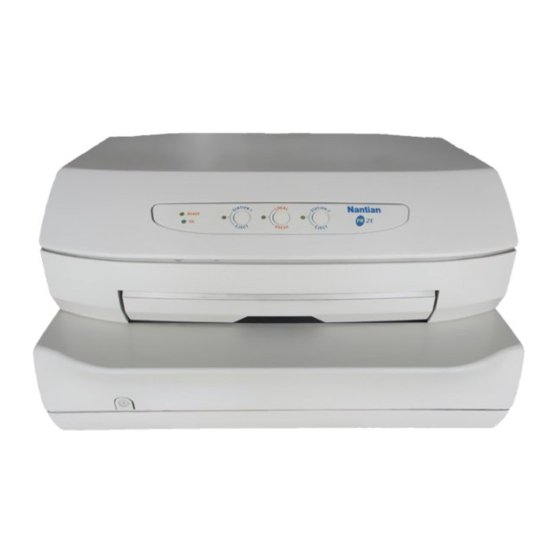
1.2.2 SCANNER CHARACTERISTICS SCANNER SENSOR TYPE Contact Image Sistem (CIS) READABLE WIDTH 210 mm NUMBER OF PIXELS 1728 RESOLUTION 8 dots/mm (203 dots/inch.) 16 shades of gray White/Black IMAGE FORMAT Bit stream SCANNING SPEED 4.05 msec/line DATA OUTPUT Analog 1.2.3 MICR CHARACTERISTICS The MICR (Magnetic Ink Character Recognition) device reads characters printed on checks with magnetic ink. - Page 12 Fig. 1-1 PR 2 Printer with Rounded Cover Fig. 1-2 PR 2 with Flat Cover 683311W...
-
Page 13: Product Variables
Spanish LIG 006 Italian DOCUMENT ALIGNMENT* DOC 007 Left-hand alignment DOC 009 Right-hand alignment COVER COV 000 Rounded cover COV 001 Flat cover * Document alignment must be specified for the PR2 S13 and PR2 D13 models. Service Manual 683311W... -
Page 14: Documents That Can Be Processed By The Basic Machine
1.4 DOCUMENTS THAT CAN BE PROCESSED BY THE BASIC MACHINE 1.4.1 SINGLE AND MULTICOPY MODULES Maximum width 245 mm Minimum width 65 mm Maximum recommended length 297 mm Maximum accepted length 450 mm Minimum length 70 mm Single sheet weight 60 to 160 g/m Single sheet thickness 0.1 to 0.28 mm... -
Page 15: Bank Books
1.4.2 BANK BOOKS Max. thickness with book open 1.8 mm Max. difference in levels between pages 1.2 mm Cover thickness 0.2 to 0.5 mm Type of binding Sewn with thread, without metal staples or clips Book preparation Must be carefully flattened before being inserted into the machine Book with vertical seam Open book width... -
Page 16: Supplies
1.5 SUPPLIES The machine supplies are: NYLON SNUG CART BLACK RIBBON CARTRIDGE This ribbon cartridge is specific for needle print heads and lasts more than 2.5 million characters. It can be installed into the printer after removing the front cover. INDELIBLE NYLON SNUG CART RIBBON CARTRIDGE Is the same as NYLON SNUG CART BLACK, but with indelible ink. -
Page 17: Location Of Major Controls
1.6 LOCATION OF MAJOR CONTROLS CASE CONSOLE FRONT SLOT POWER SWITCH REAR SLOT POWER CORD SOCKET SERIAL INTERFACE CONNECTOR PARALLEL INTERFACE CONNECTOR PRINT HEAD CARRIAGE COVER OPEN SENSOR UPPER MECHANICAL ASSEMBLY LIFTING LEVER Fig. 1-4 Locating the Major Controls Service Manual 683311W... -
Page 18: Location Of Major Components
1.7 LOCATION OF MAJOR COMPONENTS HEAD FLAT CABLE SERVICES MOTOR PRINT HEAD TRANSPORT MOTOR HORIZONTAL MAGNETIC BAND DEVICE MOTOR (PINION) ROLLERS MOVEMENT MOTOR ALI PR 2 BOARD TRANSFORMER MAGNETIC OPTIONS BOARD BA PR 2 BOARD Fig. 1-5 Locating the Major Components For noise reduction purposes, is used to toroidal transformer equipped with appropriate shield, as indicated in the following table: Horiz. -
Page 19: General Block Diagram
GENERAL BLOCK DIAGRAM 1.8.1 BASIC MACHINE WITH MAGNETIC OPTIONS POWER SWITCH/ POWER ASSEMBLY/ POWER CORD TRANSFORMER BASIC MACHINE SERIAL INTERFACE PARALLEL INTERFACE ROLLERS MOTOR CONSOLE TRANSPORT MOTOR MAIN BOARD PRINT HEAD AUTOBORDER PHOTOSENSOR FRONT PAPER PRES. PHOTO. REAR PAPER PRES. PHOTO. SERVICES MOTOR MAGNETICS BOARD... -
Page 20: Scanner Machine With Magnetic Options
1.8.2 SCANNER MACHINE WITH MAGNETIC OPTIONS POWER SWITCH/ POWER ASSEMBLY/ POWER CORD TRANSFORMER SCANNER MACHINE SERIAL INTERFACE PARALLEL INTERFACE ROLLERS MOTOR CONSOLE PR2 SCANNER TRANSPORT MOTOR MAIN BOARD PRINT HEAD AUTOBORDER PHOTOSENSOR FRONT PAPER PRES. PHOTO. REAR PAPER PRES. PHOTO. SERVICES MOTOR... -
Page 21: Firmware And Character Generators
1.9 FIRMWARE AND CHARACTER GENERATORS 1.9.1 MACHINE FIRMWARE The machine firmware includes the following emulations: - Olivetti PR 40+, PR 2845, NATIVE PR 2 and IBM PPII (4021/2) On PNS (Non Standard Products) is possible find the following optional emulations: - IBM 4722... -
Page 22: Character Sets
EMULATION CHARACTER SETS OLIVETTI CP SET, STD 15 Olivetti CP SET, ISO 1.9.3 PRINT MODES AND CHARACTER FONTS The following table lists the characteristics of the different print modes:... - Page 23 PR50/PR40+ VHSD, HSD, DRAFT, NLQ1, FROM SET-UP NLQ2, LQ2, OCRA, OCRB DRAFT, NLQ1, OCRA, OCRB FROM LINE PR2 Native VHSD, HSD, DRAFT, NLQ1, FROM SET-UP NLQ2, LQ2, OCRA, OCRB VHSD, HSD, DRAFT, NLQ1, NLQ2, FROM LINE LQ2, OCRA, OCRB, ITALIC DRAFT...
-
Page 25: Operating Commands
2. OPERATING COMMANDS Following are the printer’s operating commands: power switch, console and upper mechanical assembly lifting lever. CONSOLE UPPER MECHANICAL POWER SWITCH ASSEMBLY LIFTING LEVER Fig. 2-1 Operating Commands Service Manual 683311W... -
Page 26: Power Switch
2.1 POWER SWITCH The printer has a bipolar power switch located on the power supply board immediately below the power socket.The switch on/off command is sent through a rod that crosses the printer longitudinally. 2.2 CONSOLE The machine console has five LEDs and three keys. Ready Fig. -
Page 27: Meaning Of The Keys
Switches the machine status from Local (off-line) to Ready (on-line) and vice-versa. STATION 1/ With Olivetti interpreter, it assigns the machine to operator 1. EJECT With the IBM PP Ill emulation resident, it ejects any document that is in the machine. -
Page 28: Meaning Of The Leds
LOCAL Machine in Local mode (off-line) STATION 1 In the Olivetti emulation, it indicates that the printer has been assigned to Operator 1 STATION 2 In the Olivetti emulation, it indicates that the printer has been assigned to Operator 2. - Page 29 2.2.3.1 LED LIGHTING UP CHART, ACCORDING TO FAULT FOUND Others Power supply assy failure Board failure: - ROM - Microprocessor Failure on: - Fuses - Drivers - Motors The motors do not Activation board control any movement failure Service Manual 683311W...
-
Page 30: Ibm 4722 Emulation Console
2.3 IBM 4722 EMULATION CONSOLE The following figure shows the layout of the PR2 console in the IBM 4722 emulation. Ready Station 1 Break Station 2 Fig. 2-3 PR2 Scanner Console (IBM 4722 Version) 2.3.1 MEANING OF THE KEYS The keys have the following functions:... -
Page 31: Sni 4904 Emulation Console
When flashing indicates that data are to be printed but there is no paper inserted. When flashing together with the Ready LED, indicates an error condition. (paper jam). This PR2 version is equipped with a specific console which is different than the one installed on the standard product. Service Manual... -
Page 32: Upper Mechanical Assembly Lifting Lever
2.5 UPPER MECHANICAL ASSEMBLY LIFTING LEVER This lever is located on the left-hand side of the machine and is used to lift the upper part of the printer assembly to grant access to the internal paper path so that paper jams can be cleared without needing to power off the printer. - Page 33 Fig. 2-6 Upper Mechanical Assembly Lifting Lever Lifting this lever all the way rises the top part of the printer assembly thus granting access to the paper path way. Fig. 2-7 Removing Jammed Paper Service Manual 683311W...
-
Page 35: Installation
3. INSTALLATION 3.1 GENERAL INSTALLATION PRECAUTIONS To ensure that the printer operates at its best and to avoid servicing that does not arise from the product, the specifications indicated in the following sections must be observed. 3.1.1 ELECTRIC POWER SUPPLY Check the socket the printer is connected to ground and is able to supply the power required by the machine. -
Page 36: Unpacking And Installation
3.2 UNPACKING AND INSTALLATION 3.2.1 UNPACKING Checking the contents The following items should be contained in the packing: - PR 2 in the requested configuration - Main cable - User's manual - Ribbon cartridge for the needles head - Cleaning card for models with the horizontal/vertical /MICR magnetic option (not shown in the figure below). - Page 37 Printer start UP - Remove the machine from the protective bag - Completely open the printer’s top cover - Remove the two plastic brackets that block the print carriage and the top part of the printer in place during transportation Fig.
-
Page 38: Machine Installation
3.2.2 MACHINE INSTALLATION Position the machine where it will be operating, checking that the conditions set out in section 3.1 are respected. Make sure that the voltage indicated on the network plate is the same as the local power supply. Connect the main cable and power on the printer. -
Page 39: Print Test Contents
3.3.2 PRINT TEST CONTENTS The test gives the following Information: - The firmware release installed on the boards in the machine. - A visual verification of the functions of the print head’s 24 needles - The emulation currently used - The current printer parameters and options, when installed. On this page (Fig. -
Page 40: Test Analysis And Exiting The Test Environment
3.3.3 TEST ANALYSIS AND EXITING THE TEST ENVIRONMENT The test gives information concerning the functionalities of the options installed in the machine and on the machine set-up. A visual analysis of the print also permits an assessment of the printing quality. To exit from this environment, power off the machine. -
Page 41: Ieee 1284 Parallel Interface
3.4.2 IEEE 1284 PARALLEL INTERFACE The optional parallel Interface consists of a 36-pin Centronics connector. The use of an interface cable of up to 1.5 meters long is suggested. The ECP protocol is the data exchange protocol. S T R O B 0 1 1 9 L O G IC G R O U N D DA C X (0 ) 0 2 2 0 L O G IC G R O U N D... -
Page 42: Final Testing
- Print test. With the printer cover open, power on the PR2 while holding down the STATION 2 key. At the end of the reset routine the READY LED will remain on, in which case close the cover and insert a sheet of A4 paper (self-test printing). -
Page 43: Operating Procedures
3.7 OPERATING PROCEDURES 3.7.1 DOCUMENT INSERTION WITH AUTOMATIC ALIGNMENT The front shelf on the case helps the inspection of the document into the machine. - With the printer powered, place the document at the center of the front slot and insert it into the feed slot. -
Page 44: Savings Book Insertion With Manual Alignment
3.7.2 SAVINGS BOOK INSERTION WITH MANUAL ALIGNMENT - The savings book must be aligned manually if the printer is equipped with the vertical magnetic band device option and if the book has a magnetic strip on its cover. - During insertion, the savings book with magnetic strip must be placed against the side of the insertion slot (right or left depending on the magnetic installed in the printer). -
Page 45: Inserting A Document For Micr Read Operations
3.7.3 INSERTING A DOCUMENT FOR MICR READ OPERATIONS On the front of the machine cover there is a reference strip to be used when inserting cheques. Fig. 3-9 References for Inserting Cheques 3.7.4 INSERTING A DOCUMENT FOR SCANNER READ OPERATIONS On the front of the machine cover there is a serigraphed strip indicating the scanner's reading area. -
Page 46: Expulsion Of Processed Documents
3.7.5 EXPULSION OF PROCESSED DOCUMENTS The processed documents can be elected from the machine, according to the user program, in the following way: - Returning back to where they were manually introduced (line feed device). - From the machine rear slot, starting from the front feeder. The documents are expelled from the front feed slot as follows: - When shorter than 100 mm, they will be released by the feed rollers - When 100 mm or longer, they will remain gripped by the last set of rollers to avoid that the document... - Page 47 - Push the ribbon guide downwards until it releases from the print carriage. - Remove the old cartridge by pulling it outwards. Fig 3-12 Removing the Ribbon Cartridge - Insert the cartridge into the feed gear by hooking it on the two sides. Fig.
- Page 48 - Insert the ribbon guide frontwards and then move it upwards until it hooks on to the two elastic pins to the carriage’s open slots behind the print head platen (a “clack” is heard). Fig. 3-14 Hooking the Ribbon Guide - Turn the cartridge knob counter clockwise (1) until the ribbon is tight and then remove the tab (2).
-
Page 49: Paper Jams
3.7.6.2 REPLACING THE RIBBON CARTRIDGE WITH THE MACHINE POWERED ON The ribbon cartridge can be changed with the machine powered on and by following the procedure listed below: - Open the printer cover. Printing stops automatically. - Lift the upper assembly by using the appropriate lever. - Remove the used cartridge and replace it with a new one, as previously described. - Page 50 3.7.7.1 PAPER JAMS AT THE FRONT DOCUMENT INSERTION SLOT To remove a jammed document from area A (front feeder), carefully pull the document from the printer to avoid ripping it. Fig 3-16 Removing the Document from the Front Insertion Slot 3.7.7.2 PAPER JAMS INSIDE THE PRINTER Proceed as follows to remove a document from area B (inside the printer): - Open the cover without powering off the printer...
- Page 51 If some pieces of paper remain jammed in inaccessible areas inside the printer, proceed as follows to remove them: 1) Open the cover and power on the printer with the ST1 key pressed, 2) Wait for the audible signal to sound. 3) By pressing ST1 and/or ST2 (key 3, without any indication, for machines running the SNI ND 90 emulation) the paper will be moved forward/ backward so that the jammed pieces of paper can be cleared.
-
Page 53: Autodiagnostics, Setup And Settings
4. AUTODIAGNOSTICS, SETUP AND SETTINGS 4.1 POWER-ON DIAGNOSTICS At every power-on, besides the general reset, the printer runs an autodiagnostics cycle to check the efficiency of its parts. After the autodiagnostics, if no faults have been revealed, the printer remains in READY condition (ON and READY LEDs lit on the console). -
Page 54: Print Test
4.2 PRINT TEST With the print test the operator can obtain a printout of the machine set-up. The instructions to run the test are given in section (off line tests). 4.3 STANDARD MACHINE SET-UP The set-up environment is only to be accessed by the service engineer since many of the selectionable parameters serve to personalize the machine or installed option and must not be changed. -
Page 55: Configuration Parameters
This section lists the parameters to be found in the set-up, with the alternative settings and their meanings. The default values are indicated in bold print. 4.3.2.1 CONFIGURATION MODE MENU PARAMETERS Choice of code interpreter to be used. EMULATION IBM - OLIVETTI Saves the emulation change made on line in EEPROM. EMULATION TEMPORARY SELECTION PERMANENT... - Page 56 In this mode, the first interface that receives the signal becomes active thus automatically blocking the other. Reception on the serial line activates the Olivetti PR 40+ emulation, while reception on the parallel line activates the IBM PPII emulation.
-
Page 57: Service Manual
STATION 2=SKIP PRESS LOCAL TO CONTINUE ST 1 ST 2 LOCAL Printing CONFIGURATION MODE Printing: Configuration Mode EMULATION: OLIVETTI EMULATION SELECTION: TEMPORARY DRAFT SPEED: NORMAL Printing: IBM Menu LOCAL ST 1 LQ TYPE: NLQ1 PASSBOOK: Y PAPER WIDTH: FIRST LINE... - Page 58 Emulaz. PR 40+ PASSBOOK: Y LOCAL ST 1 BINDING: VERTICAL SIDE: L LINE BUFFER PR40 LIKE: N ST 2 Printing EMULATION: PR 2845 OLIVETTI CHAR GENERATOR LOCAL ST 1 OLIVETTI Printing: PC CHAR SET: CHAR SET: Emulaz. PR 2845 437 (INT)
- Page 59 Printing: Emulaz. PR2 PASSBOOK: Y BINDING: HORIZONTAL CHAR GENERATOR: OLIVETTI OLIVETTI CHAR SET: INT SELECTION: (if) IBM CHAR SET: PC PC CHAR SET: 437 (INT) (if) IBM CHAR SET: ISO SET PNS # 3416: N ISO SET: OLI-UNIX PNS # 3517: N...
- Page 60 4.3.2.2 IBM MENU PARAMETERS PASSBOOK Y - N Indicates whether the printer is enabled (Y) or not (N) by default to process passbooks. BINDING HORIZ. - VERT. Indicates whether the passbook fed into the printer is bound horizontally or vertically. SIDE: L - R Selecting R (Right) provides SW compatibility with the PR50 with right alignment.
- Page 61 CR+ LF Y - N Selects (Y) or (N) for automatic line feed (LF) at every carriage return command received (CR). ZERO SLASH N - Y Enables/disables the printing of slashed zero. LINE LENGTH 80 - 90 Selects the maximum length of the printed line as a number of characters (10 cpi).
- Page 62 4.3.2.3 OLIVETTI PR 2 MENU PARAMETERS IF EMULATION = PR2 PASSBOOK Y - N Indicates whether printer is enabled (Y) or not (N) by default to process passbooks. BINDING: HORIZ. - VERT. Character generation selection. CHAR OLIVETTI - GENERATOR IBM/PC...
- Page 63 RESET WITH Y - N Sets (Y) or not (N) the automatic ejection of the EJECT document in the machine every time the printer makes a general reset. PRINTER Y - N DSR (Data Send Ready) management in transmission. REPLY SYNCRONIZED: STATUS REQUEST: NO WAIT - Determines the timing of the status reply upon reception WAIT...
- Page 64 4.3.2.4 OLIVETTI PR 40+ MENU PARAMETERS IF EMULATION = PR40+ Indicates whether the printer is enabled (Y) or not (N) PASSBOOK Y - N to handle passbooks by default. Indicates whether the passbook fed into the printer is BINDING: HORIZ - VERT bound horizontally or vertically.
- Page 65 (Only for CHAR SET = IBM/PC) PC CHAR SET: DK/N 210 (GR) 220 (E) 437 (INT) 850 (LATIN 1) 851 (GREEK) 852 (LATIN 2) 855 (CYRILLIC) 857 (LATIN 5) 860 (P) 862 (IL) 863 (CANADIAN FRENCH) 864 (ARABIC) 865 (NORDIC) 866 (CYRILLIC) OLI-UNIX ISO 8859/1...
- Page 66 PNS SELECTION: N - Y Selecting (Y) grants access to the PNS selection menu in the Olivetti PR40+ environment. PNS # 3416: N - Y Enables or disables a check on the magnetic stripe's two recorded fields.
- Page 67 PNSes or with standard features. 6. The elimination of the mechanical cycles after ESC o and/or Olivetti <-> IBM emulation changes are already embodied in the standard FW. PNS # 5775: N - Y Enables the use of commands for the management of the MICR option.
- Page 68 4.3.2.5 OLIVETTI PR 2845 MENU PARAMETERS IF EMULATION = PR 2845 PASSBOOK Y - N Indicates whether the printer is enabled (Y) or not (N) by default to handle passbooks. BINDING HORIZ - VERT Indicates whether the passbook handled is bound horizontally or vertically.
- Page 69 PNS SELECTION N - Y Selecting (Y) gives access to the PNS selection menu in the Olivetti 2845 environment. (if) PNS SELECTION: Y PNS # 3290 N - Y Enables the conversion of all the characters of the ASCII table to those of column 3X (numeric column).
-
Page 70: Ibm 4722 Emulation Machine Set-Up
4.4 IBM 4722 EMULATION MACHINE SET-UP The set-up environment is only to be accessed by the service engineer since many of the selectionable parameters serve to personalize the machine or installed option and must not be changed. An incorrect intervention by the operator could cause faults on the printer. 4.4.1 SET-UP ACTIVATION To enter the set-up environment, power off the machine and power on again keeping the ST1 and ST2 keys on the console pressed down. - Page 71 SET-UP FLOW CHART (IBM 4722 MENU) PRESS ST1, ST2 AND POWER ON THE PRINTER INSERT AN A4 PAGE Printing STATION 1=CONFIRM STATION 2=SKIP PRESS LOCAL TO CONTINUE ST 1 ST 2 LOCAL Printing CONFIGURATION MODE Printing: Configuration Mode DRAFT SPEED: NORMAL LQ TYPE: NLQ1 Printing: IBM 4272 Menu LOCAL...
-
Page 72: Configuration Parameters
4.4.2 CONFIGURATION PARAMETERS 4.4.2.1 CONFIGURATION MODE MENU PARAMETERS DRAFT SPEED NORMAL - HIGH - Determines the Draft type that can be selected via SW VERY HIGH or by default. LQ TIPE NLQ1 - NLQ2 - LQ2 Determines the LQ type that can be activated via SW or by default. - Page 73 4.4.2.2 IBM 4722 MENU PARAMETERS PASSBOOK Y - N Indicates whether the printer is enabled (Y) or not (N) by default to process passbooks. BINDING VERT. - HORIZ. Indicates whether the savings book in the printer is binded horizontally or vertically. CHAR SET PC - ISO Character generator selection...
-
Page 74: Sni 4904 Emulation Machine Set-Up
Selecting ENABLE enables the DLL. DOWN LINE DISABLE - ENABLE Selecting DISABLE disables the DLL. LOADING Saves (Y) or not (N) the selected arrangement in this SAVE PARAMETERS N - Y set-up section. 4.5 SNI 4904 EMULATION MACHINE SET-UP The set-up environment is only to be accessed by the service engineer since many of the selectionable parameters serve to personalize the machine or installed option and must not be changed. - Page 75 SET-UP FLOW CHART (SNI 4904 MENU) PRESS ST1, ST2 AND POWER ON THE PRINTER INSERT AN A4 PAGE Printing STATION 1=CONFIRM STATION 2=SKIP PRESS LOCAL TO CONTINUE ST 1 ST 2 LOCAL Printing INTERFACE Printing: Configuration Mode INTERFACE: RS 232 BAUD RATE: 9600 Printing: SNI 4904 Menu LOCAL...
-
Page 76: Configuration Parameters
4.5.2 CONFIGURATION PARAMETERS 4.5.2.1 CONFIGURATION INTERFACE PARAMETERS INTERFACE: RS 232 BAUD RATE: 9600 - 4800 Data transmission/reception rate. 2400 - 1200 BIT/CHAR: 7 - 8 Data format: 7 or 8 bits. PARITY: NONE - ODD - Presence/type of parity control: none, odd, even. EVEN STOP BIT: 1 - 2... - Page 77 4.5.2.2 SIEMENS NIXDORF MENU PARAMETERS PASSBOOK OFF - ON Indicates whether the printer is enabled (Y) or not (N) by default to process passbooks. CHAR SET PC - ISO FRANCE GERMANY ENGLAND DENMARK SWEDEN ITALY SPAIN JAPAN NORWAY DENMARK II SPAIN II LATIN AMERICA CR HANDLING:...
- Page 78 SPECIAL FORMS: N - Y When enabled (Y), each paper movement is made with the printhead outside the area of the form. In this way it is possible to use the lightest forms as indicated by the specifications thus avoiding possible form creases.
-
Page 79: Setting
4.6 SETTING 4.6.1 ADJUSTING THE PHOTOSENSORS The printer's photosensors are adjusted at the factory. However, a change of the electrical characteristics of the photosensors used or the use of non-standard paper may require that the photosensors be readjusted at the customer's site. All the photosensors in the printer need adjusting. - Page 80 Rear of the Printer Rear paper detection photosensor Impact print head carriage Paper edge detection photosensor Fibre optics Fibre optics Photo 1 Photo 2 Photo 3 Photo 4 Front paper detection photosensors Fibre optics Fibre optics Photo 2 - Front paper presence Photo 1 - Front paper presence Front of the Printer Fig.
- Page 81 To adjust the photosensors, proceed as follows: 1. Power on the printer with the cover open and while holding down the three console keys. 2. Wait for the acoustic signal indicating that the printer has switched to the adjustment procedures. 3.
- Page 82 In case the adjustment did not end successfully, also the other adjustments or readings may not be executed. In this case power off the printer and try again. If the adjustments were successful, the printer will automatically return to the initial overall environment allowing the selection of any adjustment procedure.
- Page 83 COVER OPEN ST1,LOCAL, ST2 KEYS PRESSED WHILE POWERING ON THE PRINTER ACOUSTIC SIGNAL AND LEDS MOVE THE PRINT HEAD TO THE LEFT AND CLOSE THE COVER ST 2 ST 1 READING OF SENSOR VALUES WITHOUT PAPER ST2 LED ON INSERT A WHITE A4 SHEET OF PAPER READING OF SENSOR VALUES WITH PAPER...
- Page 84 Check for correct operation. Note: The parameters indicated above are useful indications to determine in which operating segment the PR2 is positioned as far as document acceptance is concerned. 4-32 683311W...
-
Page 85: Adjusting Bidirectional Printing Alignment
4.6.2 ADJUSTING BIDIRECTIONAL PRINTING ALIGNMENT Bidirectional printing quickens printer operation but reduces print quality if the rows written from left to right and viceversa are not aligned correctly. Bidirectional printing alignment can be optimized by means of an adjustment procedure which must be made for each of the following print modes: - Very High Speed Draft - High Speed Draft - Draft... - Page 86 COVER OPEN ST1, LOCAL, ST2 PRESSED MACHINE POWERED ON ACOUSTIC SIGNAL AND LEDS ON ST 2 ST 1 ST1 AND ST2 LEDS ON ST 1 ST 2 ALL LEDS ON INSERT AN A4 SHEET OF PAPER TWO LINES PRINTED AND EJECTION ALIGNMENT ST 1...
-
Page 87: Adjusting The Tof Of Form (Tof)
4.6.3 ADJUSTING THE TOF OF FORM (TOF) This adjustment sets the distance between the form's TOF and the first print line. The adjustment can only be activated if the "TOP MARGIN PR40 LIKE" parameter in the PR40+ emulation setup has been set to "N". Proceed as follows to make this adjustment: 1. - Page 88 Provided below is the flow chart of this alignment. COVER OPEN ST1, LOCAL, ST2 PRESSED MACHINE POWERED ON ACOUSTIC SIGNAL AND LEDS ON ST 1 ST 2 LOCAL ST1 AND ST2 LEDS ON ST 1 ST 2 ST1, LOCAL, ST2 LEDS ON, READY LED OFF INSERT AN A4 SHEET TOF PRINTING AND...
-
Page 89: Adjusting The Left Print Margin
4.6.4 ADJUSTING THE LEFT PRINT MARGIN This adjustment sets the distance between the left edge of the document and the first print character. The left margin value will always be used without the need for set-up configurations. Proceed as follows to make this adjustment: 1. - Page 90 Provided below is the flow chart of this adjustment. COVER OPEN ST1, LOCAL, ST2 PRESSED MACHINE POWERED ON ACOUSTIC SIGNAL AND LEDS ON ST 2 ST1 LED ON ST 1 LOCAL LED ON LOAD THE DOCUMENT TO BE MEASURED THE DOCUMENT IS MEASURED AND EXP.
-
Page 91: Measuring The Length Of The Document
4.6.5 MEASURING THE LENGTH OF THE DOCUMENT The form length measurement is necessary for a quick management of the passbooks' magnetic stripe. By selecting the "STRIPE HANDLING: FAST" setup item the value read by the form measurement procedure will be used to determine the position of the magnetic stripe and to position the stripe itself above the magnetic head, without the need to making an additional passbook measurements. - Page 92 Provided below is the flow chart of this adjustment. COVER OPEN ST1, LOCAL, ST2 PRESSED MACHINE POWERED ON ACOUSTIC SIGNAL AND LEDS ON ST 2 ST1 LED ON ST 1 LOCAL LED ON LOAD THE DOCUMENT TO BE MEASURED THE DOCUMENT IS MEASURED AND EXP.
-
Page 93: Horizontal Magnetic Unit Option Adjustment - Skew And Signal Amplitude Control
4.6.6 HORIZONTAL MAGNETIC UNIT OPTION ADJUSTMENT - SKEW AND SIGNAL AMPLITUDE CONTROL This adjustment optimizes the operation of the horizontal magnetic unit option. The printer must be powered on and in the magnetic stripe read mode (line command). The following conditions are to be checked: - Correct orthogonality of the magnetic head that allows to obtain a signal similar to the one indicated in the "Skew"... - Page 94 Proceed as follows using an oscilloscope equipped with memory: - Connect the oscilloscope ground to pin 2 (GND) and the probe signals to pin 1 (OUT2) of connector J6 on the PR2MAGN board. - Insert the "Amplitude and Skew Sample" chart code 751884Z from the Skew Control side. Record the signal read when the head moves from right to left.
-
Page 95: Adjusting The Micr Check Reader On The Pr 2
4.6.7 ADJUSTING THE MICR CHECK READER ON THE PR 2 The check reading feature in the CMC7 format on the PR2 is made possible by means of the PR2MIMAG board (micr + horizontal magnetic unit). Fig. 4-4 Service Manual 683311W... - Page 96 Fig. 4-5 Proceed as follows to make the adjustment: - Switch the printer to the PR2 emulation for check reading operations - Use the DAWRMN signal (end of magnetization) on J1 (3) as the oscilloscope trigger - Display the TEAMP adjustment signal on the oscilloscope by drawing the voltage between J1(1) and J1(2).
-
Page 97: Adjusting The Vertical Magnetic Unit Option - Skew And Signal Amplitude Control
4.6.8 ADJUSTING THE VERTICAL MAGNETIC UNIT OPTION - SKEW AND SIGNAL AMPLITUDE CONTROL This adjustment optimizes the operation of the vertical magnetic unit option. The printer must be powered on and in the magnetic stripe read mode (line command). The following conditions are to be checked: - Correct orthogonality of the magnetic head that allows to obtain a signal similar to the one indicated in the "Skew"... - Page 98 Proceed as follows using an oscilloscope equipped with memory: - Connect the oscilloscope ground to pin 2 (GND) and the probe signals to pin 1 (OUT1) of connector J6 on the PR2VER board. - Insert the "Amplitude and Skew Sample" chart code 751883Y from the Skew Control side. Record the signal read during ejection movement.
-
Page 99: Scanner And Left-Margin Calibration
4.6.9 SCANNER AND LEFT-MARGIN CALIBRATION Proceed as follows to make this adjustment: 1. Power on the printer with its cover open and while holding down the three console keys. 2. Wait for an acoustic signal to indicate that the printer has switched into the adjustment mode and close the cover. -
Page 100: Scanner Brush Distance Adjustment
4.6.10 SCANNER BRUSH DISTANCE ADJUSTMENT Proceed as follows to make this adjustment: 1. Power on the printer with its cover open and while holding down the three console keys. 2. Wait for an acoustic signal to indicate that the printer has switched into the adjustment mode and close the cover. -
Page 101: Diagnostics Guide
5. DIAGNOSTICS GUIDE 5.1 SERVICING METHODS The following pages contain a technical approach to servicing that can be used as a guide by less experienced technicians. 5.1.1 INFORMATION CONCERNING THE FAULT The operator who has detected the fault can give information concerning the operating side and the error indications from the printer when the fault occurred. -
Page 102: Pinpointing The Problem
5.1.3 PINPOINTING THE PROBLEM Carefully examine all the information obtained (information from the operator, printer error signals, analysis of the documents where the fault has occurred, repetition of the error when starting up the machine etc.) to recognize and pinpoint the fault on the machine that is to be solved. At times the fault is generated by more than one cause: it is important in such cases to separate the faults and deal with them one at a time. -
Page 103: Classifying The Faults
5.2 CLASSIFYING THE FAULTS To make the search easier, the faults have been divided into: - 5.3 power-on faults - 5.4 document write faults - 5.5 document handling faults - 5.6 magnetic stripe read/write faults. - 5.7 document scanning faults. Each fault group provides a listing of the more probable failures and their possible causes. - Page 104 5.3 POWER ON FAULTS FAULT POSSIBLE CAUSE Incorrect/missing line voltage Damaged power cord Power cord partly inserted Blown fuse Faulty power supply board Faulty transformer Faulty main board Faulty front photosensors Faulty carriage photosensor Printer cover open Jammed paper Interface connection problems Interface line problems Incorrect setup 683311W...
-
Page 105: Document Write Faults
5.4 DOCUMENT WRITE FAULTS FAILURE POSSIBLE CAUSE Ribbon cartridge not installed Ribbon to be replaced (finished) Ribbon cartridge fitted incorrectly Incorrect setup parameters Obstructions along carriage stroke Closing levers open Faulty print head Faulty paper photosensor Faulty head flat cable Transport motor Faulty main board Paper feed belt adjustment... -
Page 106: Document Handling Faults
5.5 DOCUMENT HANDLING FAULTS FAILURE POSSIBLE CAUSE Document not within specifications Ruined document Closing levers opened Faulty front photosensors Faulty paper photosensor Faulty services motor Faulty paper feed motor Faulty main board Document feed belt adjustment Needle-platen distance adjustment Ribbon-needle protection fin adjustment Paper photosensor adjustment Print bar adjustment Tab adjustment... -
Page 107: Magnetic Stripe Read/Write Failures
5.6 MAGNETIC STRIPE READ/WRITE FAILURES FAILURE POSSIBLE CAUSE Incorrect setup Ruined savings book Incorrect savings book insertion Dirty magnetic head Faultymagnetic head Faulty paper feed motor Faulty magnetics band device board Faulty main board Faulty magnetic head movement motor Service Manual 683311W... -
Page 108: Document Scanning Faults
5.7 DOCUMENT SCANNING FAULTS FAILURE POSSIBLE CAUSE Dirty scanner glass Scanner calibration Scanner-roller play adjustment Document inserted in wrong position Unlocked mechanical closing lever Document not compliant with the specs. Faulty rollers motor Scanner rotation sensor=incorrect 683311W... -
Page 109: Electrical Interconnections
6. ELECTRICAL INTERCONNECTIONS 6.1 GENERAL PRINTER CABLING DIAGRAM J7,J8 ALIPR2 TO LINE VOLTAGE TRANSFORMER BOARD PARALLEL INTERFACE RS 232 SERIAL INTERFACE CONSOLE TRANSPORT MOTOR NEEDLE HEAD AND PAPER BAPR2 PHOTOSENSOR MAIN OPTIONS INTERFACE BOARD OPTIONS MAGNETIC INTERFACE MOTOR MAGNETIC OPTIONS MAGNETIC RESET ROLLERS MOTOR PHOTOSENSOR... -
Page 110: Bapr2 Main Board
6.2 BAPR2 MAIN BOARD The BAPR2 board can be configured with a double interface (as shown in the figure) or without parallel interface connector and circuitry. The two board versions also have different codes. 6.2.1 BOARD VIEW AND LOCATION OF CONNECTORS Fig. -
Page 111: Board Layout And Location Of Connectors
6.2.2 BOARD LAYOUT AND LOCATION OF CONNECTORS Fig. 6-2 BAPR2 Main Board on the Basic Printer Version (RS 232C) 683311W Service Manual... - Page 112 18 36 1 14 13 25 Fig. 6-3 BAPR2 Main Board on the Basic Printer Version (RS 232C - Centronics) 683311W...
-
Page 113: Connector Signals
6.2.3 CONNECTOR SIGNALS These connectors are found on both the previous and cost improvement board versions with the exception of connector J33 which is not on the previous version. (PARALLEL INTERFACE) (RS232 INTERFACE) (CONSOLE) 19 GND STROB 1 20 GND TXD1 P5CONS DACX(0) - Page 114 (REAR PHOTOSENSOR) (FEEDER MOTOR) (ROLLER MOTOR) LECOM TRF1A MR01A VCCPO TRF1B MR01B FOCOM TRF2A MR02A TRF2B MR02B (FRONT PHOTOSENSORS) (MAGNETIC BAND OPTION) (MAGNETIC BAND OPTION) FOCOM MAC21 CKMOT MAC20 VCCAL2 DACOM MAC11 LECOM FAZMA LEAL3 MAC10 PMAGN LECOM MAPH2 VERMA FOCOM MAPH1 RESE0...
-
Page 115: Pr2 Scanner Cabling Diagram
6.3 PR2 SCANNER CABLING DIAGRAM J7,J8 ALIPR2 TO LINE VOLTAGE TRANSFORMER BOARD PARALLEL INTERFACE RS 232 SERIAL INTERFACE CONSOLE TRANSPORT MOTOR NEEDLE HEAD AND PAPER PHOTOSENSOR SCANNER OPTIONS INTERFACE MAIN BOARD MAGNETIC SCANNER MOTOR MAGNETIC OPTIONS MAGNETIC RESET ROLLERS MOTOR... -
Page 116: Pr2 Scanner Main Board
The BAPR2 board can be configured with a double interface (as shown in the figure) or without parallel interface connector and circuitry. The two board versions also have different codes. 6.4.1 BOARD VIEW AND LOCATION OF CONNECTORS Fig. 6-4 PR2 Scanner Main Board Installed in the Printer 683311W... -
Page 117: Board Layout And Location Of Connectors
6.4.2 BOARD LAYOUT AND LOCATION OF CONNECTORS Fig. 6-5 PR2 Scanner Main Board 683311W Service Manual... -
Page 118: Connectors Signals
6.4.3 CONNECTOR SIGNALS These connectors are found on both the previous and cost improvement board versions with the exception of connector J33 which is not on the previous version. (PARALLEL INTERFACE) (RS232 INTERFACE) (CONSOLE) 19 GND GNDCON TERRSE STROB 1 20 GND TXD1 P5CONSF DACX(0) - Page 119 (SCANNER MOTOR) (FEEDER MOTOR) (ROLLER MOTOR) RBF2B TRF2B MR01A RBF2A TRF2A MR01B RBF1B TRF1B MR02A RBF1A TRF1A MR02B (MAGNETIC BAND OPTION) (FRONT PHOTOSENSORS) (MAGNETIC BAND OPTION) MAC21 FOCOM CKMOT VCCAL2 MAC20 DACOM LECOM MAC11 FAZMA LEAL3 MAC10 PMAGN MAPH2 LECOM VERMA MAPH1 FOCOM...
-
Page 120: Alipr2 Board
6.5 ALIPR2 BOARD Two codes can be assigned to the ALIPR2 board depending on the line voltage (110-120 V or 220- 240 V) at which they are set. Also the value of fuse F1 depends on the line voltage. 6.5.1 BOARD VIEW AND LOCATION OF COMPONENTS 220-240 V 1.6 A 110-120 V 2 A Fig. -
Page 121: Connector Signals And Fuse Values
6.5.2 CONNECTOR SIGNALS AND FUSE VALUES (MAIN BOARD POWER SUPPLY) (TRANSFORMER SECONDARY) PIU35 (LINE VOLTAGE INPUT) (TRANSFORMER PRIMARY) TRASF1 (TRANSFORMER PRIMARY) (FUSE) 110-120 V TRASF2 220-240 V 1.6 A 6-13 683311W Service Manual... -
Page 122: Boards For Magnetic And Micr Options
6.6 BOARDS FOR MAGNETIC AND MICR OPTIONS The following cards can be installed on the BAPR2 main board depending on the type of magnetic option installed: - Card PR2MAGN, for horizontal magnetic band option management - Card PR2MIMAG, for horizontal magnetic band option and MICR check reader management. The installed option is controlled by a dedicated FW according to the machine setup parameters. -
Page 123: Pr2Magn Board Layout And Location Of Connectors
6.6.2 PR2MAGN BOARD LAYOUT AND LOCATION OF CONNECTORS Fig. 6-8 PR2MAGN Board 6-15 683311W Service Manual... - Page 124 6.6.2.1 CONNECTOR SIGNALS (MAIN BOARD CONNECTION) (MAIN BOARD CONNECTION) MAC21 DAWRM MAC20 DACOM MAC11 FAZMA MAC10 MAPH2 VERMA MAPH1 PIU35 RESE0 F2FDA PIU35 PIU12 (MAGNETIC MOTOR) (MAGNETIC RESET PHOTO.) (MAGNETIC HEAD) FAM0 WRI1 FAM1 WRI0 FAM2 LED1 FAM3 FAZZ0 LEO1 LEO0 (ADJUSTMENTS) OUT1...
-
Page 125: Pr2Mimag Board Layout And Location Of Connectors
6.6.3 PR2MIMAG BOARD LAYOUT AND LOCATION OF CONNECTORS Fig. 6-9 PR2MIMAG Board 6-17 683311W Service Manual... - Page 126 6.6.3.1 BOARD PR2MIMAG CONNECTOR SIGNALS (MICR ADJUSTMENT CONNECTOR) (MICR MAGNETIC HEAD) LEDO0 TEAMP WRI0 DAWRMN WRI1 LED1 (HORIZONTAL MAGNETIC BAND CONNECTOR TEST) (MAGNETIC UNIT RESET PHOTO.) OUT1 LED0 FAZma (TRANSPORT MOTOR) TRF1A TRF1B TRF2A TRF2B 6-18 683311W...
-
Page 127: Pr2Ver Board Layout And Location Of Connectors
6.6.4 PR2VER BOARD LAYOUT AND LOCATION OF CONNECTORS Fig. 6-10 PR2VER Board 6-19 683311W Service Manual... - Page 128 6.6.4.1 PR2VER BOARD CONNECTOR SIGNALS (CONNECTION TO MAIN BOARD) (CONNECTION TO MAIN BOARD) MAC21 MAC20 DAWRM DACOM MAC11 FAZMA MAC10 PMAGN MAPH2 MAPH1 VERMA PIU35 RESE0 PIU35 F2FDA PIU12 (MAGNETIC UNIT RESET PHOTO.) (MAGNETIC HEAD) (MAGNETIC UNIT MOTOR) FTR1B WRI1 FTR1A WRI0 LED1...
-
Page 129: Console
6.7 CONSOLE Yellow LED 2 Yellow LED 2 Yellow LED 2 Yellow LED 2 Yellow LED 2 Yellow LED 5 Yellow LED 5 Yellow LED 5 Yellow LED 5 Yellow LED 5 Yellow LED 3 Yellow LED 3 Yellow LED 3 Yellow LED 3 Yellow LED 3 Yellow LED 4... -
Page 131: Preventive Maintenance
7. PREVENTIVE MAINTENANCE 7.1 CLEANING In order that the printer functions well it is advised to clean the internal parts periodically and in any case whenever it is serviced. 7.1.1 CLEANING THE PRINTER CASE Firstly power off the printer and then disconnect it from the electrical power socket. Clean the case using a damp cloth;... -
Page 132: Maintenance
AUTOMIZED PROCEDURE Through a specific software procedure the system informs the user that cleaning is necessary and engages a dummy magnetic transaction. The cleaning instructions, if not supplied by the system, are indicated on the cleaning card. The automized cleaning procedure is usually carried out by the operator. MANUAL PROCEDURE This type of cleaning is carried out by the service technician regardless of programmed cleaning foreseen by the automized procedure. -
Page 133: Lubrication
7.3 LUBRICATION Although lubrication is not foreseen during the machine life, the technician should, during each service call, check the lubrication using the table below for reference on the parts to be lubricated. 7.3.1 BASIC MACHINE LUBRICATION POINTS DESCRIPTION CODE GREASE Print head carriage slide shafts Carriage shield guide shaft... -
Page 134: Horizontal Magnetic Device Lubrication Points
7.3.2 HORIZONTAL MAGNETIC DEVICE LUBRICATION POINTS DESCRIPTION CODE GREASE OIL Carriage slide shafts Return pulley, between pin and roller cage Door, on rotation pins Sector gear on its own pin Door pinion set gear Carriage inclined plane in the door closing lever control area Pressure device command inside cam Grease:... -
Page 135: Scanner Lubrication Points
7.3.4 SCANNER LUBRICATION POINTS DESCRIPTION CODE GREASE OIL Scanner cam gear 475136N Continuous pinion gear 475251H Grease: Code 3233350 X MAGNALUBE - E Oil: Code 757283 C - FOMBLINY 06 oil (perfluorate polyether) Supplier: Ausimont, Montedison Group 683311W Service Manual... -
Page 137: Mechanical Adjustments
8. MECHANICAL ADJUSTMENTS The mechanical adjustments, for easier consultation, have been divided into: - 8.1.X Adjustments on the basic machine, with no options - 8.2.X Adjustments on the basic machine options (Horizontal magnetic/MICR device, Vertical Magnetic Device), scanner option. Each individual adjustment is divided into: - Machine arrangement. -
Page 138: Basic Machine Adjustments
8.1 BASIC MACHINE ADJUSTMENTS 8.1.1 ADJUSTING THE DOCUMENT FEED BELT MACHINE CONDITION: Unimportant. OBJECTIVE ADJUSTMENT: The tension of timing belt (1) must sag 2/3 mm when applying 200 g at the center of the lower span. PROCEDURE: Loosen the motor securing nuts (2), tighten the belt accordingly and then retighten the nuts. Fig. -
Page 139: Adjusting The Distance Between Platen And Needles
8.1.2 ADJUSTING THE DISTANCE BETWEEN PLATEN AND NEEDLES MACHINE CONDITION: Unimportant. OBJECTIVE ADJUSTMENT: A distance of 0.37/0.42 mm between the tip of the needles and the probe roller. PROCEDURE: Position the print head so that surface (A) is perfectly orthogonal with respect to the axis of comparator (B). -
Page 140: Adjusting The Distance Of The Ribbon/Needle Protection Fin
8.1.3 ADJUSTING THE DISTANCE OF THE RIBBON/NEEDLE PROTECTION FIN MACHINE CONDITION: Unimportant. OBJECTIVE ADJUSTMENT: A distance of 0.28/0.32 mm between the tips of the needles and the ribbon protection fin. PROCEDURE: Position the head so that surface (A) is perfectly orthogonal to the axis of comparator (B). Loosen screw (1) that secures ribbon protection fin (2) onto the head (3) and, using the comparator, adjust the distance of the fin/needle edge. -
Page 141: Adjusting The Paper Photosensor
8.1.4 ADJUSTING THE PAPER PHOTOSENSOR MACHINE CONDITION: Unimportant. OBJECTIVE ADJUSTMENT: The correct positioning of the paper photosensor on the print head. PROCEDURE: By means of screw (1) secure photosensor (2) onto the print head, tight against the reference profile obtained on the ribbon protection fin. Make sure that the component rests on the entire width of the reference profile. -
Page 142: Adjusting The Print Bar
8.1.5 ADJUSTING THE PRINT BAR MACHINE CONDITION: The print head must be in a coaxial position with respect to the axis of the screw used for this adjustment. OBJECTIVE ADJUSTMENT: A distance of 0.4/0.5 mm must be measured between the frame's lower shield (1) and the head of screw (2). -
Page 143: Tab Adjustments
8.1.6 TAB ADJUSTMENTS MACHINE CONDITION: The upper mechanical assembly must be raised. OBJECTIVE ADJUSTMENT: Tab (1) must come into contact with print bar (2), and simultaneously the balancer (3) must come into contact with tab support shaft (4). PROCEDURE: Loosen screw (5) and position the parts as explained. Tighten the screw. IN CONTACT Fig. -
Page 144: Adjusting The Roller Gears
8.1.7 ADJUSTING THE ROLLER GEARS MACHINE CONDITION: The upper mechanical assembly must be closed. OBJECTIVE ADJUSTMENT: Mesh between toothed wheels (1) and (2) with a maximum radial clearance of 0.2 mm between the teeth. Check for this clearance throughout the entire wheel rotation. Adjust the two matings on the right-hand side of the printer. -
Page 145: Adjusting The Front Pressure Rollers
8.1.8 ADJUSTING THE FRONT PRESSURE ROLLERS MACHINE CONDITION: Services cam with its minimum throw area facing the probe roller. OBJECTIVE ADJUSTMENT: Make sure there is a small clearance between the probe roller (7) and the services cam (6). PROCEDURE: Insert a 0.5 mm thick probe (1) between the pressure rollers (5) and the feed rollers by acting on shaft (2), then position the three levers (3) that are in contact with the springs and tighten the screws (4) with a torque of 20 Kgcm while holding the roller against the cam's smallest radius. -
Page 146: Adjusting Tab Opening
8.1.9 ADJUSTING TAB OPENING MACHINE CONDITION: Upper mechanical assembly lifted and lever (1) in contact with lifting lever (2) control pin. OBJECTIVE ADJUSTMENT: A distance of 7 mm between the edge of the tab and the print bar. PROCEDURE: Turn screw (3) securing lever (1) onto the tab shaft. IN CONTACT 7 mm Fig. -
Page 147: Adjusting The Tension Of The Carriage Movement Belt
8.1.10 ADJUSTING THE TENSION OF THE CARRIAGE MOVEMENT BELT MACHINE CONDITION: Unimportant. OBJECTIVE ADJUSTMENT: Return pulley support slide pushed by the traction spring towards the outside of the printer. PROCEDURE: Loosen screw (1), make sure the slide runs freely and then tighten the screw again. Fig. -
Page 148: Adjustments For Basic Machine Options
8.2 ADJUSTMENTS FOR BASIC MACHINE OPTIONS 8.2.1 HORIZONTAL MAGNETIC DEVICE/MICR OPTION - ADJUSTING THE TENSION OF THE CARRIAGE FEED BELT MACHINE CONDITION: Read/write carriage in its reset position (end of stroke at the motor side). OBJECTIVE ADJUSTMENT: Tension of timing belt (1) so as to obtain a 5 mm sag when 60 g are applied at the center of the carriage stroke. -
Page 149: Horizontal Magnetic Device/Micr Option - Adjusting The Door
8.2.2 HORIZONTAL MAGNETIC DEVICE/MICR OPTION - ADJUSTING THE DOOR MACHINE CONDITION: The read/write carriage must be at its reset position (end of stroke at the motor side) and semi-tie rod joining screw (1) loose. OBJECTIVE ADJUSTMENT: Planarity between the door and the frame front surface. PROCEDURE: Fit the door on the frame while keeping it in a vertical position so that the first tooth of the sector gear (2) fits into the tooth-less area of the door gear (3). -
Page 150: Horizontal Magnetic Device/Micr Option - Press Positioning
8.2.3 HORIZONTAL MAGNETIC DEVICE/MICR OPTION - PRESS POSITIONING MACHINE CONDITION: Cam crank in contact on the shortest cam radius. OBJECTIVE ADJUSTMENT: Press in its working position (in contact with the frame). PROCEDURE: Loosen the cam handle securing screw (1), place the components and tighten the screw with a torque of 20 Kgcm. -
Page 151: Horizontal Magnetic Device Option - Positioning The Frame Assembly
8.2.4 HORIZONTAL MAGNETIC DEVICE OPTION - POSITIONING THE FRAME ASSEMBLY MACHINE CONDITION: Unimportant. OBJECTIVE ADJUSTMENT: Coplanarity between the magnetic device door and the paper conveyor of the input slot. PROCEDURE: Hook slots (1) on the sides of the magnetic device frame onto pins (2) on the sides of the machine. Insert the two securing screws (3). - Page 152 8.2.5 VERTICAL MAGNETIC DEVICE OPTION - CHECKING FOR CLEARANCE BETWEEN THE HEAD AND PRESSURE ROLLER MACHINE CONDITION: Machine powered off, without the case installed and with the vertical magnetic device option in its parking position. OBJECTIVE ADJUSTMENT: Check for clearance between the magnetic head and pressure roller. PROCEDURE: Power on the printer and wait for its initialization to complete.
-
Page 153: Scanner Option - Scanner Roller Clearance Adjustment
8.2.6 SCANNER OPTION - SCANNER ROLLER CLEARANCE ADJUSTMENT MACHINE CONDITION: This adjustment must be made with the scanner movement assy (1) in the condition of being able to rotate around its own axis so that the scanner assy (2) can freely perform its entire stroke. OBJECTIVE ADJUSTMENT: Make sure that there is a clearance between the scanner and roller. -
Page 155: Disassembly/Reassembly
9. DISASSEMBLY/REASSEMBLY For easier consultation, the disassembly has been divided into: - 9.2.X Disassembling the basic machine, with no options - 9.3.X Disassembling the options for the basic machine (horizontal magnetic device, MICR, vertical magnetic device, scanner) Each disassembly is described in the following manner: - Reference to the previous disassembly, in order to be able to give a backward glance at the disassembly prior to that described. -
Page 156: Preliminary Precautions
9.1 PRELIMINARY PRECAUTIONS - To ensure the maximum safety, before starting any disassembly operation, shut down and disconnect the printer from the mains. - All the operations should be carried out in a clean, uncluttered area. - Follow the procedure carefully; do not unscrew parts that are not to be disassembled. - Keep the disassembled parts in a clean place where there is no danger of losing them. -
Page 157: Basic Machine Disassembly/Reassembly Procedures
9.2 BASIC MACHINE DISASSEMBLY/REASSEMBLY PROCEDURES 9.2.1 DISASSEMBLING/REASSEMBLING THE CASE - Open the printer top cover completely - Remove the two screws (1) that secure the front part of the case and slide it off the printer by pressing on the slots (2) located above the screws (1) - Press the four securing tabs (3) to release the case and then partly slide it off the base of the printer - Unhook the console from the case by lifting it upwards - Pass the console through the flat cable passage slot and remove the case from the machine. -
Page 158: Disassembling/Reassembling The Console
9.2.2 DISASSEMBLING/REASSEMBLING THE CONSOLE - Remove the printer case (section 9.2.1) - Lift the entire mechanical assembly frontwards off the base of the printer and partly tilt it so as to have access to console connector (1) on the main board - Remove the console after disconnecting the flat cable from the main board. -
Page 159: Disassembling/Reassembling The Mechanical Assembly
9.2.3 DISASSEMBLING/REASSEMBLING THE MECHANICAL ASSEMBLY - Remove the printer case (section 9.2.1) and the console (section 9.2.2) - Lift the entire mechanical assembly frontwards off the base of the printer and partly tilt it so as to have access to the connectors on the main board - Disconnect all the cables connecting the mechanical assembly to the main board Remove protection (1). -
Page 160: Disassembling/Reassembling The Print Head Flat Cable
9.2.4 DISASSEMBLING/REASSEMBLING THE PRINT HEAD FLAT CABLE - Remove the printer case (section 9.2.1) - Lift the entire mechanical assembly frontwards off the base of the printer and partly tilt it so as to have access to the connectors on the main board - Disconnect the flat cables that connect the print head to the main board - Release the flat cables from the cable clip (1) located on the left-hand side of the frame - Remove screw (2) that secures the rear cable clip (3), turn this clip and release the flat cables... -
Page 161: Disassembling/Reassembling The Upper Mechanical Assembly
9.2.5 DISASSEMBLING/REASSEMBLING THE UPPER MECHANICAL ASSEMBLY - Remove the printer case (section 9.2.1) and console (section 9.2.2) - Lift the entire mechanical assembly frontwards off the base of the printer and partly tilt it so as to have access to the connectors on the main board - Disconnect the cables that connect the print head and transport motor to the main board - Lift the upper mechanical assembly using the corresponding lever - Loosen the two rear side hinge pins (1) so as to be able to disconnect the upper mechanical... -
Page 162: Disassembling/Reassembling The Print Head
9.2.6 DISASSEMBLING/REASSEMBLING THE PRINT HEAD - Open the printer cover and lift the upper mechanical assembly - Remove the ribbon cartridge from the printer - Loosen the two screws (1) that secure the print head - Partly lift the print head from the carriage, disconnect the electrical power supply flat cable and remove the print head from its slide Fig. -
Page 163: Disassembling/Reassembling The Paper Feed Motor
9.2.7 DISASSEMBLING/REASSEMBLING THE PAPER FEED MOTOR - Remove the mechanical assembly (section 9.2.3) - Loosen the two nuts (1) that secure the motor and release the document feed belt. If the right vertical magnetic option is present, remove the noise prevnetion metal shield from the motor by removing its two securing screws - Remove the nuts and extract the motor. -
Page 164: Disassembling/Reassembling The Print Head Movement Motor
9.2.8 DISASSEMBLING/REASSEMBLING THE PRINT HEAD MOVEMENT MOTOR - Remove the upper mechanical assembly (section 9.2.4) - Loosen screw (1) that secures the return pulley support slide and release the slide movement belt from the motor pinion - Loosen the three special securing screws (2) and remove the print head movement motor being careful not to damage the ribbon feed gears. -
Page 165: Disassembling/Reassembling The Services Motor
9.2.9 DISASSEMBLING/REASSEMBLING THE SERVICES MOTOR - Remove the printer case (section 9.2.1) - Lift the entire mechanical assembly frontwards off the base of the printer and partly tilt it so as to have access to the connectors on the main board - Disconnect the services motor connection cable from the main board - Remove the two screws (1) that secure the motor to the left-hand side of the frame and remove the motor from the printer. -
Page 166: Disassembling/Reassembling The Feeder Photosensors
9.2.10 DISASSEMBLING/REASSEMBLING THE FEEDER PHOTOSENSORS - Remove the mechanical assembly (section 9.2.3) - Separate the lower part of the mechanics from the upper part (9.2.4) - Unhook the two springs (2) and slide the document stop bar off its guides - Remove the two screws (3) that secure the support crosspiece and remove this part - Remove the remaining two securing screws (5) and free the photosensor support (6) - Remove elastic clamp (7) that secures bushing (8) axially... -
Page 167: Disassembling/Reassembling The Rear Photosensor
9.2.11 DISASSEMBLING/REASSEMBLING THE REAR PHOTOSENSOR - Remove the mechanical assembly (section 9.2.3) - Remove the rear protection shield after removing the two screws (1) - Remove the rear photosensor flat cable by releasing the two plates (2) that are snapped into the plastic supports. -
Page 168: Disassembling/Reassembling The Main Board
9.2.12 DISASSEMBLING/REASSEMBLING THE MAIN BOARD - Remove the mechanical assembly (section 9.2.3) - Disconnect the power supply cable that connects the main board to the line voltage unit - Remove the four securing screws (1) and remove the main board. Fig. -
Page 169: Disassembling/Reassembling The Toroidal Transformer
9.2.13 DISASSEMBLING/REASSEMBLING THE TOROIDAL TRANSFORMER - Remove the mechanical assembly (section 9.2.3) - Remove the cover of the power assembly as explained previously - Disconnect wires (1) and (2) of the transformer windings from the power assembly board - Remove the two screws securing the shield (3) and remove it (with the magnetic option version only) - Remove the four screws (4) and then remove the transformer. -
Page 170: Disassembling/Reassembling The Power Assembly
9.2.14 DISASSEMBLING/REASSEMBLING THE POWER ASSEMBLY - Remove the mechanical assembly (section 9.2.3) - Remove the cover of the power assembly after removing the two screws (1) and loosening the two screws (2) - Disconnect transformer coil cables (3) and (4) from the power assembly board and connection cable (5) from the main board - Remove ground screw (6) - Remove screws (7) and then remove the power assembly. -
Page 171: Replacing The Fuse
9.2.15 REPLACING THE FUSE - Remove the mechanical assembly (section 9.2.3) - Remove the cover of the power assembly after removing the two screws (1) and loosening the two screws (2) - Replace fuse (3). Fig. 9-16 Note: Make sure that the new fuse has the same electrical characteristics as the one replaced. Service Manual 9-17 683311W... -
Page 172: Basic Machine Options Disassembly/Reassembly Procedures
9.3 BASIC MACHINE OPTIONS DISASSEMBLY/REASSEMBLY PROCEDURES 9.3.1 DISASSEMBLING/REASSEMBLING THE HORIZONTAL MAGNETIC DEVICE AND MICR ASSEMBLY - Remove the printer case (section 9.2.1) - Lift the entire mechanical assembly frontwards off the base of the printer and partly tilt it so as to have access to the connectors on the magnetic device board (1) - Detach the connectors of the horizontal magnetic device assembly from the magnetic device board - Remove the two screws (2) that secure the assembly to the printer frame and remove the option. -
Page 173: Disassembling/Reassembling The Micr Motor
9.3.2 DISASSEMBLING/REASSEMBLING THE MICR MOTOR - Remove the case and assembly (section 9.3.1) - Disconnect the cable motor from the board - Loosen the two nuts (1) and remove the motor with related protection shield. Fig. 9-18 Service Manual 9-19 683311W... -
Page 174: Disassembling/Reassembling The Micr Head Assembly
9.3.3 DISASSEMBLING/REASSEMBLING THE MICR HEAD ASSEMBLY - Remove the case and assembly (section 9.3.1) - Loosen screw (1) and free the signals cable - Loosen screws (2) and remove the MICR head (3). Fig. 9-19 9-20 683311W... -
Page 175: Disassembling/Reassembling The Vertical Magnetic Head
9.3.4 DISASSEMBLING/REASSEMBLING THE VERTICAL MAGNETIC HEAD - Remove the mechanical assembly (section 9.2.3) - Separate the lower mechanical assembly from the upper assembly (section 9.2.4) - Remove the lower protection shield after removing the two screws (1) - Remove the vertical magnetic head after removing the three screws (2). Fig. -
Page 176: Disassembling/Reassembling The Scanner Motor
9.3.5 DISASSEMBLING/REASSEMBLING THE SCANNER MOTOR - Remove the case (section 9.2.1) - Disconnect the connector to main board - Unscrew the screws (1) and remove the scanner motor. Fig. 9-21 9-22 683311W... -
Page 177: Disassembling/Reassembling The Scanner Assembly
9.3.6 DISASSEMBLING/REASSEMBLING THE SCANNER ASSEMBLY - Remove the case and assembly (section 9.3.1) - Disconnect the connector to main board - Loosen screw (1) and then remove pin (2) by sliding it off - Remove retaining rings (3) and then slide off the scanner assy (4). Fig. - Page 179 UPDA A A A A TING ST TING ST TING ST TING STA A A A A TUS TING ST DATE UPDATED PAGES PAGES CODE 03/1997 EDITION 683310H-00 01/2000 EDITION Y683311W-01...