Table of Contents
Advertisement
Advertisement
Table of Contents

Related Manuals for Olivetti PR4 SLIP


Summary of Contents for Olivetti PR4 SLIP
- Page 1 PRINTER PR4 SLIP SERVICE MANUAL Code XYAA6338...
- Page 2 PUBLICATION ISSUED BY : Olivetti Tecnost S.p.A. Via Camillo Olivetti , 8 10011 Agliè ( Italy ) Copyright © 2004, by Olivetti All rights reserved Printed in Italy by : UPDATING STATUS DATE CODE 02/2000 687780D-00 03/2004 XYAA6338...
- Page 3 PREFACE This manual has been written for the field engineers who will be servicing the PR4 SLIP printer. It provides all the information needed to install and service these printer models. SUMMARY This manual is divided into seven chapters. The first four chapters provide the installation, functional check and adjustment procedures while the remaining chapters provide the disassembly and adjustment procedures.
-
Page 4: Table Of Contents
4.2.3 Selecting the Parameters ....4-4 6.5 ADJUSTING THE CLEARANCE 4.2.4 SET-UP Diagram OF THE DOCUMENT (Olivetti Serial Port Emulation) ..4-5 INSERTION SLOT ....... 6-3 4.2.5 SET-UP Diagram 6.6 ADJUSTING THE PAPER DETECTION (EPSON Serial Port Emulation) ..4-6 PHOTOSENSOR ......... -
Page 5: Overview
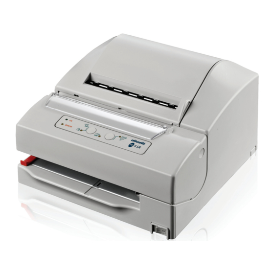
1. OVERVIEW 1.1 INTRODUCTION The PR4 SLIP is an impact printer specifically designed for the POS retail environment. It can print documents, cheques and receipts. The documents to be printed are aligned automatically once inserted into the front slot. Models equipped with the MICR option can read the bar codes on cheques. -
Page 6: Overall View Of The Printer
1.2 OVERALL VIEW OF THE PRINTER WINDOW PAPER CONSOLE FRONT COVER OUTPUT FRONT INSERTION SLOT Fig. 1-1 XYAA6338... -
Page 7: Block Diagram
BLOCK DIAGRAM Printing module MICR reader* Slip Paper Module Mechanical devices * = specific version MICR reader Main board board Console Power Supply Electronics * = specific version Fig.1-2 XYAA6338 Service Manual... -
Page 8: Interconnections
1.4 INTERCONNECTIONS Fig. 1-3 XYAA6338... -
Page 9: Power Supply Characteristics
1.5 POWER SUPPLY CHARACTERISTICS The machine must be equipped with a power supply of the following characteristics: DC VOLTAGE POWER 24 V +20 -10% 45 W (max. 75 W) The following power supplies are optionally available to the user: 1) External AC power supply: VOLTAGE POWER FREQUENCY... -
Page 10: Layout Of The Drawer And Display Connectors
1.6 LAYOUT OF THE DRAWER AND DISPLAY CONNECTORS By means of the drawer and display option it is possible to drive a client drawer and display. • Drawer Connector Solenoid resistance 24 ohm min Output voltage 24 volts Current 1 amp Max Printer side connector Molex 52065-6615 or equivalent 1 Frame GND... -
Page 11: Interfaces
1.7 INTERFACES 1.7.1 RS-232 Serial Interface Connector Layout • RS232 Connector - PIN functions Signal Frame GND — Transmitter data Receiver data Fix to ‘Space” level Space(+12) the host can receive data Mark(-12) the host cannot receive data When DTR/DSR control is selected, the printer transmits data after confirming this signal. -
Page 12: Iee 1284 Parallel Interface Connector Layout
1.7.2 IEE 1284 Parallel Interface Connector Layout Signal Source STROBX Host 2 to 9 DACX (0-7) Host/Printer ACKX0 Printer BUSYX Printer PAPEMX Printer SETOUX Printer AUTLFX Host FAULTX Printer IMPRAX Host SELINX Host 18 to 25 XYAA6338... -
Page 13: Installation
2. INSTALLATION 2.1 UNPACKING THE PRINTER It is suggested that you carefully open the printer packaging and store it in a safe place so that it can be used again if the printer needs to be transported to another site. The printer is protected by a polyethylene covering. -
Page 14: Checking The Packaging Contents
2.2 CHECKING THE PACKAGING CONTENTS In addition to the printer, the packaging always contains a ribbon cartridge Depending on the order made by the client, the following options may be present: A Power cord B External power supply C Front insertion tray Fig. -
Page 15: Removing The Blockages Used For Transportation
2.3 REMOVING THE BLOCKAGES USED FOR TRANSPORTATION • Remove the plastic strip from the front feed slot. • Open the front cover by turning it upwards. • Remove the cardboard that blocks the print head. • Close the printer cover. Fig. -
Page 16: Inserting The External Transformer
2.4 INSERTING THE EXTERNAL TRANSFORMER Proceed as explained below to insert the optional external transformer into the printer: 1. Attach the power cord to the external transformer. 2. Release tabs A and lift off cover B located at the rear of the printer. -
Page 17: Connections
2.5 CONNECTIONS 1. Attach the DC power cord to the related connector underneath the printer. 2. Attach the serial interface cable to the related connector underneath the printer. Fig. 2-5 XYAA6338 Service Manual... -
Page 18: Functional Checks
3. FUNCTIONAL CHECKS 3.1 LEDS There are five LEDs on the console indicating, respectively: LED 1 - ON When on, indicates that the printer is powered. LED 2 - error When on, indicates that the printer crashed. When flashing, indicates a mechanical error. LED 3 When on, indicates that the printer is waiting for a form to be inserted from the top. -
Page 19: Console Indications
3.2 CONSOLE INDICATIONS Different failures (errors or malfunctions) are signaled on the console in the following ways: • Error LED (LED 2) flashing • Error LED (LED 2) flashing + other LEDs on • Error LED (LED 2) on. The following table summarizes all the possible LED indications: Ref. - Page 20 For a detailed description of Ref. 7, press any key and the LEDs will assume one of the following configurations: Ref. Ref. Ref. LED Indications on the Console Ref. Ref. LED Indications on the Console LED Indications on the Console LED Indications on the Console LED Indications on the Console Failure Signaled...
-
Page 21: Slip Test
SLIP TEST Activating this procedure makes it possible to check the efficiency of the slip alignment assembly. Operator action: Activate the slip test mode as described in Secton 4. Printer action: 1. Mechanical reset 2. Waits for slip insertion Operator action: Insert the slips successively and check alignment. -
Page 22: Setup And Adjustments
4. SETUP AND ADJUSTMENTS Proceed as follows to setup and/or adjust the printer: An acoustic signal sounds and the three LEDs located on the lower part of the control console light to indicate a. Open the printer's front cover. when the printer switches to the initial status menu. b. -
Page 23: Operator Test
4.1 OPERATOR TEST If the printer's front cover is closed while the printer is in the Operator Test LED configuration (refer to the table on the previous page) and one of the two console keys is pressed, the printer's firmware release, defined setup parameters and character set configured will be printed on a sheet of paper. -
Page 24: Selectable Parameters
See also the following sections: • Selectable Parameters • Selecting the Parameters 4.2.2 Selectable Parameters The parameters that can be selected via Setup are grouped as indicated in the following diagram, which is similar to the one prined by the machine: EMULATION EMULATION: EPSON TM-U590 I/O: SERIAL - EXIT... -
Page 25: Selecting The Parameters
4.2.3 Selecting the Parameters After accessing Setup as explained in the section Accessing Setup (Section 4.2.1), pressing one of the two buttons on the control console will cause the machine to print the first main menu. By successively pressing the 1 - SKIP key, a new LED lighting sequence is initiated and a new menu is made available. -
Page 26: Set-Up Diagram (Olivetti Serial Port Emulation)
4.2.4 SET-UP Diagram (Olivetti Serial Port Emulation) When switching to the SET-UP mode, the printer can be programmed as indicated in the following diagram: enter Serial enter Bit/char enter 7 bit skip 8 bit skip skip enter enter skip skip... -
Page 27: (Epson Serial Port Emulation)
4.2.5 SET-UP Diagram (EPSON Serial Port Emulation) With the printer in the Setup mode, select the parameters by following the flow charts provided below. enter Bit/char skip 8 bit enter Serial enter 7 bit skip skip skip enter enter skip enter 9600 4800... -
Page 28: Set-Up Diagram (Epson Parallel Port Emulation)
4.2.6 SET-UP Diagram (EPSON Parallel Port Emulation) With the printer in the Setup mode, select the parameters by following the flow charts provided below. Emulation enter CP 437 skip CP 852 CP 858 CP 860 skip Epson 590 enter User enter Nation enter... -
Page 29: Disassembly/Reassembly Procedures
5. DISASSEMBLY/REASSEMBLY PROCEDURES 5.2 REMOVING THE CASE 5.1 OVERVIEW • Open the front and rear covers by rotating them This chapter is divided into two parts which describe completely around their respective hinges . how to disassemble/reassemble the parts and how to make the related adjustments. - Page 30 • To remove the printer case, proceed in the direction shown by the arrows in the figure below. After manually releasing the case from the base of the machine, slide it upwards. Fig. 5-2 XYAA6338...
-
Page 31: Locating The Components On The Electronic Board
5.3 LOCATING THE COMPONENTS ON THE ELECTRONIC BOARD 5.3.1 Main Board XYAA6338 Service Manual... - Page 32 LEGEND: Ref. Description SLIP motor fuse Main fuse Carriage motor fuse Display/drawer board connector Needle head connector Slip motor connector Slip photo connector Paper photo connector Power supply connector MICR board connector Console connector Carriage motor connector RS 232 serial interface connector U1,U2 Needle drivers U5,U6...
-
Page 33: Micr Board
5.3.2 MICR Board XYAA6338 Service Manual... - Page 34 LEGEND: Ref. Description To main board N.U. Head connector Microprocessor US10 EEPROM XYAA6338...
-
Page 35: Removing The Print Assembly
5.4 REMOVING THE PRINT ASSEMBLY • Remove the case (Section 5.2). • Disconnect all the connectors from the electronic board and separate the machine from the base. • Loosen screws 1 and 2 and then lift the machine off its base (Fig. 5-3). •... -
Page 36: Removing The Print Head
5.5 REMOVING THE PRINT HEAD • Remove the case (Section 5-2). • To completely extract the print head and related flat cable remove the board shown in Figure 5-14; • Remove screw 1. gently bend this board so that it can be removed. •... -
Page 37: Removing The Platen
5.8 REMOVING THE PLATEN • To reassemble the platen follow its disassembly • Remove the case (Section 5.2). procedure in reverse order and align as shown in • Remove the print assembly (Section 5.4). the figure. • Extract the plate by sliding it from the front (head side). -
Page 38: Removing The Carriage Motor
5.7 REMOVING THE CARRIAGE MOTOR • After having removed the plastic board, remove screws A and B so that you can then remove • Remove the case (Section 5.2). the motor. • Proceed as explained in Section 5.4 to access the print assembly. -
Page 39: Removing The Ribbon Movement Pin
5.8 REMOVING THE RIBBON MOVEMENT PIN • Remove the printer front cover. Remove the exchanger using a pair of pliers (Fig. 5-9). The pin is now free and can be removed • Remove the flat cable guide board upwards by pulling it upwards. (Fig. -
Page 40: Removing The Document
5.9 REMOVING THE DOCUMENT DETECTION PHOTOSENSORS • Remove the case (Section 5.2). • Remove screws 1 and 2 (Sections 5-4) and then disconnect all the connectors from the electronic board so that the machine can be separated from the base. •... -
Page 41: Removing The Slip Detection
5.10 REMOVING THE SLIP DETECTION PHOTOSENSORS • Remove the assembly by unscrewing the securing screw shown in the figure. • Remove the case (Section 5.2). • Remove the print assembly (Section 5.4). • Remove the paper guide plate in order to be able to Note: The photosensor assembly must be adjusted access the photosensor assembly. -
Page 42: Removing The Line Feed Motor
5.11 REMOVING THE LINE FEED MOTOR 5.11.1 Basic Printer Version • Remove the line feed motor securing screws 1 and • Remove the case (Section 5.2). 2 (Fig. 5-13). • Remove gears A and B after removing circlips C. • Remove motor D. Fig. -
Page 43: Removing The Boards
5.12 REMOVING THE BOARDS 5.12.2 Drawer and Display Card 5.12.1 Main Board • Remove the case (Section 5.2). • Remove the case (Section 5.2). • Lift the printer's mechanical assy. • Lift the printer's mechanical assy. • Disconnect the connector. •... -
Page 44: Adjustments
6. ADJUSTMENTS The following sections describe the adjustments to be made on the different printer assemblies. 6.1 ADJUSTING THE PLATEN ON THE BASIC STRUCTURE After replacing the platen check the parallelism between the platen and the basic structure. Parallelism with the carriage guide plate is obtained using a caliber and by adjusting the three securing screws (tolerance of + 0.1mm). -
Page 45: Adjusting The Parallelism And Print Head-Platen Distance
6.2 ADJUSTING THE PARALLELISM 6.4 MOUNTING THE SNAP RINGS ON AND PRINT HEAD-PLATEN THE CARRIAGE TRANSPORT DISTANCE ASSEMBLY During the assembly of codes 474067T, 474059B and By means of friction screws 923010Q, higher or lower 474026J, snap ring code 474241E must have a the plate code 474031P until obtaining the parallelism clearance of 0.1 - 0.2 (Fig. -
Page 46: Adjusting The Clearance Of The Document Insertion Slot
6.5 ADJUSTING THE CLEARANCE OF THE DOCUMENT INSERTION SLOT Fig. 6-5 Using a specific probe, make sure that there is a clearance of 2.5 mm between the frame shield code 474030S and the frame in zama code 474017R. XYAA6338 Service Manual... -
Page 47: Adjusting The Paper Detection Photosensor
6.6 ADJUSTING THE PAPER DETECTION PHOTOSENSOR Fig. 6-6 Once bar parallelism is performed, place an 0.5 mm thick plate between the rollers code 474041Z and code 474037M. Move the photo assembly code 475478D in contact with the plate and then tighten screw code 924966Q. -
Page 48: Adjustment Menu
6.7 ADJUSTMENT MENU To enter into the Adjustment Menu follow the instructions explained in Section 4. After the mechanical reset performed once the menu is entered, the console will assume the following configuration: LED 2 ON LED 3 OFF LED 4 OFF LED 1 Key1 Key 2... -
Page 49: Photosensor Adjustments
6.7.1 Photosensor Adjustments After a reset the carriage moves to the far left position where the first phase of the adjustment procedure is carried out and which consists of multiple reads of the photosensors in out of paper conditions. The console assumes the following configuration during this phase: Flashing LED 3 LED 1... - Page 50 Console Configuration: Flashing LED 4: LED 1 Key 1 Key 2 LED 5 LED 2 LED 3 LED 4 Fig. 6-10 Operator Action Press key 2 (OK): LED 1 Key 1 Key 2 Key 5 LED 4 LED 2 LED 3 Fig.
-
Page 51: Adjusting The Carriage
Photosensor Adjustment Errors Any error detected is signalled by the flashing of the console LEDs in the following way: LED 2 LED 3 LED 4 LED 5 Photosensor Error Blink Upper Blink Lower Blink Slip 1 Blink Slip 2 In case of error press Key 2 (OK) to return to the initial configuration. - Page 52 Printer Action Performs a mechanical reset with the values calculated during the procedure. Any error detected by the printer will be signalled as follows: LED 2 LED 2 LED 4 LED 5 Error Blink Carriage reset error Otherwise: Printer Action Stores the value in EEPROM.
-
Page 53: Micr Adjustment
6.7.3 MICR Adjustment This adjustment must be made using the MICR calibration card code 474245 A (special check) on which the reference value is printed on the center bottom part of the card. Before beginning, make sure that the paper rolls are installed since the printer will have to print the values referring to the calibration card. - Page 54 Second part of the calibration procedure : Console configuration: Flashing LED 5 Key 2 LED 1 Key 1 LED 5 LED 4 LED 2 LED 3 Fig. 6-14 Operator action: Insert the check Printer action: Inserts the check Console configuration: Flashing LED 3: LED 1 Key 2...
- Page 55 Printer action: Performs a read cycle. Calibration is performed by carrying out the second part of the calibration procedure FIVE TIMES. The operator must therefore insert the check five times. Upon completion the outcome of the calibration procedure will be printed: Calibration OK A/D saturation Too many peaks...
-
Page 56: Installing The Drawer Card Option
7. INSTALLING THE DRAWER CARD OPTION • Open the machine by following the procedure described in Section 5.2. • Insert the card A into the appropriate slots B on the printer base (see Figure 7-1) and then attach one end of the connection cable to connector C on the card and the other end to connector J9 on the main board.