Table of Contents
Advertisement
Quick Links
Advertisement
Table of Contents

Related Manuals for Interlogix FS MC250-1T/1S


Summary of Contents for Interlogix FS MC250-1T/1S
- Page 1 IFS MC250-1T/1S User Manual P/N 1072573 • REV R00.03 • ISS 10SEP12...
- Page 2 Copyright © 2012 UTC Fire & Security Company. All rights reserved. Trademarks and Interlogix, IFS MC250-1T/1S, the IFS Brand and patents logo are trademarks of UTC Fire & Security. Other trade names used in this document may be trademarks or registered trademarks of the manufacturers or vendors of the respective products.
- Page 3 European Union. For proper recycling, return this product to your local supplier upon the purchase of equivalent new equipment, or dispose of it at designated collection points. For more information see: www.recyclethis.info. Contact www.utcfireandsecurity.com information www.interlogix.com Customer support www.interlogix.com/customer-support...
-
Page 5: Table Of Contents
Contents Overview 1 Package Contents 1 Product Features 2 Installation 3 Product Description 3 Front Panel 5 LED Indicators 6 Converter Top Panel 7 Wiring the Power Inputs 7 Wiring the Fault Alarm Contact 8 Mounting Installation 9 Installation Steps 13 Switch Operation 14 Troubleshooting 16 Specifications 17... -
Page 7: Overview
Overview This section describes the functionalities of the IFS MC250- 1T/1S Industrial Media Converter’s components and guides how to install it on the desktop. Basic knowledge of networking is assumed. Please read this chapter completely before continuing. In the following section, the term “Industrial Media Converter”... -
Page 8: Product Features
Product Features Physical Port MC250-1T/1S 1-Port 10/100Base-TX RJ-45 1-Port 100Base-FX SFP slot (Distance depends on SFP module) Industrial Design Slim type IP-30 metal case -40 to +75 Degree C operating temperature DIN rail and wall mount design 12 to 48V DC, redundant power with polarity reverse protection and detachable terminal block connectors for master and slave power Supports EFT protection 6000V DC for power line... -
Page 9: Installation
Installation This section describes the functionalities of the Industrial Fast Ethernet Switch’s components and guides how to install it on the desktop. Basic knowledge of networking is assumed. Please read this chapter completely before continuing. In the following section, the term “Industrial Fast Ethernet Switch”... - Page 10 With the Fast Ethernet SFP interface, the MC250-1T/1S extends the transmission distances from 220km to 70Km. The actual distance is defined by the Fast Ethernet SFP module selected. The IFS family of Fast Ethernet SFP modules comes with one of the following models. The following list shows the available Modules for MC250-1T/1S.
-
Page 11: Front Panel
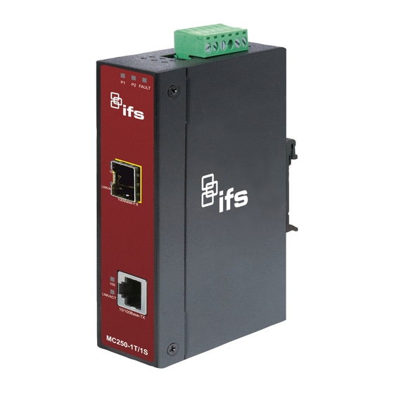
Front Panel The figure below shows the Front Panel of the MC250-1T/1S. IFS MC250-1T/1S User Manual... -
Page 12: Led Indicators
LED Indicators System Color Function Green Indicates that power 1 is on. Green Indicates that power 2 is on. Fault Green Indicates either power 1 or power 2 has no power. Per 10/100Base-TX Port Color Function Indicates that the link through that port is Light successfully established at 100Mbps. -
Page 13: Converter Top Panel
Converter Top Panel The top panel of the MC250-1T/1S consists of a terminal block connector with two DC power inputs. Wiring the Power Inputs The 6-contact terminal block connector on the top panel of the MC250-1T/1S is used for two DC redundant powers inputs. Please follow the steps below to insert the power wires. -
Page 14: Wiring The Fault Alarm Contact
Power 1 Fault Power 2 Wiring the Fault Alarm Contact The fault alarm contacts are in the middle of the terminal block connector as the picture shows below. Inserting the wires, the MC250-1T/1S will detect the fault status of the power failure and then forms an open circuit. -
Page 15: Mounting Installation
Mounting Installation This section describes how to mount the MC250-1T/1S and make connections to it. Please read the following section and perform the procedures in the order presented. Note: In the installation steps below, this Manual uses the IFS 8 Port Industrial Gigabit Switch, GE-DSGH-8, as an example. However, the steps for any IFS Industrial Switch &... - Page 16 1. Lightly press down and push the bottom of the DIN-Rail connector mount into the track. 2. Check that the DIN-Rail connector mount is tightly mounted on the track. 3. Please refer to following procedures to remove the MC250- 1T/1S from the track. IFS MC250-1T/1S User Manual...
- Page 17 4. Lightly press down and pull the bottom of DIN-Rail connector mount to remove it from the track. Mounting to a Wall To install the MC250-1T/1S on the wall, please follow the instructions described below. 1. Loosen the screws to remove the DIN Rail from the Media Converter.
- Page 18 2. Place the wall mount plate on the rear panel of the MC250- 1T/1S. 3. Assemble the wall mount plate on the MC250-1T/1S 4. Use the hook holes at the corners of the wall mount plate to hang the MC250-1T/1S on the wall. IFS MC250-1T/1S User Manual...
-
Page 19: Installation Steps
Installation Steps Step 1: Unpack the Industrial Fast Ethernet Switch. Step 2: Check that DIN-Rail is screwed on the Industrial Fast Ethernet Switch. (Please refer to the DIN-Rail Mounting section for DIN-Rail installation. If you want to wall mount the Industrial Fast Ethernet Switch, then please refer to Wall Mount Plate Mounting section for wall mount plate installation. -
Page 20: Switch Operation
Switch Operation Address Table The Industrial Fast Ethernet Switch is implemented with an address table. This address table is composed of many entries. Each entry is used to store the address information of each node in the network, including MAC address, Port No., etc. - Page 21 from the frames before transmission. Lack of error packet occurrence is important for an efficient and stable network.. The Industrial Fast Ethernet Switch scans the destination address from the packet-header, searches the routing table provided for the incoming port and forwards the packet, only if required.
-
Page 22: Troubleshooting
Troubleshooting This chapter contains information to help resolving issues. If the Industrial Fast Ethernet Switch is not functioning properly, make sure the device was set up according to instructions in this manual. The Link LED is not light Solution: Check the cable connection of the Industrial Fast Ethernet Switch. -
Page 23: Specifications
Specifications Product MC250-1T/1S Hardware Specification 10/100Base-TX Port 1 RJ-45 Auto-MDI/MDI-X port 100Base-FX Port 1 SFP Slot Fiber Port Type Cable Distance Optical Frequency Deprends by SFP module Launch Power (dBm) Receive Sensitivity (dBm) Maximum Input Power (dBm) Dimension (W x D x H) 135mm x 85mm x 32mm 430g Weight... -
Page 24: Rj45 Pin Assignments
When connecting to other Ethernet equipment such as a Router, Bridge, Switch, or Hub, please refer to that device’s Technical Manual. RJ45 Pin Assignments 10/100Mbps, 10/100Base-TX RJ-45 Connector pin assignment MDI-X Contact Media Dependant Media Dependant Interface Interface -Cross Tx + (transmit) Rx + (receive) Tx - (transmit) Rx - (receive) - Page 25 Please make sure your connected cables are with same pin assignment and color as above picture before deploying the cables into your network. IFS MC250-1T/1S User Manual...
-
Page 26: Contacting Technical Support
Contact technical support if you encounter any difficulties during this installation. Please make sure you have the requested diagnostic or log files ready before you contact us by phone or go to www.interlogix.com/customer-support. Technical Support Europe, Middle East and Africa Select Contact Us at www.utcfssecurityproducts.eu...