Table of Contents
Advertisement
Quick Links
Advertisement
Table of Contents

Related Manuals for Interlogix IFS MC350-1T-2S


Summary of Contents for Interlogix IFS MC350-1T-2S
- Page 1 IFS MC350-1T-2S User Manual P/N 1072683 • REV A • ISS 22OCT13...
- Page 2 © 2013 United Technologies Corporation Copyright Interlogix is part of UTC Climate Controls & Security, a unit of United Technologies Corporation. All rights reserved. The IFS MC350-1T-2S name and logo are trademarks of United Trademarks and patents Technologies. Other trade names used in this document may be trademarks or registered trademarks of the manufacturers or vendors of the respective products.
-
Page 3: Table Of Contents
TABLE OF CONTENTS 1 . INTRODUCTION……………………………………………………………………………………4 1 .1 P ......................4 ACKAGE ONTENTS 1 .2 H .....................4 OW TO ANUAL 1 .3 P ......................5 RODUCT EATURES 1 .4 P .....................6 RODUCT PECIFICATIONS 1 .5 P ......................8 HYSICAL IMENSIONS 2 . INSTALLATION……………………………………………………………………………………9 2 .1 P ......................9 RODUCT... -
Page 4: Introduction
1. INTRODUCTION 1.1 Package Contents Check the contents of your package for the following parts: Industrial Gigabit Media Converter x 1 ● User's Manual x 1 ● If any of these are missing or damaged, please contact your dealer immediately; if possible, retain the carton including the original packing material, and use them against to repack the product in case there is a need to return it to us for repair. -
Page 5: Product Features
1.3 Product Features Physical Port 1-port 10/100/1000Base-T RJ-45 with auto MDI / MDI-X function 2 SFP interfaces, 100/1000Base-X dual mode (DIP switch control) Layer 2 Features IEEE 802.3 / 802.3u / 802.3ab / 802.3z Ethernet Standard Compliant Supports Auto-negotiation and 10/100Mbps half / full duplex and 1000Mbps full duplex mode Prevents packet loss with back pressure (Half-Duplex) and IEEE 802.3x PAUSE frame flow control (Full-Duplex) 9K Jumbo Frame Size support... -
Page 6: Product Specifications
1.4 Product Specifications Model MC350-1T-2S Hardware Specification 10/100/1000Base-T Ports 2 1000Base-SX/LX/BX SFP interfaces (Port-1 and Port-2) SFP Interfaces Compatible with 100Base-FX SFP 135 x 87 x 32mm Dimensions (W x D x H) 505g Weight DC 12~48V, Redundant power with polarity reverse protection Power Requirements function. - Page 7 IEEE 802.3z Gigabit Ethernet IEEE 802.3x Full-Duplex Flow Control FCC Part 15 Class A, CE Regulation Compliance IEC60068-2-32 (Free fall) IEC60068-2-27 (Shock) Stability Testing IEC60068-2-6 (Vibration) Environment Operating: -40~75 degrees C Temperature Storage: -40~75 degrees C Operating: 5~95% (Non-condensing) Humidity Storage: 5~95% (Non-condensing)
-
Page 8: Physical Dimensions
1.5 Physical Dimensions MC350-1T-2S Industrial Gigabit Media Converter dimensions (W x D x H): 135 x 87 x 32mm... -
Page 9: Installation
2. Installation This section describes the functionalities of the Industrial Gigabit Media Converter’s components and guides how to install it on the desktop. Basic knowledge of networking is assumed. Please read this chapter completely before continuing. 2.1 Product Description Flexibility and Network Distance Extension Solution The MC350-1T-2S Industrial Gigabit Media Converter is equipped with one 10/100/1000Base-T auto-negotiation port and two 100/1000X SFP slots. -
Page 10: Converter Front Panel
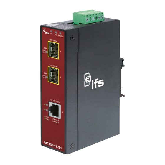
2.1.1 Converter Front Panel Figure 2-1 shows the front panel of Industrial Gigabit Media Converter. Figure 2-1: MC350-1T-2S Front Panel... -
Page 11: Led Indicators
2.1.2 LED Indicators System Color Function Lit: indicate power 1 has power. Green Lit: indicate power 2 has power. Green Lit: indicate either power 1 or power 2 has no power. FAULT Green Per 10/100/1000T Port Color Function Lit: indicate the link through that port is successfully established at 100Mbps or Orange 10Mbps. -
Page 12: Converter Upper Panel
2.1.3 Converter Upper Panel The upper panel of the Industrial Gigabit Media Converter consists of one terminal block connector within two DC power inputs, and also provides 3 DIP Switches for 100/1000X fiber support on two SFP slots and fiber redundant function. Figure shows the upper panel of the Industrial Gigabit Media Converter. -
Page 13: Wiring The Power Inputs
2.1.4 Wiring the Power Inputs The 6-contact terminal block connector on the top panel of Industrial Gigabit Media Converter is used for two DC redundant power inputs. Please follow the steps below to insert the power wire. Insert positive / negative DC power wires into contacts 1 and 2 for POWER 1, or 5 and 6 for POWER 2. V1- V1 + V2 - V2 + Tighten the wire-clamp screws for preventing the wires from loosening. -
Page 14: Wiring The Fault Alarm Contact
2.1.5 Wiring the Fault Alarm Contact The fault alarm contacts are in the middle of the terminal block connector as the picture shows below. Inserting the wires, the Industrial Gigabit Media Converter will detect the fault status of the power failure and then forms an open circuit. The following illustration shows an application example for wiring the fault alarm contacts. -
Page 15: Cabling
2.1.6 Cabling 10/100/1000Base-T and 100Base-FX / 1000Base-SX/LX The 10/100/1000Base-T port comes with Auto-Negotiation capability. It automatically supports 1000Base-T, 100Base-TX and 10Base-T networks. Users only need to plug a working network device into the 10/100/1000Base-T port, and then turn on the Industrial Gigabit Media Converter. The port will automatically runs in 10Mbps, 20Mbps, 100Mbps or 200Mbps and 1000Mbps or 2000Mbps after the negotiation with the connected device. - Page 16 2.1.6.1 Installing the SFP Transceiver The sections describe how to insert an SFP transceiver into an SFP slot. The SFP transceivers are hot-pluggable and hot-swappable. You can plug in and out the transceiver to/from any SFP port without having to power down the Industrial Gigabit Media Converter as Figure 2-3 shows..
- Page 17 Fast Ethernet SFP Transceiver Modules IFS Model SFP Description S35-2MLC SFP, LC Connector, Multi Mode, Gigabit, 2 fiber,850nm/850nm, 550m, Hardened -40~75°C S35-2SLC-10 SFP, LC Connector, Single Mode, Gigabit, 2 fiber,1310nm/1310nm, 10km, Hardened -40~75°C S35-2SLC-30 SFP, LC Connector, Single Mode, Gigabit, 2 fiber,1310nm/1310nm, 30km, Hardened -40~75°C S35-2SLC-70 SFP, LC Connector, Single Mode, Gigabit, 2 fiber,1550nm/1550nm, 70km, Hardened -40~75°C S20-1SLC/A-20...
- Page 18 1000Base-SX/LX: Before connecting the other switches, workstation or Media Converter, please do the following: Set the DIP Switch of SFP Port 1 or Port 2 to the “OFF” position with fiber speed 1000Base-X. Port 1 (DIP 1) 100FX 1000X Port 2 (DIP 2) 100FX 1000X Make sure both sides of the SFP transceiver are with the same media type;...
- Page 19 Connect the fiber cable Attach the duplex LC connector on the network cable to the SFP transceiver. Connect the other end of the cable to a device, switches with SFP installed, to fiber NIC on a workstation or a Media Converter.
-
Page 20: Redundancy Overview
2.1.7 Redundancy Overview The Industrial Gigabit Media Converter provides rapid fiber redundancy of link for highly critical Ethernet applications. The redundant-mode supports auto-recover function. If the destination port of a packet is link down, it forwards the packet to the other port of the backup pair. The following figure shows the redundant function. Figure 2-5: Redundancy Behavior Topology Link status auto detect and redundant on Dual ports with same connector type. -
Page 21: Mounting Installation
2.2 Mounting Installation This section describes how to install the Industrial Gigabit Media Converter and makes connections to it. Please read the following topics and perform the procedures in the order being presented. In the installation steps below, this Manual uses IGS-801(IFS 8 Port Industrial Gigabit Switch) as the example. - Page 22 Step 3: Make sure the DIN-Rail is tightly secured on the track. Step 4: Please refer to the following procedures to remove the Industrial Gigabit Media Converter from the track. Step 5: Lightly pull out the bottom of the DIN-Rail from the track to remove.
-
Page 23: Wall Mount Plate Mounting
2.2.2 Wall Mount Plate Mounting To install the Industrial Gigabit Media Converter on the wall, please follow the instructions described below. Step 1: Remove the DIN-Rail from the Industrial Gigabit Media Converter; loose the screws to remove the DIN-Rail. Step 2: Place the wall mount plate on the rear panel of the Industrial Gigabit Media Converter. Step 3: Use the screws to screw the wall mount plate on the Industrial Gigabit Media Converter. -
Page 24: Application
3. Applications In this paragraph, we will describe how to install the Industrial Gigabit Media Converter. Transportation Networking Industrial Operating Environment... - Page 25 Installation Steps 1: Unpack the Industrial Gigabit Media Converter. Step Step 2: Check whether the DIN-Rail is screwed on the Industrial Gigabit Media Converter. (Please refer to DIN-Rail Mounting section for DIN-Rail installation if the DIN-Rail is not screwed on the Industrial Gigabit Media Converter). If you want to wall-mount the Industrial Gigabit Media Converter, then please refer to the Wall Mount Plate Mounting section for wall mount plate installation.
-
Page 26: Troubleshooting
4. Troubleshooting This chapter contains information to help you solve issues. If the Industrial Gigabit Media Converter is not functioning properly, make sure the Industrial Gigabit Media Converter is set up according to instructions in this manual. The per port LED is not lit Solution: Check the cable connection of the Industrial Gigabit Media Converter. -
Page 27: Cable Connection Parameters
5. Cable Connection Parameters The wiring details are as below: 100FX Fiber Optical Cables: ■ Standard Fiber Type Cable Specification 100Base-FX Multi-mode 50/125μm or 62.5/125μm (1300nm) 100Base-FX Multi-mode 50/125μm or 62.5/125μm (1310nm) Single-mode 9/125μm 100Base-BX-U Single-mode 9/125μm (TX :1310/RX :1550) 100Base-BX-D (TX :1550/RX :1310) 1000X Fiber Optical Cables:... -
Page 28: Appendix A: Networking Connection
APPENDIX A: Networking Connection A.1 Converter’s RJ-45 Pin Assignments 1000Mbps, 1000Base-T Contact MDI-X BI_DA+ BI_DB+ BI_DA- BI_DB- BI_DB+ BI_DA+ BI_DC+ BI_DD+ BI_DC- BI_DD- BI_DB- BI_DA- BI_DD+ BI_DC+ BI_DD- BI_DC- 10/100Mbps, 10/100Base-TX RJ-45 Connector pin assignment MDI-X Contact Media Dependant Media Dependant Interface Interface -Cross Tx + (transmit) - Page 29 A.2 RJ-45 Cable Pin Assignments The standard RJ-45 receptacle/connector There are 8 wires on a standard UTP/STP cable and each wire is color-coded. The following shows the pin allocation and color of straight cable and crossover cable connection: Straight Cable SIDE 1 SIDE2 SIDE 1...